RetroRiter
A Pi Zero based desktop computer with attached thermal printer.
A Pi Zero based desktop computer with attached thermal printer.
To make the experience fit your profile, pick a username and tell us what interests you.
We found and based on your interests.
Getting back to work after a bit of a hiatus.
I want to get things turning on. Which means power. Which means connections. And the "power distribution box." I've decided to forge on without bothering with a PCB for the switches / connectors on in the power distribution box. Instead I'm just going to hardwire the bits as I add them on.
I decided to mount a proto-board next to the Pi Zero, under the LCD. This gives me a convenient location to add JST connectors so that I can make the Pi / LCD part a bit more modular. It also gives me a spot to add on circuitry, such as a fuse / regulator to protect the Pi. I'm going to power the Pi from the GPIO header, which bypasses some of the protections (see http://raspberrypi.stackexchange.com/a/1618).
Next up will be wiring the first switch, connecting power to the Pi, and testing it all out. For testing, I'm download Raspbian (which is killing my internet connection at the moment). Important note when using the 800x600 HDMI display I have: you may need to force the resolution in /boot/config.txt (see https://learn.adafruit.com/adafruit-5-800x480-tft-hdmi-monitor-touchscreen-backpack/raspberry-pi-config).
I'm typing this on a brand new Leopold FC660M (https://mechanicalkeyboards.com/shop/index.php?l=product_detail&p=1496) which, to be frank, is a rather pretentious keyboard. I mean, totally into the whole mechanical keyboards are a superior typing experience and all of that, but it's also a $110 keyboard in a world of 20 buck keyboards. I want to use this mini computer once it's done, and I have a hipster vision of toting it down to the local coffee shop and setting up in a corner with my homemade computer and type some great manifesto on irony and crappy garage bands. It's expensive. It's less noisy than I expected (Brown Cherry switches). It's a statement.
It's not a cheap keyboard. The original one I had picked up for this project (before it was even really a project) was a mini keyboard that cost 30 bucks (https://www.adafruit.com/products/857). It was cheap, and did the job while testing out a few Raspberry Pi and BeagleBone boards. But the keys were painfully small.
With this new keyboard and the last update talking about deciding to get a PCB made, I realized that money really isn't an issue for me on this project. Which is a departure for me, a normally pretty frugal person. But for this project I'm definitely placing build quality and learning first.
But if you are a frugal person (through choice or consequence): no worries. Buy the cheap keyboard. And skip the custom laser printing. And the PCB board. And the whole useless extra computer to begin with.
I'm not actually going to take this thing to coffee shops.
Oof, sorry for the title.
I've been at a bit of a standstill lately, mostly because both school and work have been busy lately. But also in part because I was just spinning my wheels with KiCad. I am only trying to make a relatively simple board for the power distribution "box" (3 connectors, 1 barrel jack, and 3 switches), but I've never attempted a PCB before. I was considering just wiring it all up with a bunch of shrink wrap to try to keep things neat.
The cons to using a PCB for this project:
The pros:
So after some waffling, I decided to suck it up and try KiCad again. I've started the basic schematic, and I anticipate a lot of issues when it comes to sizing components correctly. I also had to download a library from http://www.kicadlib.org/ to get a DPDT switch component (previously a quiting point for me, but adding libraries is actually easy).
I also figured out the cables I would need, and hand crimped some connectors. This was an exercise in frustration... does anyone know of a cheap family of connectors, pins, and crimps that would work for hobby projects? I've made a few cables at work, and using the correct tools makes it a zen-like experience. But I can't drop $1k on a specialized crimp tool. And using a set of needle nose pliers just doesn't cut it.
Anyways, expect slightly more regular updates and some schematics soon.
I'm starting to think I made a mistake picking an aluminum enclosure for the power distribution box.
I was purchasing other parts on Amazon and my order total came to just shy of the free shipping mark. So I figured, "hey, I'll just add a cheap box / enclosure to stuff the pcb, connectors, and switches for the power distribution box!" So I added an aluminum box for free-ish.
The shipment arrives, and I realize that I don't have any metal working tools. Or experience. So I get a great idea: I'll just swap out the top with a piece of wood and drill whatever I need there. I don't have the time or patience to get all fancy with the Ponoko order, so I just throw 3 rectangles onto my design and figure I'll have three shots to get it right. So here we are.
I should mention that I don't have all that much experience working with wood either.
Anyways, I mark some holes using the aluminum lid as a guide, drill them out, and get passable results. There isn't really enough material on the edges to give me confidence that the lid will last, but it will do. I mark out a few spots for the switches and an opening to pass wires. All in all, it looks okay:
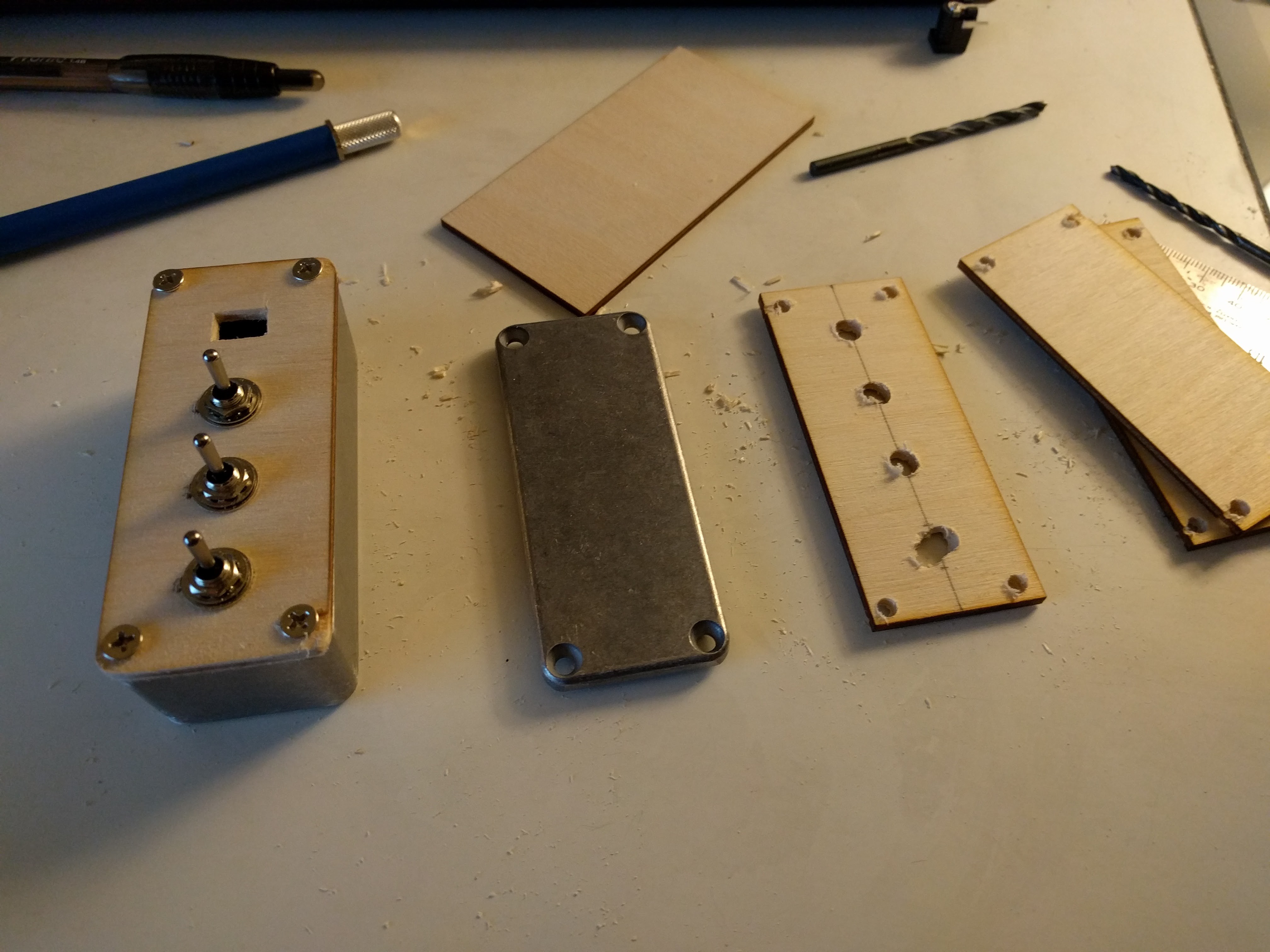
It's going to be a pain to wire, and I don't really have any place to put the connectors I need. I have no idea how the PCB will fit in. I could get away without a PCB, but half of the point of this project was for me to learn how to design / layout a simple one. In retrospect, I could have spent a bit more time laying out the Ponoko order to make a wood box, or at least a sandwich setup similar to what I'm doing for the LCD display. I could have even laser etched some labels. Version 2.0 I guess.
At least I have some switches to throw. Next up will be wiring them up so that they actually do something.
In my last update I talked briefly about what went right with the base. Now on to what went wrong. I made two major errors and a handful of small ones:
Here's what the case looks like with the parts set in place (but no cables):
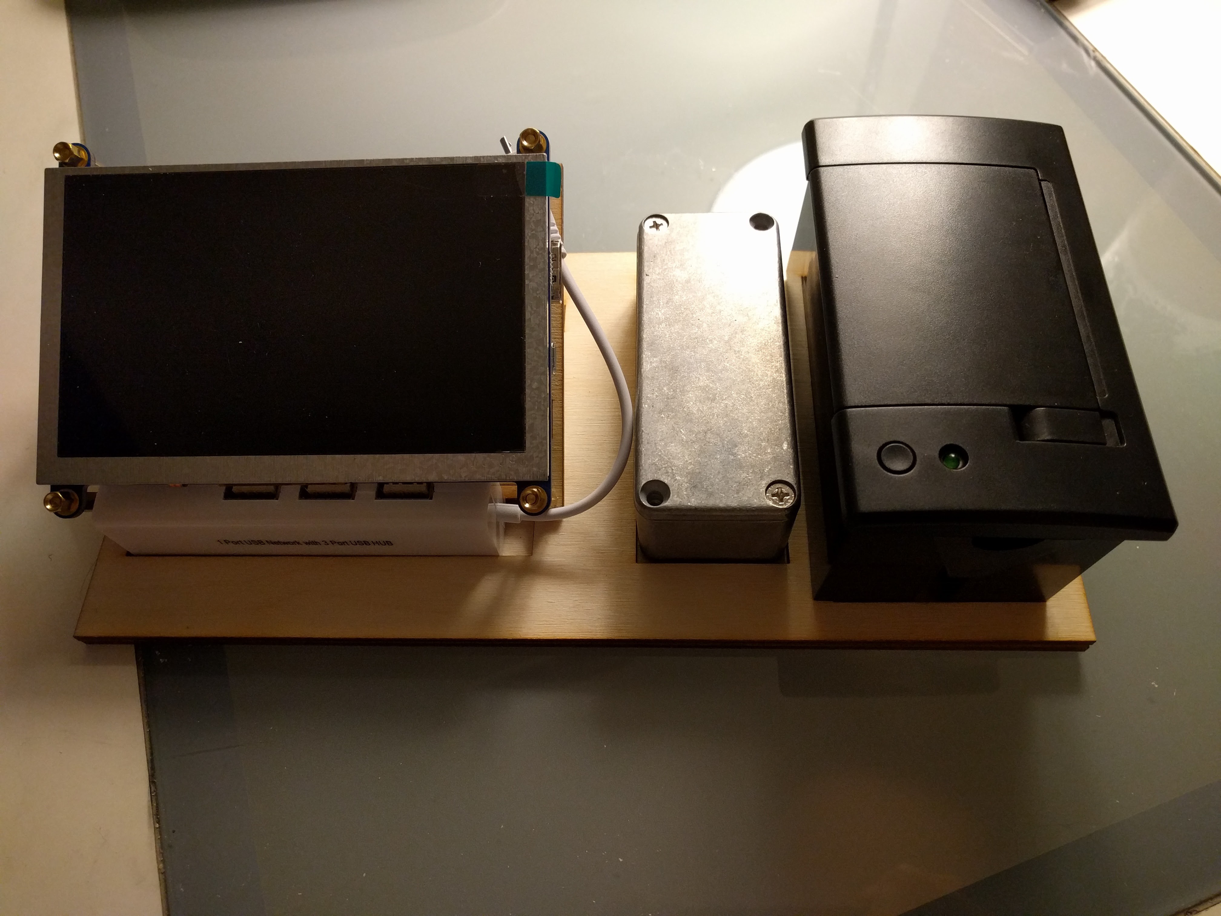
You can just see the left edge of the thermal printer overlapping the second base piece. In the next photo you can see the other major error: the LCD holder knocking into the base.
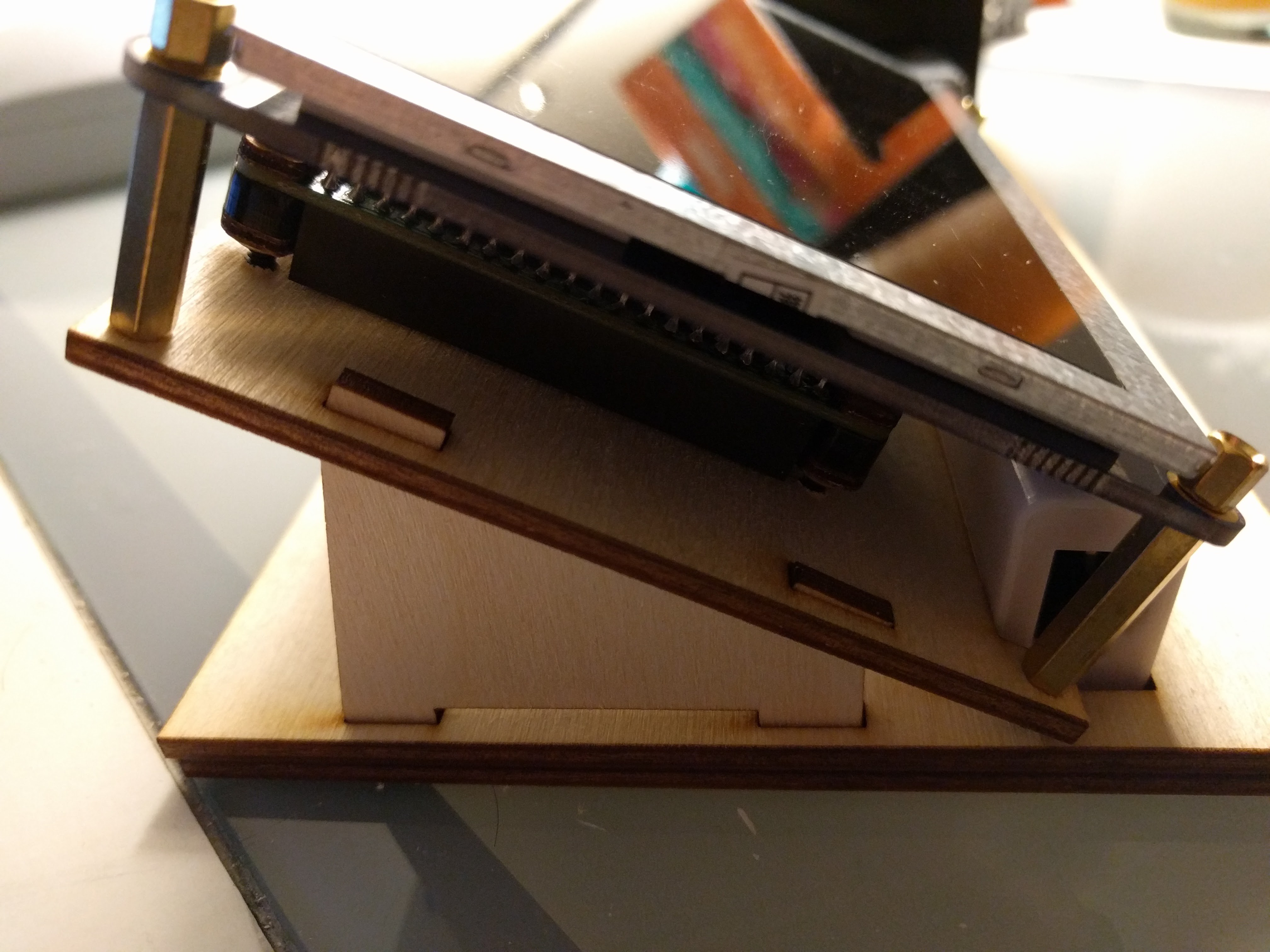 You can also see the Pi Zero in its place.
I still need to work on the base a bit. Mostly I'll be figuring out how to glue the base together, making everything fit well, and then any needed touch-ups. Overall I'm happy with it. Ponoko is a bit pricey for low volumes, and I would have likely been better of taking the dive of learning a real CAD program instead of using Inkscape.
[EDIT:] The .svg file has now been updated to correct the mistakes mentioned here.
I returned home one day to see a package from Ponoko at my door. Hastily I opened, and had a brief panic inducing moment:
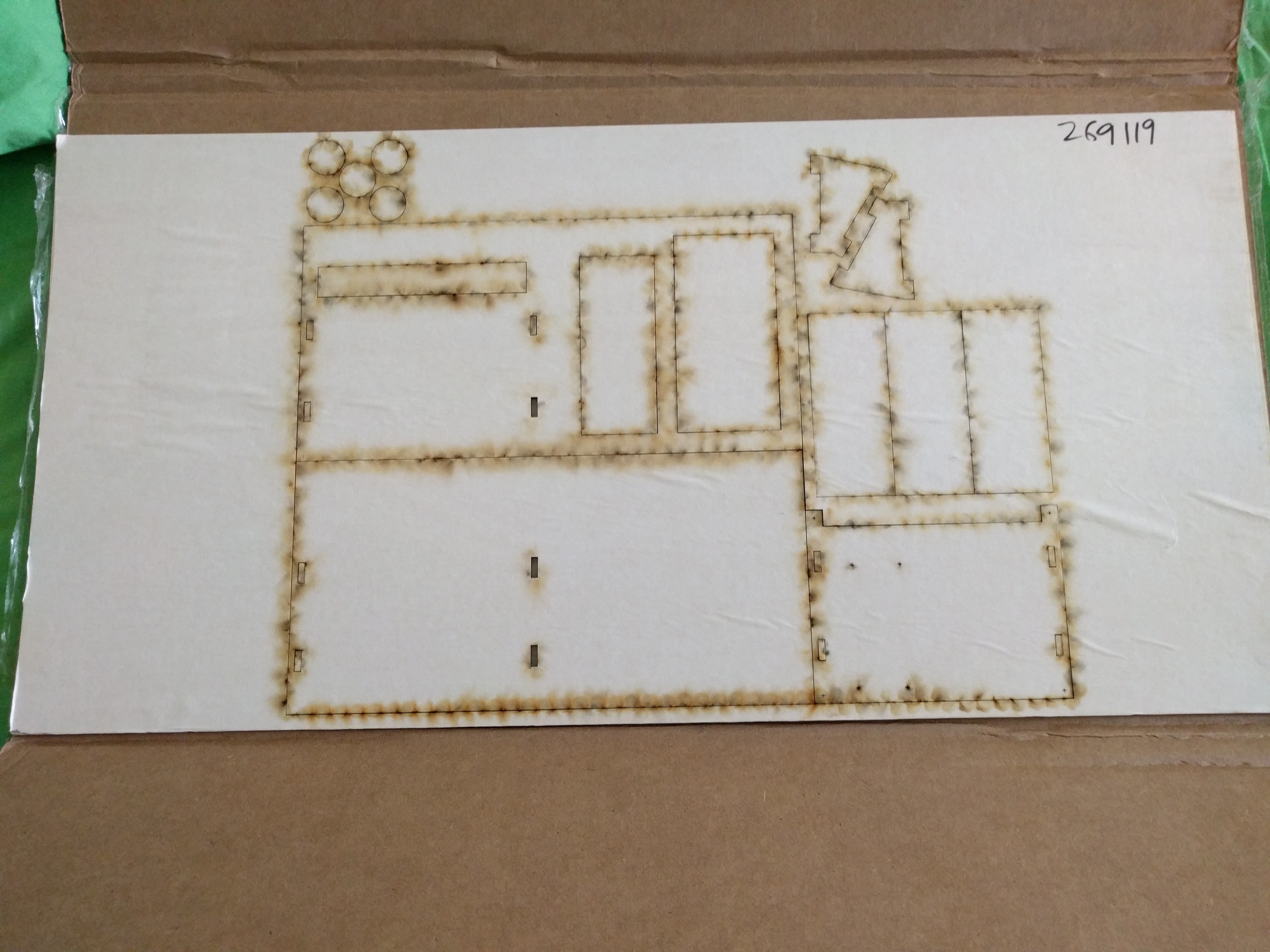 Burn marks everywhere!
But once I peeled off the paper, everything looked fine. Really good in fact. I was worried that a few lines were too close (which can cause burning to the actual wood and not just the paper) but everything turned out great. The only problem with the laser cut was one engraved part wasn't quite dark enough for my tastes, losing some details. But that was on a few extra non-project related parts (spare tokens for a game... the five circles you can see above).
I popped everything off, peeled off the paper, and put everything together. I had two big concerns, but to my surprise, I had only made two(-ish) mistakes in my layout which were unrelated. Well, aside from not filling the entire cut area.
One worry was how I did the screw holes: I made tiny '+' marks to guide a drill instead of cutting a circular hole. This was done to save cutting time and thus money, but in the future I should actually see how much that would save. Unfortunately I only had drill bits and no drill (the bit and brace I have can't hold small diameter bits), so I had to turn the bits by hand. I have a few blisters now, but the wood was soft enough that this amazingly worked. A drill is on my wishlist. Anyways, here what the screw guides look like before and after "drilling":
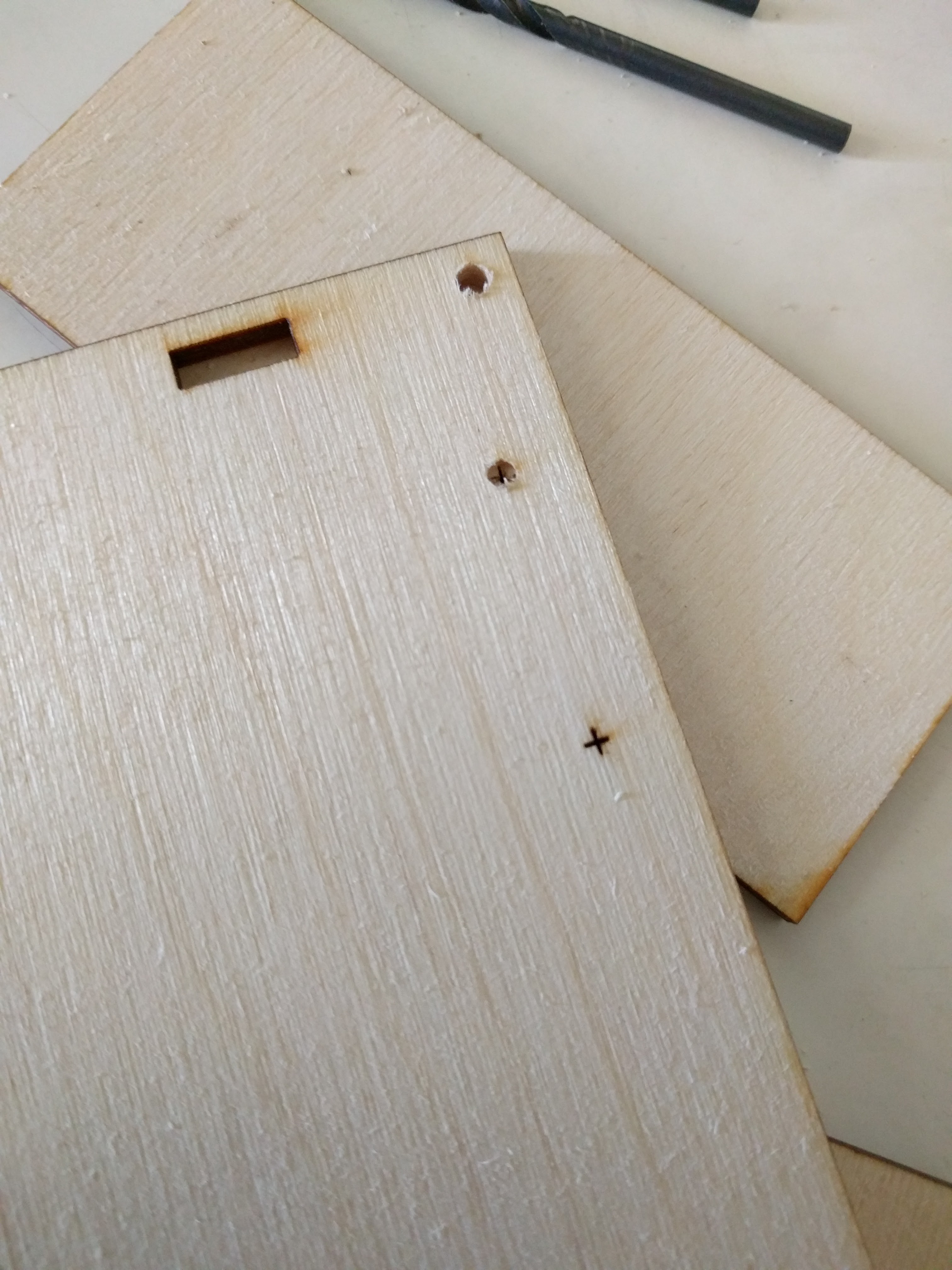 I had also been worried about the thickness of the material (which is 3.2 +/- .3 mm) and how that would work with the LCD support brackets, one slot which you can see above. I made them slightly bigger than 3.2mm, and everything fit just fine. I'll have to shim / glue it for it to really be secure, but that's not a big deal.
My final mistake I'm not really counting, but it is something I need to fix in the .svg file: I placed the screw guides for the LCD base about 0.5 mm to far out. I just drilled the holes a bit wider and everything worked fine.
My time is up for now, sorry for the short update. Next: the first version of the completed case.
I had stumbled upon Ponoko, a service that laser cuts a variety of materials to order. It seemed like a great way to put the case together. The short version: the end result is way better than anything I could have managed on my own, layout is a pain, and the service is pricier than one would expect.
Now the long version. With the basic idea of what I wanted sketched out and major issues like connector accessibility figured out, I thought that I was ready to go ahead and make the case for the RetroRiter. Early on, I decided to use Ponoko, which forced some decisions early on.
First of all: it gave me a timeline. I created a new account with thing (I am annoyed by the trend of forcing users to create accounts even to browse certain websites) while trying to learn more about the service. They sent me a $20 off code that had to be used in 10 days. So this gave me an incentive to layout the design and order it at the cost of doing a bit of a rushed job.
Picking Ponoko meant that I would be following their software recommendations: a vector based drawing program. Laser cutter instructions are encoded by the color of lines draw: blue lines 0.01 mm wide are cuts through the material, read means an engraved line. Gray fills are etched. This made getting started easy, especially since I am familiar with Inkscape. However, as the design was coming together I was soon wondering if learning an actual CAD program would be easier in the long run. Or maybe I need to learn more about Inkscape's features. For future projects, I think I would look around a bit to see if other options would have made my life easier, like easily being able to measure lines instead of calculating the difference between points all of the time. I don't know how much of the learning curve was from the inherit difficulty in the task or from using an inappropriate tool.
I also selected the case material earlier on: birch plywood. I thought the wood would lend more personality than acrylic and the birch plywood was a good mix of cheap and thickness. A note: the wood materials all seem to have a range of possible widths which could be problematic for making joints.
With this in mind, I set about laying out a .svg according to Ponoko's requirements (which is now in the github repo, but needs some fixes). This took a long time. Since the end cost factors in how long it takes the laser cutter, I did a few things to (maybe) cheapen things: corners were not rounded, small crosses mark screw locations (instead of cutting holes), and the left out any sort of engraved parts. The birch plywood only comes in two sizes: P1 and 1'x2'. P1 was too small, leaving me to use the larger size which was way too big. If I had more time I would have waited to add more parts to fill in the space, but I finally decided just to put the order in to keep the project rolling and take advantage of the $20 coupon.
However, the coupon only really covers shipping: the slowest option cost $19.96, making Ponoko's "make your first product for free" claim a little misleading. Shipping on the smaller P1 size for birch plywood was still about $17. Maybe other materials ship for less. Materials where $9.50 and cutting cost was about $12, so my end cost was just over twenty bucks. Which isn't bad. But I'm not sure I would have paid forty for it. I guess I'll have to figure something out for future jobs (recommendations welcome).
Next update: the laser cut pieces arrive and I realize all of my mistakes.
The RetroRiter needs a case. Or at a minimum some bits to keep it in a roughly ridged shape and keep the exposed PCBs protected.
When I had originally picked up the PiZero, I also got a case from C4Labs.net (the Zebra Zero... which seems discontinued but similar to the Nucleus Zero) along with a header (which I may regret as it adds bulk but makes prototyping easier... I might buy a second Pi Zero to use on the final product). The case looks nice, and there is something pleasing about the juxtaposition of a wood case for a PCB covered in solder and SMD components. I liked the screws that came with the Zebra Zero case, but couldn't figure out the size. Luckily C4 Labs responded to my cry for help on the twitter (size 4-40):
@10thMarshall they are 4-40 size stainless steel screws.
— C4 Labs (@theC4Labs) August">https://twitter.com/theC4Labs/status/760953386732707840">August 3, 2016
So the Pi Zero is protected and can be secured. The next part of concern is the HDMI display. For this, I decided to order a bunch of hex standoffs from Amazon to play around with. They are great to prototype with, look cool in bronze, and give a lot of flexibility in sizing. My initial plan was to make the computer as a sandwich: plywood baseplate and display as the bread, with the Pi Zero and whatever else as the meat. The standoffs would secure the display to the base, and let me play around with the spacing. Here's a shot of the display with M3 (I think) standoffs:
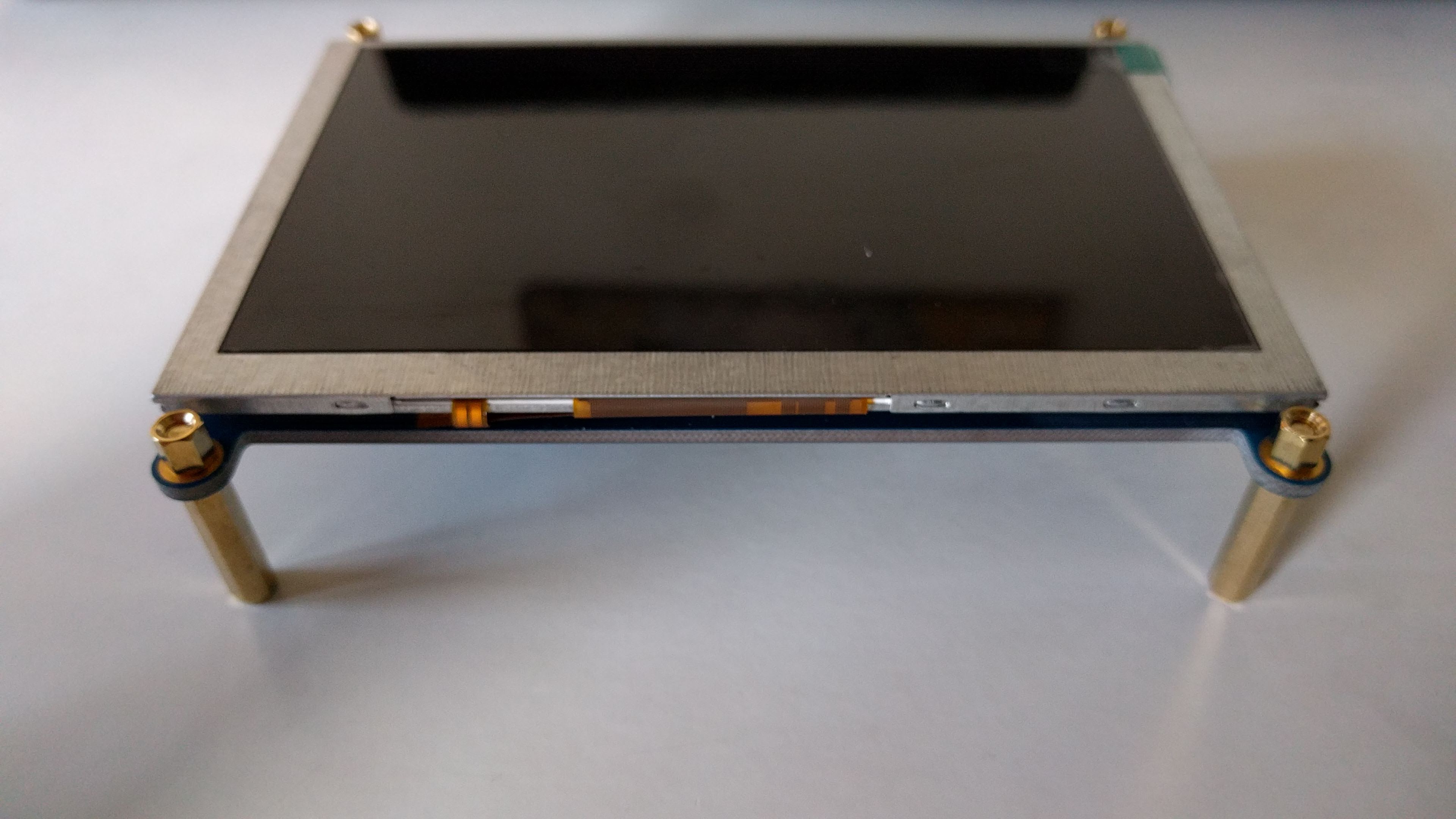
I played around with the spacing a bit. Early on I had realized that I needed a shorter HDMI cable, so I also ordered a 1' cable which seems to work alright. I couldn't find a flat one, and I probably should have gotten one with a 90 degree angled connector for the display side, but I'll deal with that later. The current one is workable.
From here I started to lay everything out and tracing the component outlines onto paper as a first step for designing the base. Things became a bit more complicated because I realized for usability the display should be angled towards the user. I briefly considered a hinged design, but abandoned it as too complicated. This step also revealed that to use the USB hub with the Pi Zero, I need to orientate the Pi to accommodate the hub's short cable, at least if I want the hub to fit snug along the bottom of the display. Here's what the rough sketch looks like:
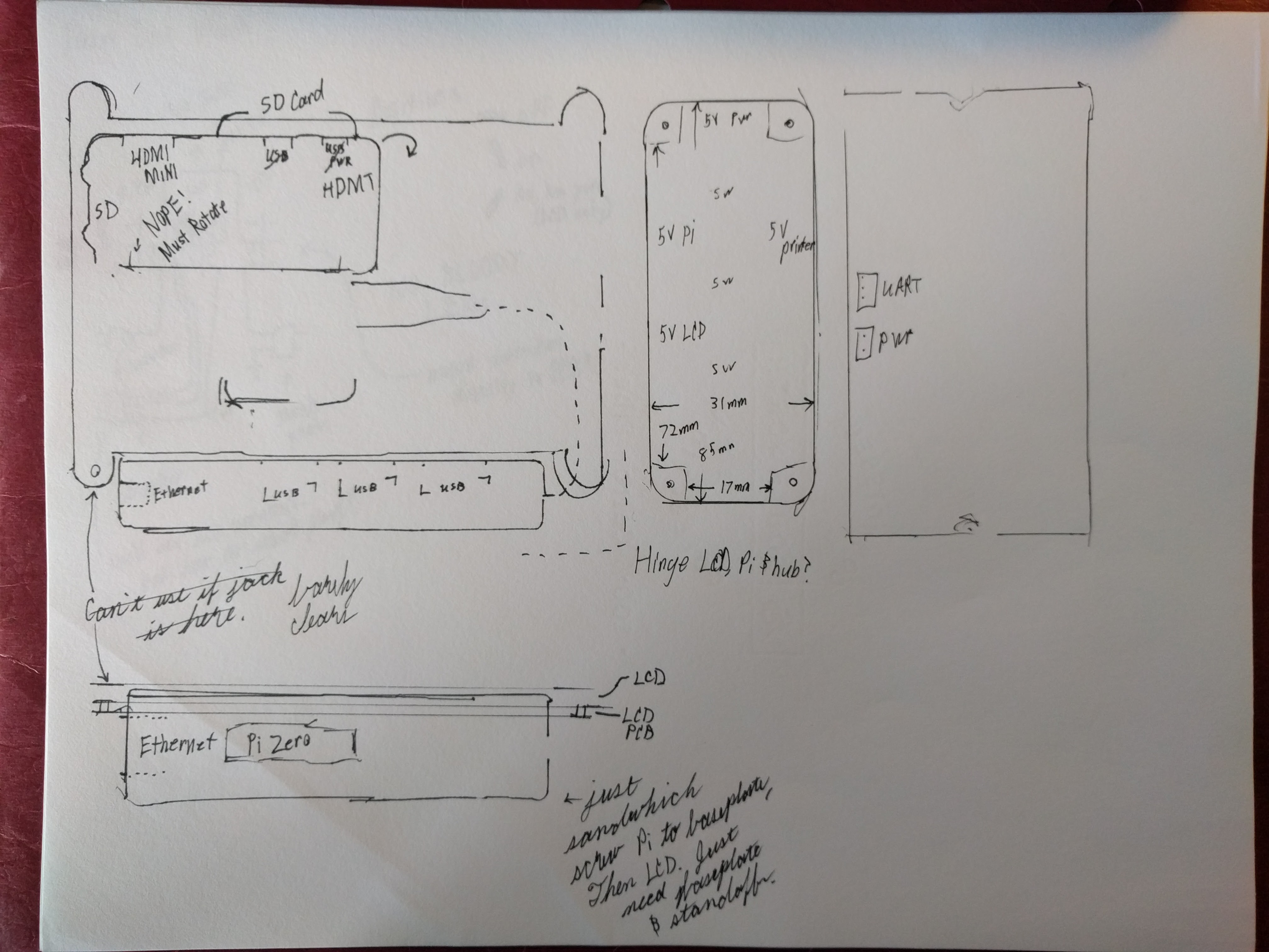
Note the "Nope! Must Rotate." I'm glad I saw that problem early. The outline used for the power distribution box is that of the aluminum box I threw onto my Amazon order to push it over the $50 shipping limit. It looks like it will work great... unfortunately I don't have any metal working tools or experience. In this diagram I tried to also capture relevant connectors / access points. For example, I'm going to orientate the Pi so that the SD card sticks out of the top of the display.
Next steps will be to design the base parts and order them.
Given my tendency to start but not finish projects, I have made a good deal of progress on this project without making any updates. Now that the project is rolling and I think I'll actually finish, I'm going to start posting updates as if I had actually done them from the start.
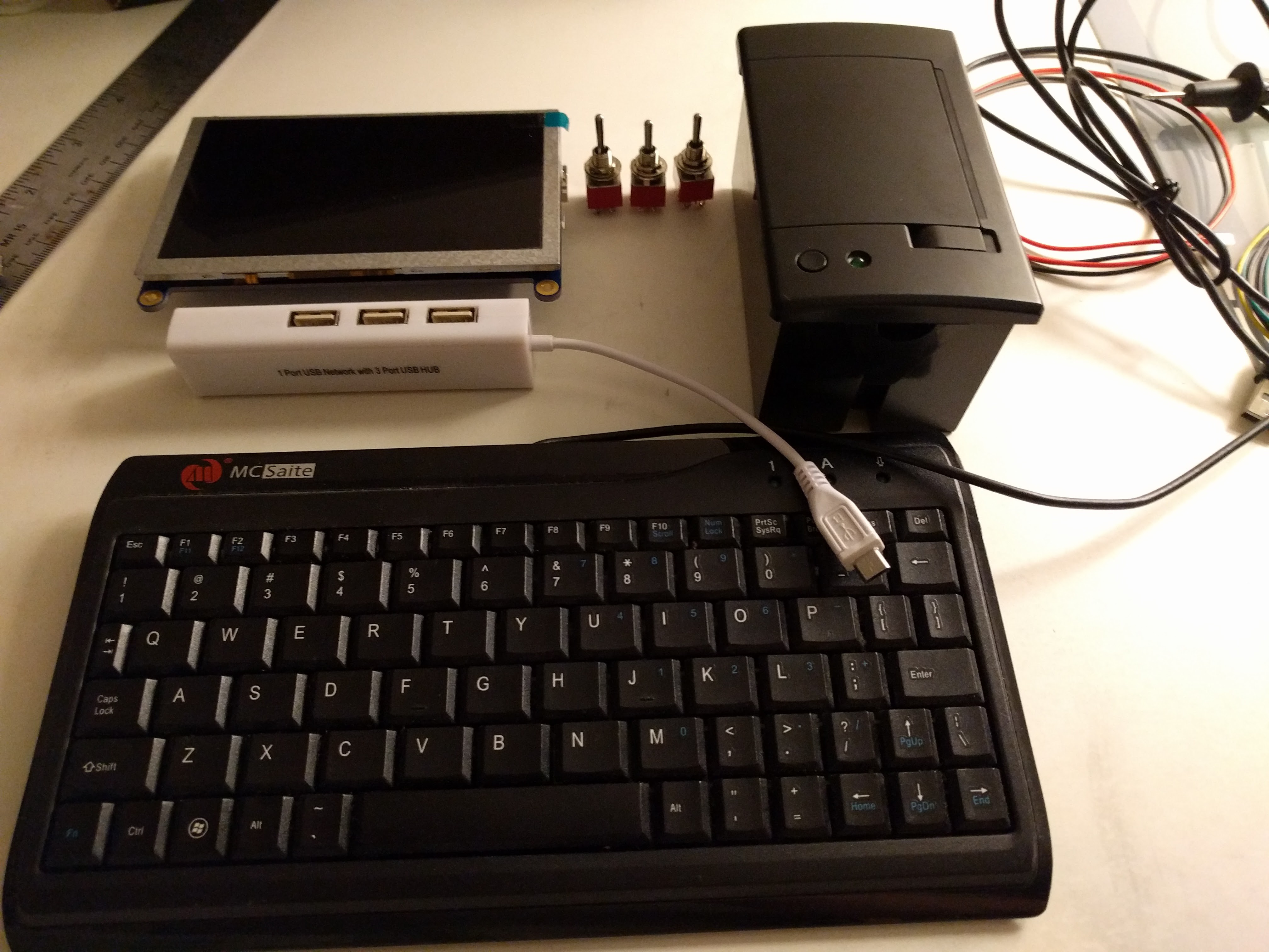
This inspiration for this project is a pile of cool stuff (okay, mainly the printer) and a compulsion to finish something before buying any more cool stuff. I decided to purchase a 5" HDMI display because of difficulties I had in working with E-Ink displays in the past which are due in part to my incompetence but also the fundamental differences in their functionality and the needs of a computer display (static display with slow refresh vs. constantly updating). I haven't given up on E-Ink... just for this project it's nice to have a display done and working (albeit with a $60 price tag plus cable). The printer, display, a USB hub and a keyboard make the core of the system, pictured below (missing the Pi Zero):
The next big question is how to connect it all together. Data: HDMI to LCD, UART to printer, and USB for everything else. Power: while the display and Pi can both be run on 5V via USB, this adds a lot of cables. The printer also uses 5V, but at least 1.5A, so more than USB can provide normally. This led me to the conclusion that I need to make a "power distribution" module... which is an excellent place to put switches. Switches are necessary.
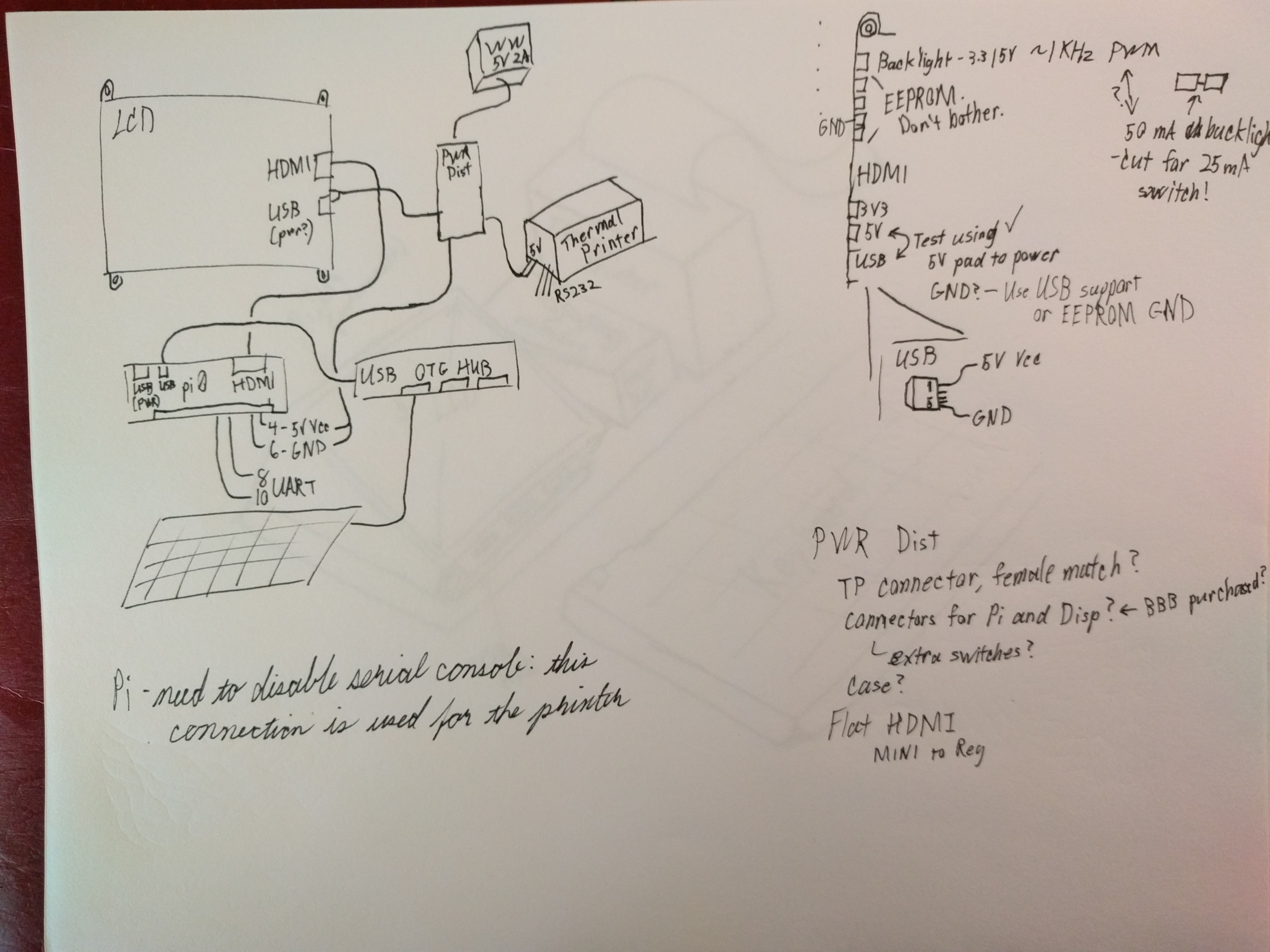
This sketch shows the relevant connections for each component. I also checked the pin outs / docs to make sure I could supply power over various pins and pads instead of USB cables. Oh, and I picked up a 5V 2A wall wart to provide power.
So, at this point I have a pile of parts and some idea of how they are going to go together. The next steps are going to be the physical layout / case, and the design of the power distribution box.
Create an account to leave a comment. Already have an account? Log In.
Become a member to follow this project and never miss any updates
By using our website and services, you expressly agree to the placement of our performance, functionality, and advertising cookies. Learn More
 timonsku
 Tom Nardi
 Dan Jilek