Mark Bradshaw
-
Mechanical tester gets a UI
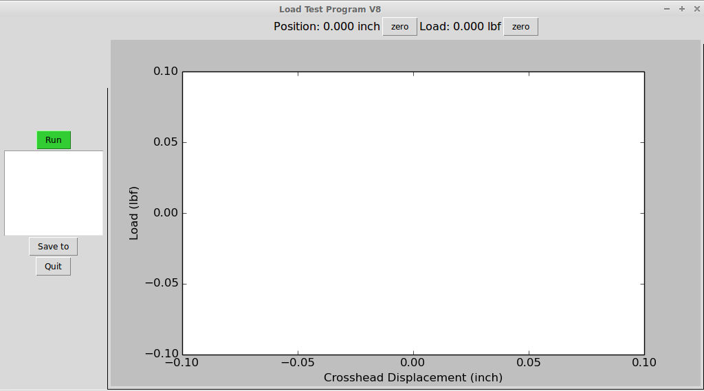
11/04/2016 at 18:44 • 0 commentsThis project needs a basic user-interface that can do a few things:
- Convert the data from a raw count into calibrated units
- Hit a button to begin recording data
- Hit a button to stop recording data
- Display the data in real time as it is collected
- Save the data as a csv file with some comments about the sample
For the UI I am using Tk with Python because I have a little bit of experience with it from when I was reading out images from my scanning electron microscope. I picked it in that case because it is sort of the default Python toolkit.
![]()
As of right now the UI is in the working prototype stage. It does all the stuff I need it to but it could use some more flexibility in the 'save as' command or selecting different calibration values.
-
Reading serial data with Python
11/03/2016 at 14:58 • 0 commentsAt this point in the project I've given some brief descriptions of how the Arduino is reading the digital signals from the quadrature encoder that measures position and the analog output of the load cell. These data are then written to the serial port as the string "POSITION LOAD\n"
where POSITION and LOAD are integers with the current values. So at this point I need to receive the serial data on the computer that is going to display and store the data for me and this is where things get a little hack-ish.I found some helpful information on how to read serial data in Python from the project "Arduino Monitor" by Greg Pinero [1]. The approach is to have the serial-data-reading-class spawn a worker thread that is continuously reading the serial port and storing the data to a variable. The value in this variable is always the most up to date data received. The class will then return that value whenever polled by the main program. Sounds good so far.
I ran into a few problems, first is I am reading two channels of data, this is relatively simple to fix. First the string is broken up into two string variables for position and load using the string.split() command. Then those strings are returned as a tuple of integers by the command return (int(x), int(y) ).
More problematic for me has been that the worker thread does not always want to die. This has been mostly handled by adding a flag to the worker thread's loop:
while keep_going:
    read serial data and store it to variable
Then setting keep_going to False makes the thread die, great. But if there is an exception somewhere else in the program and it crashes then the thread stays... alive... forever... until I kill the process. -
Signal conditioning of analog input
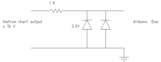
11/01/2016 at 13:35 • 0 commentsThe output of the load cell, the force sensing part of the instrument, is a +/- 10 V analog signal available at the chart recorder output. Prior to getting there it goes through a series of demodulation and gain stages that I will elaborate on later. The Arduino Due can only accept a 0 - 3.3 V signal so I had a choice of either rescale the signal or clip the signal to levels that are safe for the microcontroller. I chose that latter because there is a final amp with selectable gain that give me plenty of leeway to change the scale, I just need to make sure the signal doesn't damage the Arduino.
To clip the output I'm using the circuit shown in the figure. The positive output is clipped by the 3.3V zener diode with a 1K resistor to limit the current. One more diode was required because the forward voltage drop of the zener actually exceeded the allowable negative voltage of the Arduino.
![]()
-
Arduino Due reads encoder
10/27/2016 at 15:21 • 0 commentsIn the last post I described how the Instron 1000 main board is taking the two encoder signals and their inverted twins and mixing and buffering them to reduce noise. The resulting two signals have a normal two wire rotary encoder pattern and can be measured like any other encoder but first they need to be shifted from 12V logic at the Instron to 3V for the Arduino Due.
To shift the signals I am using a Sparkfun BOB-12009 logic level converter. It's overkill for this maybe but it is easy to use, the 12V logic and 12V power are connected on one side and 3V from the Arduino supply is connected to the other side with connections to the Arduino digital input pins.
The Arduino code was a little trickier. At first I tried using the Encoder library by Paul Stoffregen which can be accessed through the Arduinoo IDE library manager. The library looks great but I found I was losing steps even at low speeds no matter what optimizations I flipped on or off. The encoder on this machine really hums along, I measure about 162500 steps / Inch, with crosshead travel able to go up to about 20 inch / min thats about 55,000 steps per second. As I searched for some more options I happened to find that the Arduino Due actually has a hardware encoder! This thread on the Arduino forum was really helpful [1] with a few examples. I mashed those a bit and wound up with this minimal code:
void setup() {
  // Setup the quadrature encoder
  // For more information see http://forum.arduino.cc/index.php?topic=140205.30
  REG_PMC_PCER0 = PMC_PCER0_PID27;   // activate clock for TC0
  REG_TC0_CMR0 = TC_CMR_TCCLKS_XC0;  // select XC0 as clock source

  // activate quadrature encoder and position measure mode, no filters
  REG_TC0_BMR = TC_BMR_QDEN
              | TC_BMR_POSEN
              | TC_BMR_EDGPHA;

  // enable the clock (CLKEN=1) and reset the counter (SWTRG=1)
  REG_TC0_CCR0 = TC_CCR_CLKEN | TC_CCR_SWTRG;
}

// The encoder position is then accessed from
void loop() {
  int newPosition = REG_TC0_CV0; // Read the encoder position from register
}
and this has been totally solid. I put this value out over the serial connection periodically where the computer can read it. -
Encoder Logic
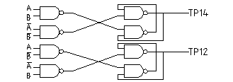
10/20/2016 at 16:14 • 0 commentsThis machine uses a 4-wire incremental rotary encoder instead of the often seen 2-wire encoder. There are 2 signal wires (A, B) and 2 inverted signal wires (not A, not B) in addition there are Z and not-Z signal that are not used. So to read the encoder position I could simply not use the inverted signals and be done with it, but the machine is noisy and vibrates so the additional noise rejection could be helpful. If the engineers at Instron thought it was important then I'm not going to question them. So I thought it would be interesting how they used these additional two inverted signals.I followed the encoder signal traces from where they enter the main board and found they all end up at two chips, U33 and U34, which are both MB14011B quad 2-input NAND gates. Following the other traces showed a circuit with the following configuration:
![]()
NAND is a logical operator meaning not(X and Y) and is represented by the blocks with a round side with the circle on it. NAND has the following truth table:
A B NAND( A, B ) 0 0 1 0 1 1 1 0 1 1 1 0 If you continue to follow the logic of the circuit you will find that the two pairs of NAND gates of the right side of this circuit have some interesting behavior in that in certain cases the output depends on what the previous output was. This circuit is known as a SR NAND latch and you can find more information about it on wikipedia here: SR NAND Latch.
This circuit takes the 4 encoder signals as inputs and produces 2 outputs accessible at test points TP12 and TP14. Looking at the logic of the complete circuit reveals the nature of the signals at TP12 and TP14.
For simplicity I have assumed that not(A) and not(B) are always correct so no noise.
Clockwise Continuous Phase A B TP14 TP12 TP14 TP12 1 0 0 0 No Change 0 1 2 0 1 No Change 0 0 0 3 1 1 1 No Change 1 0 4 1 0 No Change 1 1 1 CCW Continuous Phase A B TP14 TP12 TP14 TP12 1 1 0 No Change 1 0 1 2 1 1 1 No Change 1 1 3 0 1 No Change 0 1 0 4 0 0 0 No Change 0 0 The output of the circuit is simply the normal 2-wire encoder output however it will not register most cases where one signal changes but it's inverted pair does not. I can use leads to TP12 and TP14 as if they were normal encoder outputs.
-
Dog eats lab notebook
10/20/2016 at 14:54 • 0 commentsMy furry lab assistant got on the desk and tore this project's delicious lab notebook apart. Luckily I was able to salvage the information with scotch tape and a photocopier. I need to start scanning pages as I make them to ward off any future data loss.
![]()
Load Frame Update
Add digital output to a mechanical testing load frame using arduino.