 Lucas BROGLIO
-
1First step : Arduino part
1st of all we decided to use a photoresistance in order to collect the ambiant light.
Furthermore we are using a led strip of 12V so we needed to put a transistor.
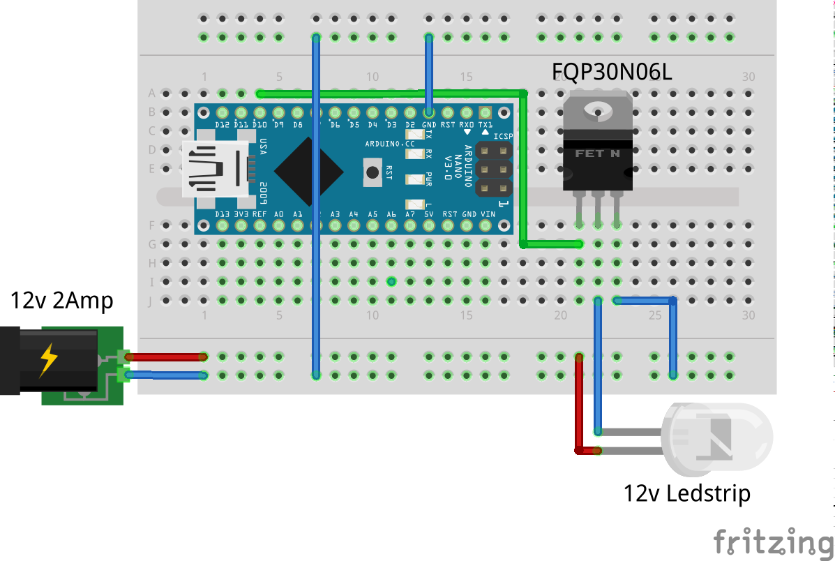
We followed the following scheme.
![]()
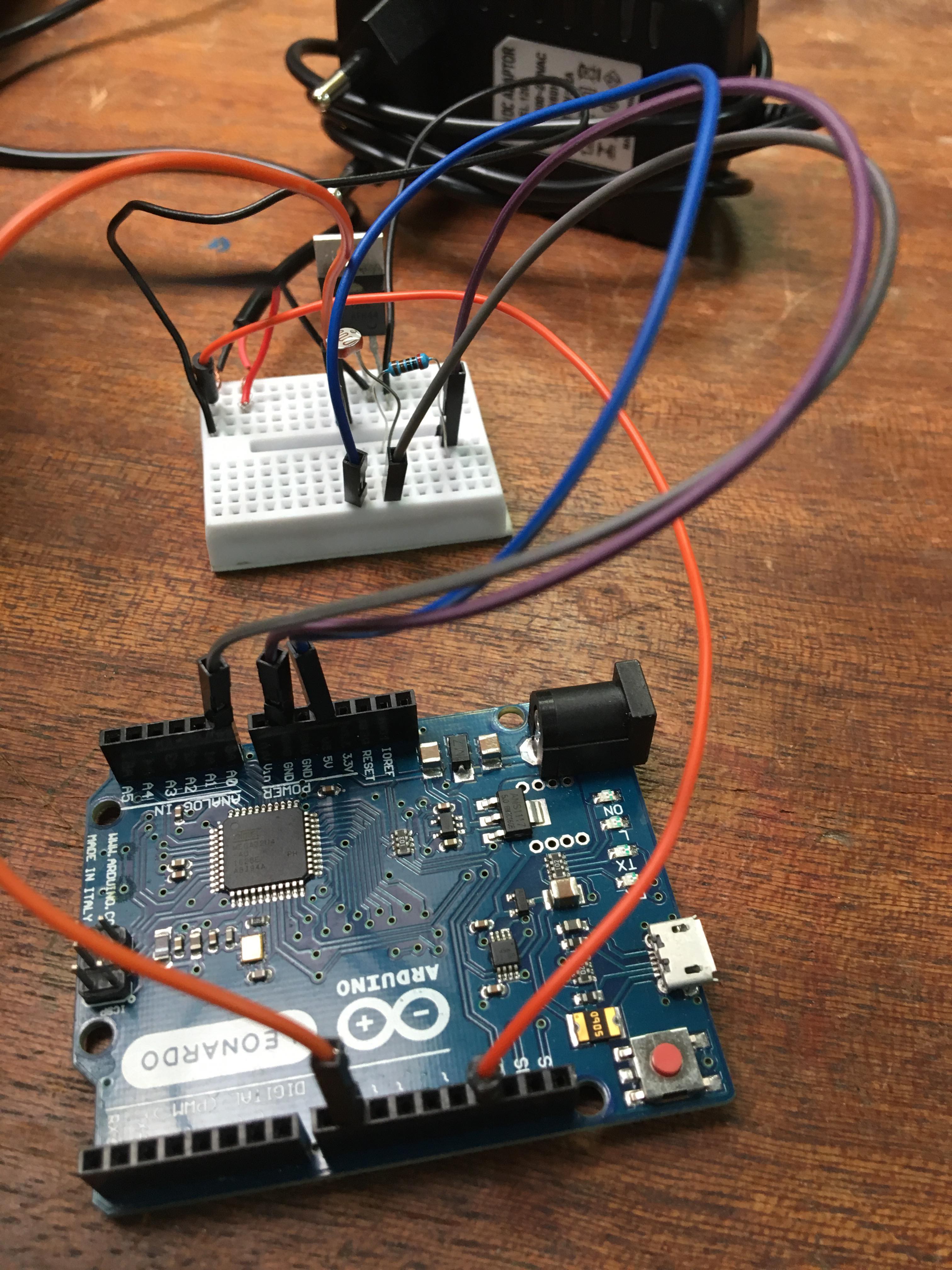
We add at this scheme the photoresistance.
If you want to create the same thing as we did follow the cable management.
![]()
-
22nd step : Code
int led = 9; // the PWM pin the LED is attached to
int brightness = 0; // how bright the LED is
int fadeAmount = 100000000; // how many points to fade the LED by
int photocellPin = 0; // the cell and 10K pulldown are connected to a0
int photocellReading;// the setup routine runs once when you press reset:
void setup() {
// declare pin 9 to be an output:
pinMode(led, OUTPUT);
Serial.begin(9600);
}// the loop routine runs over and over again forever:
void loop() {
// set the brightness of pin 9:
analogWrite(led, brightness);// change the brightness for next time through the loop:
brightness = brightness + fadeAmount;// reverse the direction of the fading at the ends of the fade:
if (brightness <= 0 || brightness >= 255) {
fadeAmount = -fadeAmount;photocellReading = analogRead(photocellPin);
Serial.print("Analog reading = ");
Serial.print(photocellReading); // the raw analog reading
// We'll have a few threshholds, qualitatively determined
if (photocellReading < 200) {
Serial.println(" - Dark");
brightness = 255;
} else if (photocellReading < 500) {
Serial.println(" - Light");
brightness = 100;
} else if (photocellReading < 600 ) {
Serial.println(" - Luminous");
brightness = 50;} else if (photocellReading < 700 ) {
Serial.println(" - More luminous");
brightness = 20;
} else {
Serial.println(" - Very bright");
brightness = 0;
}
Serial.print(brightness );
delay(5);
}
// wait for 30 milliseconds to see the dimming effect
delay(30);
}
Adaptive Lighting
We want to create a simple system which would regulate the intensity of interior lighting depending on the amount of sunlight coming in.
Discussions
Become a Hackaday.io Member
Create an account to leave a comment. Already have an account? Log In.