-
after 5th prototype
07/26/2017 at 13:18 • 0 commentsAfter 5 prototypes built and field-tested, here are the conclusions.
One thing wrong with our hardware setup was battery: a half-empty 1200 mAh battery doesn't give enough juice to power-up SIM 808. So we upgraded to 4400 mAh, and our device became fully self-sufficient.
A few bugs in firmware fixed, wake-up timer set to 4-hour period.
There's a couple of bad things specific to GSM networks and modules though.
While we cannot do anything to fix them, we can do a couple of things to live with them.First of all, SIM cards have PINs. Makes sense for human-operated devices, but for stand-alone self-sufficient things, not so much. Bottom line, PIN has to be hardcoded in the firmware. Easiest way to get rid of PIN is to insert SIM into a smart phone and disable the PIN, exact steps are specific to device model.
Then, we used prepaid SIM cards of various mobile operators, and they all wasted all available credits on very first day.
You wouldn't expect sending a few kB of HTTP requests cost a few EUR eh?
Well, that's how bastards steal from their customers: you have to register SIM for data traffic, or else!
Registration itself is sending a specific SMS from device containing SIM card to some proprietary number.Again, do that while SIM is in your phone.
But of course, that kind of issues is why we have LoRa and Sigfox and stuff.
In our case, GPS is must have, and HTTP is very nice to have, and SIM 808 has them both.
That would be all for the time being. You may still hear from us improving software eventually.
-
Steps towards a commercially viable device
12/06/2016 at 13:05 • 0 commentsOver the past few weeks, both good and bad things about the current hardware configuration of ecotron became apparent. Electronics turned out to be very reliable, method of mounting the thing into actual trash cans proved vital for our long-term mental health, power turned out to be a big issue.
During the summer, I conclude, the device could operate for long periods of time, but as the days grow shorter and sun drops lower, the amount of power our solar panel collects just isn't enough to cover for the losses in idling hardware. I've tried to minimize the idle current, but down to about 10-15mA is as low as I dropped with the current hardware. The pieces used just aren't meant for low power applications, so saving power would require a complete redesign of the device. This has to, and will happen at some point in the future, but not immediately.
Furthermore, since the battery chosen for testing purposes barely cuts the peak current draw, choosing a bigger one with more leeway in maximum current is a must. To make up for the idle power loss, choosing a bigger solar panel will work as a band-aid solution.
-
Stalker 3.1 testing
11/02/2016 at 11:56 • 0 commentsAfter running the device over the weekend, sending reports every hour, we finally got some battery data from the new Stalker 3.1. While there is a noticeable improvement (roughly 25%), taking into account the effect of our solar panel during cloudy weather, we were still losing 0.66% battery per hour on average. During the summer, we'd easily make up for lost power via solar, but it just won't suffice in these long winter days.
That said, we are yet to test where the power loss is coming from on the new board - for all we know it could be mostly sending! More data coming soon.
![]()
-
Back to work!
10/19/2016 at 10:11 • 0 commentsHooraaay, we just received new stalkers!
And, our friends from Veta started making enclosure for our electronics.
We'll be back soon with more news, in the meantime, check out how box making looks like: -
Conclusions for now
09/29/2016 at 12:52 • 0 commentsAfter two months of on and off development, we decided to put this project on hold. The entire code base for our system is in place - with minor adjustments and quality of life improvements, it is a finished product. Our hardware, however, is not up to the task. It was and still is great for prototyping and testing and we learned a lot in the process, but the parts used are simply not tailored for this design.
We came to a conclusion that, should we continue to develop the hardware, a custom-made pcb with strict power control is a must. Design as it is is simply sub-optimal and we can do better. We will try out the new v3.1 of the stalker board though, as an intermediate step.
A big part of why our tests didn't go as far as we thought they would turned out to be the base for it all - the Seeeduino stalker. A while back, they offered a great deal - v3.0 stalkers 70% off. That's when we got this board. It was sitting in the office unused until we picked it up for it's fabled efficiency in outdoor applications... But it turns out there's a story behind why they were 70% off - a series of poor design choices including a cheaper RTC chip without temperature compensation (quite disastrous for any long-term applications though that doesn't bother us too much because we can readjust it from the server) and a poorly optimized regulator which burns over 3mA under certain loads. This burn happened to hit us while the device was in idle state, greatly hurting its battery life.
Reading around about the stalker 3.0, it turns out we were not the only ones unhappy with what they did with the board. It's not terrible, but at some point, we will have to part with it for a better solution.
Graph below shows our enthusiasm for hardware used.![]()
It actually plots battery charge % over 3 days. Green humps are times when battery was being charged by the solar cells.
-
It's all turned off
09/13/2016 at 10:35 • 0 commentsAfter trying out some switching transistors, I settled for 2SJ200 - a lovely, though somewhat expensive switching P-FET. I made this choice mainly due to its very low switching treshold - it is important we achieve saturation when switching 3.3v with 3.3v control signal (refer to Vds and Vgs on 1st figure on page 3 of datasheet). Power-wise, this FET is significantly over the top, but it is the best one that works and is readily available at this point. Later down the road we may replace it with a cheaper one.
It is very important that for this particular application, P-FET be used as arduino signal pins can (and will!) ground. Since positive supply line is common, it only makes sense to put the switch there.
Initial tests have shown no problems, and a long-term test is already underway. Look forward to pretty pictures!
-
We're still leaking current
09/09/2016 at 09:43 • 0 commentsSo after shutting down sim808 and putting the stalker to sleep, results improved somewhat... But the improvement was just not good enough for what we expected. Measuring current draw from the battery yields a whooping 15mA - what in the world could be causing this?
The one thing we never suspected would dissipate much power when left unused - HC-SR04. The idle current we measure amounts to anywhere between 2.5 and 2.6mA, and since we got 5 of them, as well as a temperature sensor which leaks 0.6mA, things quickly get out of hand.
It is obvious that these sensors must also be turned on and off on demand. For this, we need an efficient, low power electronic switch. No such thing built in, of course, so we decided to hack one in ourselves.
The plan is simple - install a mosfet (2N7000) switch between the stalker 3.3v power output and the sensor shield power input pins, and control it using arduino pin 3 (literally the last free pin we got).
With this in place, we expect to drop down to 1mA ranges and finally be fully viable as a self-sufficient device with low maintenance cost.
-
Some battery tests
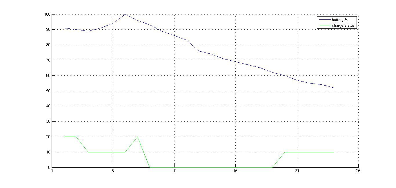
09/06/2016 at 09:57 • 0 commentsFinally the sleep code is up and running. I've set the device to power on every hour and do its full sending cycle to test battery life. Here's what the time span from yesterday afternoon until this morning looks like.
![]()
The green line on the bottom indicates whether the battery is charing (10), not charging (0), or full (20).
Weather is pretty bad too, so these are truly ideal test conditions. It seems that per hour, around 2% battery is lost. Next thing to determine is whether (or rather, how much of) this loss comes from the sending process (great result) or idle state (not so great result). This will be tested by gradually increasing the sending interval and comparing results for different intervals.
Another possible issue I've noticed is that solar panel wakes up the sim808 module from time to time due to its reaction to getting power over USB. It could be that the module still chugs down current instead of staying put when we finish sending.
-
Trash can's new brain
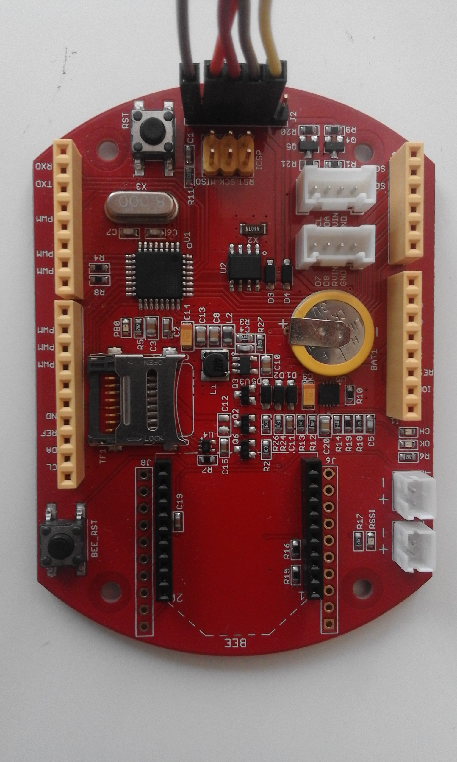
08/31/2016 at 12:40 • 0 commentsRealizing that using a vanilla-ish arduino board will not yield good energy savings without heavy modding, we opted for a slightly more expensive, but function-packed option: Seeduino Stalker. The one we have is v3.0, arguably the windows 98 of the whole Stalker series according to some reviews. Thus far we encountered no problems migrating to the new, frugal platform. In fact, we were given a built-in RTC and power circuitry designed for a li-po battery from the get-go.
![]()
The best part about this migration is that, save for moving one pin to free the I2C interface, it is perfectly compatible with the sensor shield we used with Iteaduino. A pretty small price to pay for literally 100 times less idle current draw at 3V and a built-in RTC ready to send wakeup interrupts.
Coming up next: more detailed power consumption measurements, full-fledged sleep mode.
-
And then we ran out of power
08/29/2016 at 09:41 • 0 commentsAfter finally getting to play with our device for longer periods of time, we noticed that, while the battery does charge itself more than enough to send reports and stay up during the sunny summer days, our device tends to go down with the sun.
Obviously, this is a problem.
We were quick to choose a prototyping platform such as Arduino, in fact a clone of it, for a project that requires low idle power consumption. Some tests later, we realized that the USB to serial chip, as well as its regulator (okay we saw that one coming) take away quite a bit of current in their idle state. The sim808 module is unsurprisingly a big spender too, but since that one can be turned off, we don't really mind.
At 3V supply (low limit), our Arduino managed to pull 77mA through its step-up circuit and down its regulator. Now, obviously this isn't really the circuitry one would want in an efficient project, but we needed stability, and we needed it fast.
The step-up itself wastes around 13mA when idle, and sim808 drains about 35mA when idle and unconnected.
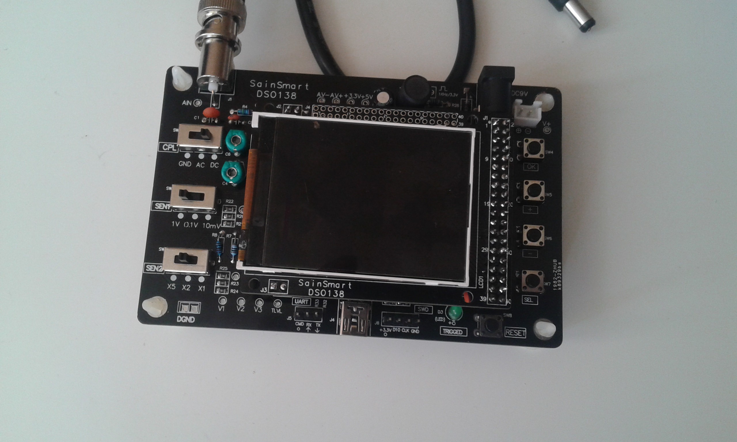
On top of our simple multimeter tests (warning, digression incoming), I assembled some oscilloscope kit on a whim, so we tried using that to check the variations in input voltages.
![]()
Going full zen, I sat down, measured and sorted all the components and let the soldering iron heat up. A few hours and a dozen google pages later, I found out that I'm not actually bad at soldering, but that there's a couple of jumpers the user is supposed to short on the board. But you know, real men don't read manuals. So now that we had a working oscilloscope, and for the price and amount of effort, it's actually pretty impressive, I monitored supply voltage and found out some interesting things. But let's save those for when I have some pictures, or when I figure out how to draw data out of this baby into the PC.
But here's where it gets interesting. See the logo in the top left that says SainSmart? Well, we had pretty bad experience with their stuff before so when I assembled this and it worked like a charm, I was honestly surprised and impressed! Well, no wonder it works like a charm when they're not the ones who made it! Sneaky schmucks.
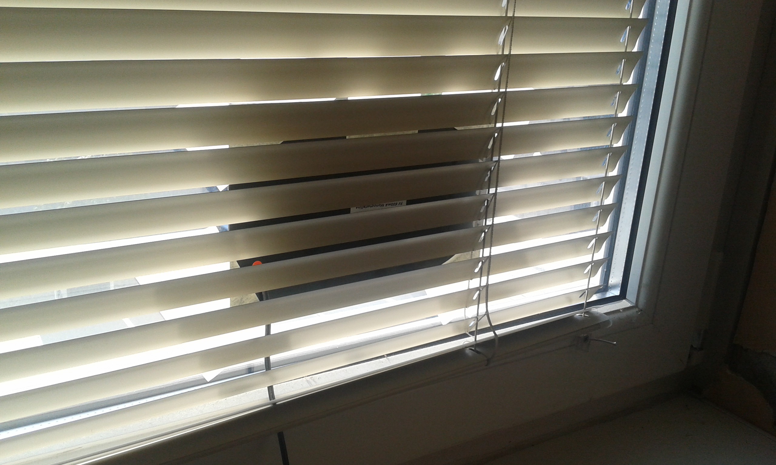
This is our professional solar plant setup by the way.
![]()
Such sleek design. It actually does serve a purpose - it simulates poor real-world conditions.
So now we need to come up with a way to keep the devices stable by keeping voltages tamed, while dodging the regulators and all this wasteful circuitry.
 mikrotron