Close
0%
0%

Traffic Signal LED Matrix Display

A networked LED matrix display made from a surplus LED traffic signal

Similar projects worth following
Wanting to make something from a surplus LED traffic light, I realized that one could be re-wired as an LED matrix. Despite the unusual geometry of this matrix, I thought this would be a perfect excuse to play with lots of LEDs and an ESP8266.

An LED traffic signal, converted to a battery-powered, LED matrix controlled by an ESP8266. The controller is derived from an Adafruit Feather HUZZAH, but generally allowing higher currents, and with no built-in USB-to-UART chip. The LED matrix is driven by an STP24DP05 constant-current LED driver. The ESP8266 runs MicroPython, allowing easy development and testing.

traffic_light_battery_holder.zip

Battery holder for the traffic light's LiPo battery. It can probably be adapted to most LiPo batteries, but the specific battery this was modeled for can be found here: https://www.adafruit.com/products/328

x-zip - 11.69 kB - 08/18/2016 at 19:39

Download

  • 1 × 12" traffic signal, hexagonal grid layout, 13 rows Can be found cheap from government surplus.
  • 1 × ESP-07 module with external antenna
  • 1 × 3D-printed battery holder OpenSCAD source and STL can be found in the Files section
  • 1000000 × Other things I haven't entered in here yet Yeah, it's got, like, a million parts.

  • The Promised Software Post

    Clara Hobbs08/21/2016 at 15:53 0 comments

    I've uploaded the software, for both the ESP8266 and server, to GitHub. You can download it here. As of now, I have a basic display driving module that is used to show static images loaded from PNGs or PBMs. PBM loading is handled directly from the TrafficDisplay class, while PNG loading is done by my new micropython-png module. You can set the speed at which the display refreshes in milliseconds. I find that 2 ms per row is a decent speed: while it is noticeably flashy, it's not too obnoxious, and it doesn't look terrible when a network connection is active. 1 ms looks much better (as long as the processor is clocked at 160 MHz, which it automatically switches to if you set the display to run at 1 ms per row), but rows have inconsistent brightness when a network connection is active. I suspect the dual-core ESP32 would solve the problem entirely: I could run the matrix driving code on one core, and everything else on the other.

    In the software repository you can also find a weather display application, with both a server and microcontroller component. The server component fetches current weather information from forecast.io and strips out everything the ESP doesn't need. A single call to forecast.io's API gives around 25 KiB of JSON, which the ESP would have a hard time processing all at once. By extracting only what we care about for the application, the ESP8266 has a much easier job. All it has to do is fetch the trimmed weather information, load the right PNG from its filesystem, and display it on the LED matrix. In the future, I'd like to make the icons animated, which would probably make it easier to tell what they're trying to depict. I'd also like to be able to show more interesting weather information, such as temperature and humidity, and maybe a forecast for the next couple days. I'll keep working on it, so stay tuned!

  • 128 Mb Flash + MicroPython = ???

    Clara Hobbs08/19/2016 at 17:29 3 comments

    My 128 Mb flash chips arrived in the mail today. I quickly soldered one onto the ESP-07 module, and found that MicroPython doesn't seem to like having 128 Mb of flash. It works just fine if I set the flash size to 32 Mb when flashing, but only being able to use ¼ of my shiny new flash chip is disappointing. I'll try to figure out how to fix it soon, and if I succeed, I guess I'll have a pull request to send.

  • It's alive!

    Clara Hobbs08/18/2016 at 19:16 0 comments

    The North Carolina State Surplus Property Agency warehouse in Raleigh usually has several huge bins full of LED traffic lights for sale for $3 each. With each light containing over a hundred LEDs, that's a fantastically low price for the LEDs alone. The cheapest green LEDs I can find at Mouser still cost more per diode at quantity 5000 than these surplus traffic lights. The only problem was that I had no use for a hundred or so LEDs, so I went home empty-handed. A couple weeks later, I finally came up with a use for one of those traffic lights: re-wiring it as an LED matrix. Two trips to the surplus property warehouse later (the first light had some bad LEDs, so I went back to get a second one to replace the bad ones, only to find that the second one didn't have any bad LEDs), I set to work.

    Shrinking the matrix from 13×13 to 12×12

    After opening the good traffic light, I cut nearly all the traces on the LED circuit board. Then I wired the anodes in rows and the cathodes in columns, joining the first and last row and column together to shrink the matrix from 13×13 to 12×12. Saving pins in this way seemed like a good idea, even though at this point I had no concrete plans on how to actually drive this matrix. The traffic light sat in this condition for a couple months with no further progress.

    Then, one day I saw the ESP8266 MicroPython Contest, and thought it seemed like the perfect excuse to finish the traffic signal LED matrix. I looked at available ESP8266 modules, and thought the Adafruit Feather HUZZAH seemed like a good choice. Then I looked at it in more detail and started seeing where things would go wrong. Its voltage regulator could only supply 600 mA, which isn't a comfortably large amount for running an ESP8266 and my LED matrix. Also, while the battery charging seemed nice, I didn't like that it was charging from USB, and could only charge with 100 mA (unless I changed a resistor and figured out how to ask the host if drawing 500 mA is okay). I wanted to use a 2500 mAh battery so I could run the system for several hours on a single charge, and having to charge it for a whole day didn't sound very good. I also wanted an external antenna, which the ESP-12 module doesn't allow.

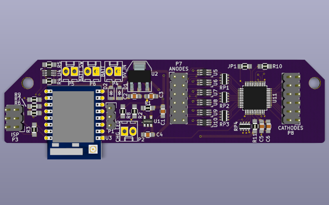
    Traffic signal LED matrix controller PCB

    I decided to make my own board based on the Feather HUZZAH, but fixing its shortcomings for this particular application. I used a 1A voltage regulator, a barrel jack for power, and a UART header for programming rather than an on-board USB-to-UART chip (sorry about the weird pinout, it matches some other boards I already had). The battery charger is the same as the one on the Feather HUZZAH, but configured for 500 mA charging current. I also used an ESP-07 module so I could use an external antenna. After some research, I found the STP24DP05 LED driver chip. Using some external PNP transistors, it allows me to drive the whole matrix at a constant 20 mA per LED. I made the board with KiCad, ordered the parts from Mouser and the boards from OSH Park, and in a couple weeks I put it together. Much to my surprise, there were no mistakes in the board despite how many parts I had to hand-copy from datasheets into KiCad.

    I finished building the board Monday afternoon, and I've been hacking the software since then. MicroPython makes the development pretty easy, but it's not really capable of driving the display as fast as I'd like. It works pretty well at 41 ⅔ Hz, but it's noticeably "flashy". I've written code to load PBM images, which are perfect for this kind of display because the files are tiny, they have just 1 bit per pixel, and I can draw them with The GIMP. I'll write more about the software I've written for it in the next post.

View all 3 project logs

  • 1
    Step 1

    Test the traffic light to make sure all the LEDs work. They're powered by 120 V, but they usually don't have plugs. Don't do anything dangerous to power them, or if you do, do so at your own risk. Once powered, make sure all the LEDs light steadily. If some don't light, you will have to replace them with similar LEDs. I suggest using a second traffic light as a source of replacement LEDs.

  • 2
    Step 2

    Open the traffic light. For the lights I used, this involved removing a rubber strip, cutting through and peeling off a lot of silicone sealer, and unscrewing the plastic lens. If the screw heads are buried in silicone, just ignore the silicone and unscrew them.

  • 3
    Step 3

    Remove the LED board from the traffic light body. It will be attached to the power supply by several wires, but they are long enough to allow the LED board to be removed.

View all 17 instructions

Enjoy this project?

Share

Discussions

Similar Projects

Does this project spark your interest?

Become a member to follow this project and never miss any updates