LiFePO4wered/Solar1
A complete LiFePO4 based solar power supply for IoT devices
A complete LiFePO4 based solar power supply for IoT devices
To make the experience fit your profile, pick a username and tell us what interests you.
We found and based on your interests.
LiFePO4wered-Solar1-3-CC-BY-SA.pdfLiFePO4wered/Solar1 rev 3 schematic as of 12/7/2022, CC-BY-SA licensedAdobe Portable Document Format - 27.95 kB - 12/07/2022 at 21:56 |
|
|
LiFePO4wered-Business-Pitch.pdfBuniness Plan/Pitch for Hackaday Prize Best ProductAdobe Portable Document Format - 308.92 kB - 07/21/2017 at 19:20 |
|
|
LiFePO4wered-Solar1-2-BOM rev 1 CC-BY-SA.xlsxBill Of Materialssheet - 8.60 kB - 07/18/2017 at 21:00 |
|
|
LiFePO4wered-Solar1-CC-BY-SA.pdfLiFePO4wered/Solar1 schematic as of 6/12/2017, CC-BY-SA licensedAdobe Portable Document Format - 28.29 kB - 06/12/2017 at 04:28 |
|
|
Since the components list here on Hackaday.io is a horrendous way to publish a BOM and a BOM needs to be published for projects entering the "Best Product" Hackaday Prize category, I decided to upload a spreadsheet instead. :) I also tested the FindChips software Hackaday was pushing, and it's pretty cool, but I didn't get much support to add components it didn't know about. Anyway, here's also a link to that BOM. Enjoy!
Finally got around to taking some product pictures and writing enough documentation to be able to start selling the prototypes I built on Tindie!
Hopefully with the connection diagram and design information it will be possible for most people with some electronics background to use these successfully.
I'll duplicate some of this information here for those interested in how to make use of this board:
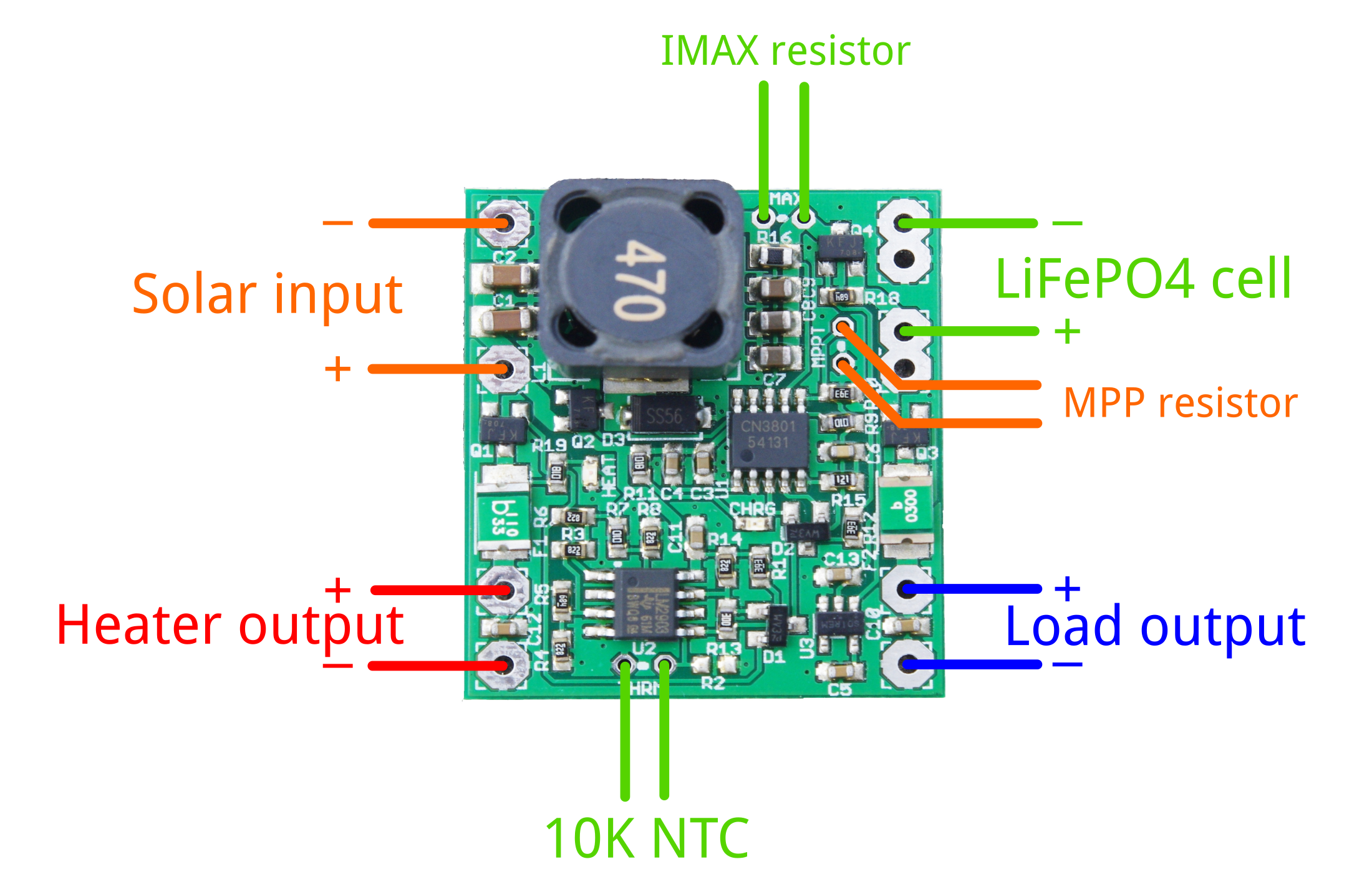
To extract the maximum amount of power from your solar panel, you need to customize the maximum power point setting to match that of your panel. Use the following formula to calculate the value of the MPPT resistor:
MPPT = 120500 / (Vmpp - 4.295)
Some examples values from my own testing with different panels:
There are many ways that charge current is limited by different parts of the system, so often it's not necessary to worry about limiting the maximum charge current. For instance, even in the brightest sun, the output power of the solar panel may be limited to the extend that the charge current never reaches the limit of the battery. You can check this by taking the wattage of the panel, and using it to calculate the theoretically maximum charge current (Icharge = Ppanel / 3V).
If you find you do need to limit the current, you can calculate the maximum current as follows:
Ichargemax = 0.12 / Rsense
Rsense for different default charge current versions I have for sale:
The maximum charge current can be increased by adding a resistor IMAX in parallel with the sense resistor already present on the PCB. The new sense resistance can be calculated by:
Rsense = Rdefaultsense * IMAX / (Rdefaultsense + IMAX)
You can then use this new Rsense value to calculate the resulting charge current limit.
A 10K NTC thermistor needs to be connected for the system to operate correctly. The system has been designed for thermistors with a B value of 3950, but reasonable performance can be had for B values down to 3435. There is a footprint for surface mount (R2) as well as through hole (THRM) thermistors. Only one of them should be used at a time.
Many battery packs come with a 10K thermistor built-in, and connecting this thermistor to the charger is the ideal situation. If no thermistor is present in the battery pack, we sell a thermistor with 8 cm leads that can be taped to the battery pack. A surface mount thermistor on R2 may work if there is little temperature difference between the PCB and the battery. If you don't want thermal protection of any kind, a 10K resistor can be installed instead of a thermistor.
Below are calculated threshold levels for different B values of the thermistor:
In under temperature conditions, the solar panel's voltage is applied to an optional heater connected to the HEATER pads. This can be used to bring the battery up to temperature before charging is started, ensuring that no low temperature lithium plating occurs and thus maximizing battery life.
In its simplest form, the heater can be a power resistor thermally connected to the battery pack. Since no MPP is maintained, the user needs to take care to choose the resistor value so it will not collapse the solar panel voltage under reasonable light conditions where enough energy is present for heating, while at the same time ensuring it doesn't pull more than 1.1A under ideal light conditions.
I received my prototype panels from Elecrow, very happy with the quality of these low cost boards I must say! So I went through the work of setting up the TinkerMill's TM245P pick-and-place machine to build prototype panels. I made a video to show part of the build process for those who are curious:
I'm building versions with different sense resistors. In principle I could produce them all with the maximum sense resistor of 0.24 ohm and then have customers add a through-hole resistor in parallel if they want a higher maximum charge current, but people don't tend to have these very low resistor values just laying around and they tend to cost more than normal resistors, so it seems to make sense to offer different values.
I will be offering 0.5A, 1.93A, 2.35A and 3.07A current limits. Note that this only configures the maximum charge current if you have a very high input source, in practice your solar panel will have a limited current output anyway and you may be able to charge a small 0.5A battery perfectly safely with a 3.07A board if your solar panel is small.
I still have to work on documentation but I hope to have these boards available in my Tindie store shortly so people can start putting these in the field. :)
I decided to use the Hackaday Prize 2017 as motivation to try and finally push this project to production! :)
I've had a unit outdoors in my #SoundBeacon project through the Colorado winter. We didn't have a very severe winter, so it wasn't a great test, but it seemed to work fine. I never saw the battery voltage go below 3.2V.
I've incorporated some changes based on what I've learned from testing the #LiFePO4wered/18650. I've gone to a bigger, higher current Schottky diode, and a newer, higher current MOSFET that I also intend to use in the #LiFePO4wered/Pi+. I hope to streamline my operations by trying to standardize components across projects. I also added a lot of thermal vias near the power components, especially the Schottky diode, to pull heat to the ground plane. With these changes, I hope that the system will be capable of 3A charge and load currents. To accommodate this, I also changed the thermal fuse on the output. The updated schematic is available in the files section.
If I did all my calculations correctly, the thermal protection system should be able to work with 10K NTC thermistors with B value between 3450 and 3950 (this seems to be some sort of "standard" in battery packs... I wish they'd ACTUALLY pick a standard resistance and B value instead). The battery will stop charging and the heater will kick in when the temperature falls below -3.1 to 0.2 degrees C. Charging will resume when the temperature rises above -2.5 to 0.7 degrees C. On the high temperature end, charging will stop when the temperature goes above 58 to 63 degrees C and will resume when the temperature falls below 52 to 57 degrees C.
I decided I need to get many more prototypes into the field to build confidence in the system. So I designed a panel so I can build a good number:
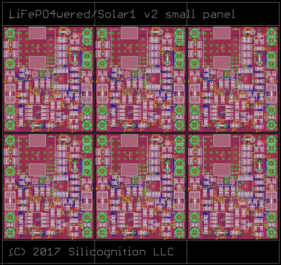
It's a small panel designed to fit within the 10x10 cm limits of Elecrow's Special Offer. So I will be getting 10 panels of 6 PCBs and I intend to use Tinkermill's TM245P pick-and-place machine to build these myself, since there are no difficult, small pitch components.
They are not officially for sale, but I had one customer very helpfully offer to buy some (at reduced "prototype" price) and test them in his devices. Thanks much Will! I want to encourage anyone else who has a need for a solar power supply to do so as well. The more field test data I can collect, the better!
I've added a PDF of the schematic! At this point, the main charging part is know to work, but not thoroughly tested over the full voltage and temperature range. The over and under temperature protection has not been tested either, nor has the heater.
But it might be useful to someone to get an idea. :)
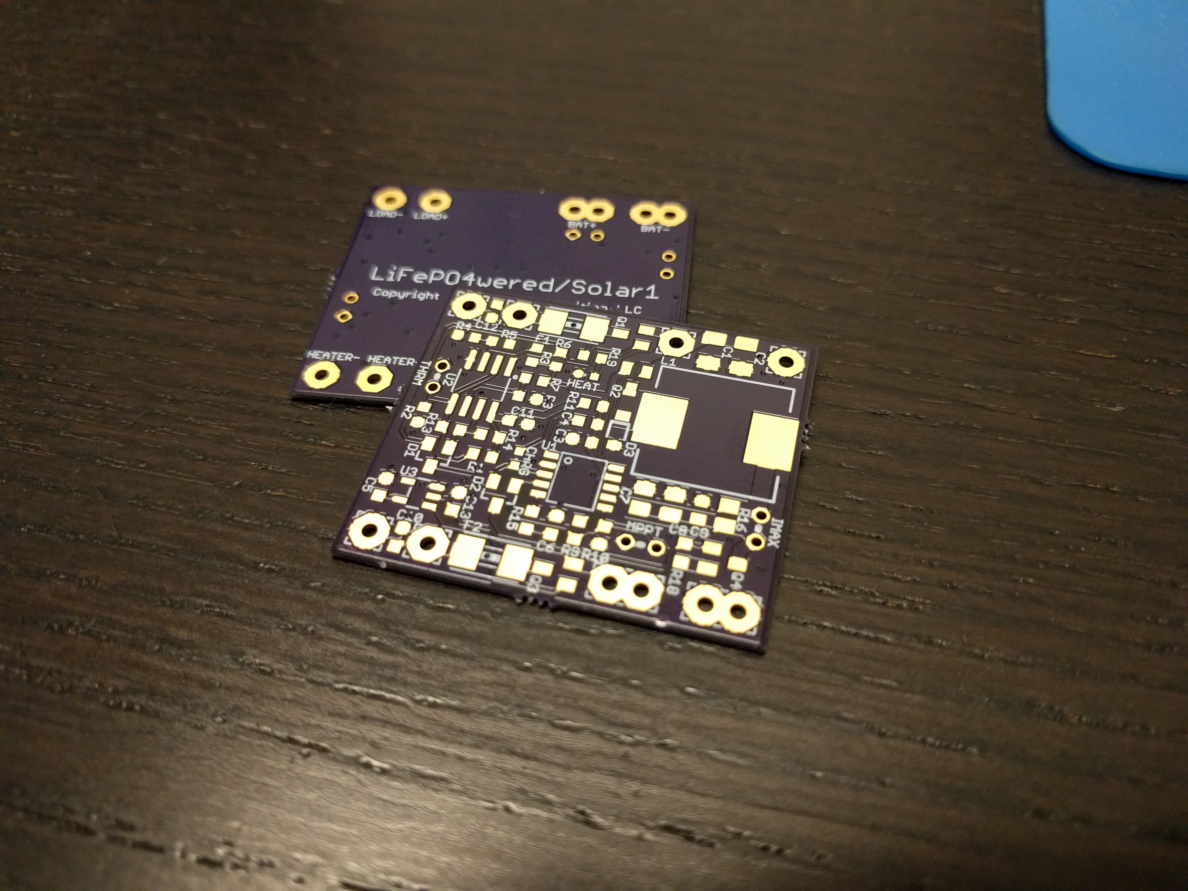
Received some perfect purple PCBs from @oshpark, so it was time to build prototypes!
I decided to build up all three boards at once (I guess I'm an optimist), and use a stencil and solder paste, but place the parts by hand instead of using the Pick-and-Place available here at the Tinkermill. I tried to use the laser cutter to make a kapton stencil. It worked horribly, but after many tries I finally had something usable enough to make these three boards. Here are the PCBs with (fairly messy) paste applied:
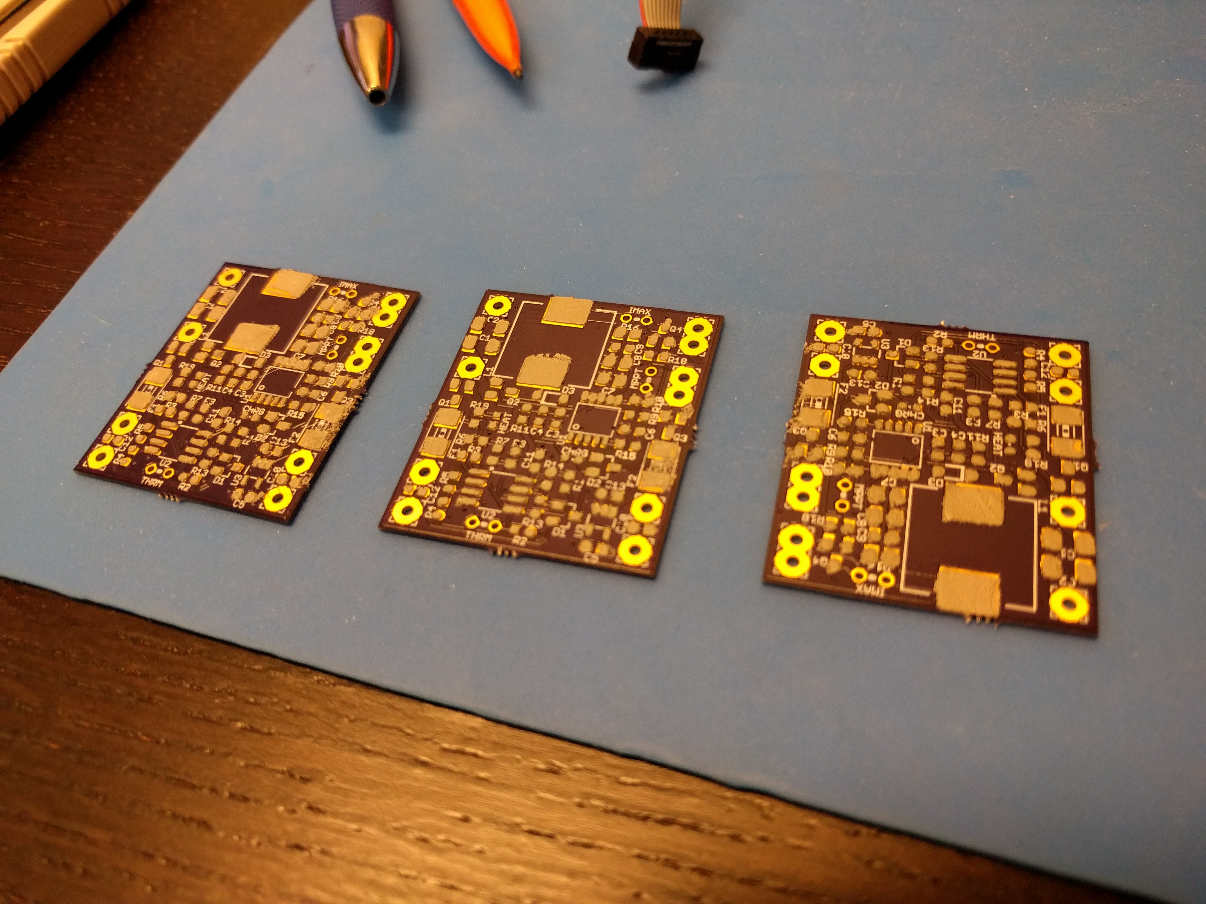
I figured the messy paste would be OK in this case since no small pitch components are involved. After spending some time placing the parts, this is how things looked:
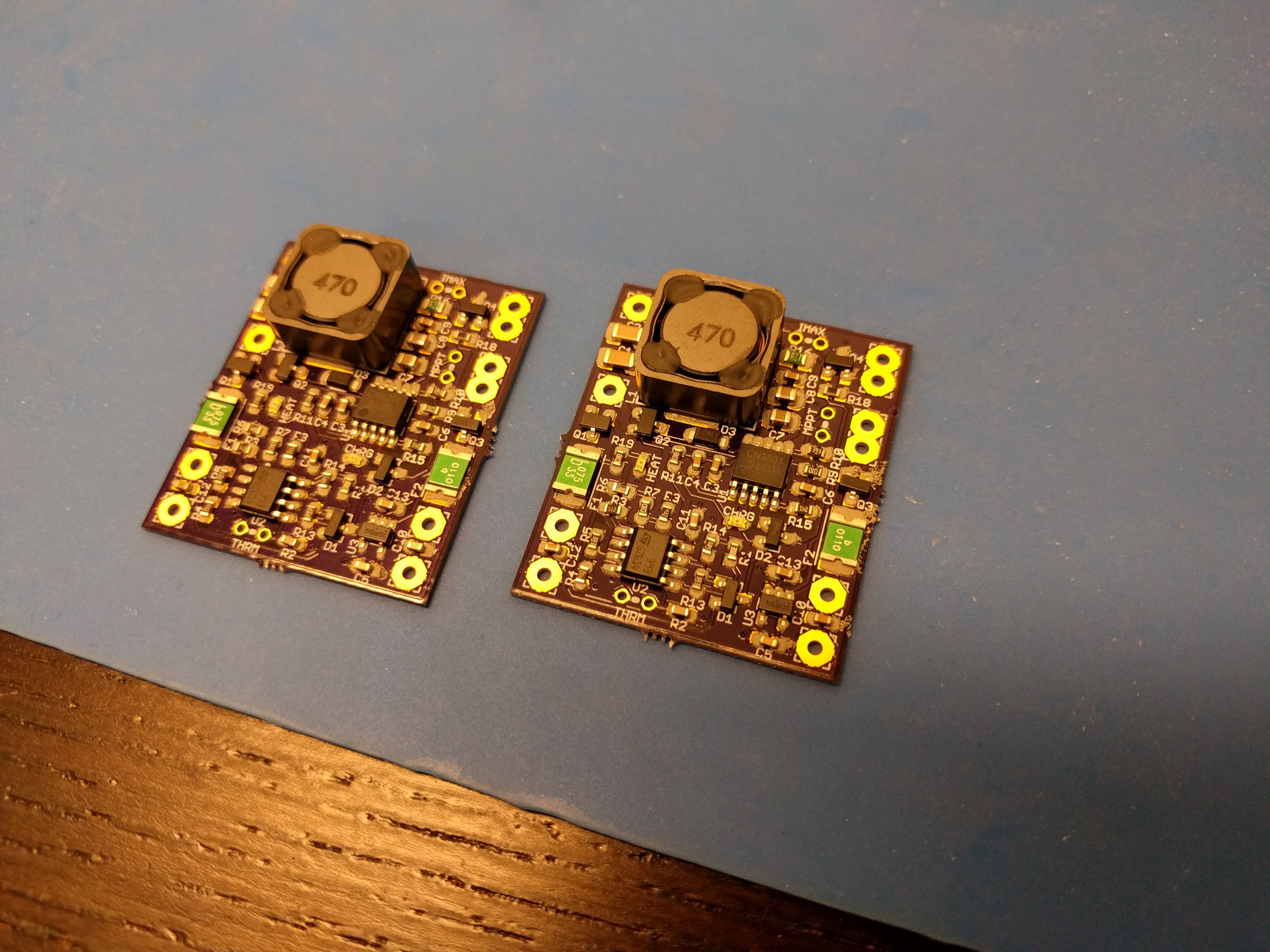
Only two boards in the picture because the other one is in the reflow oven. :) The end result after all three boards were reflowed:
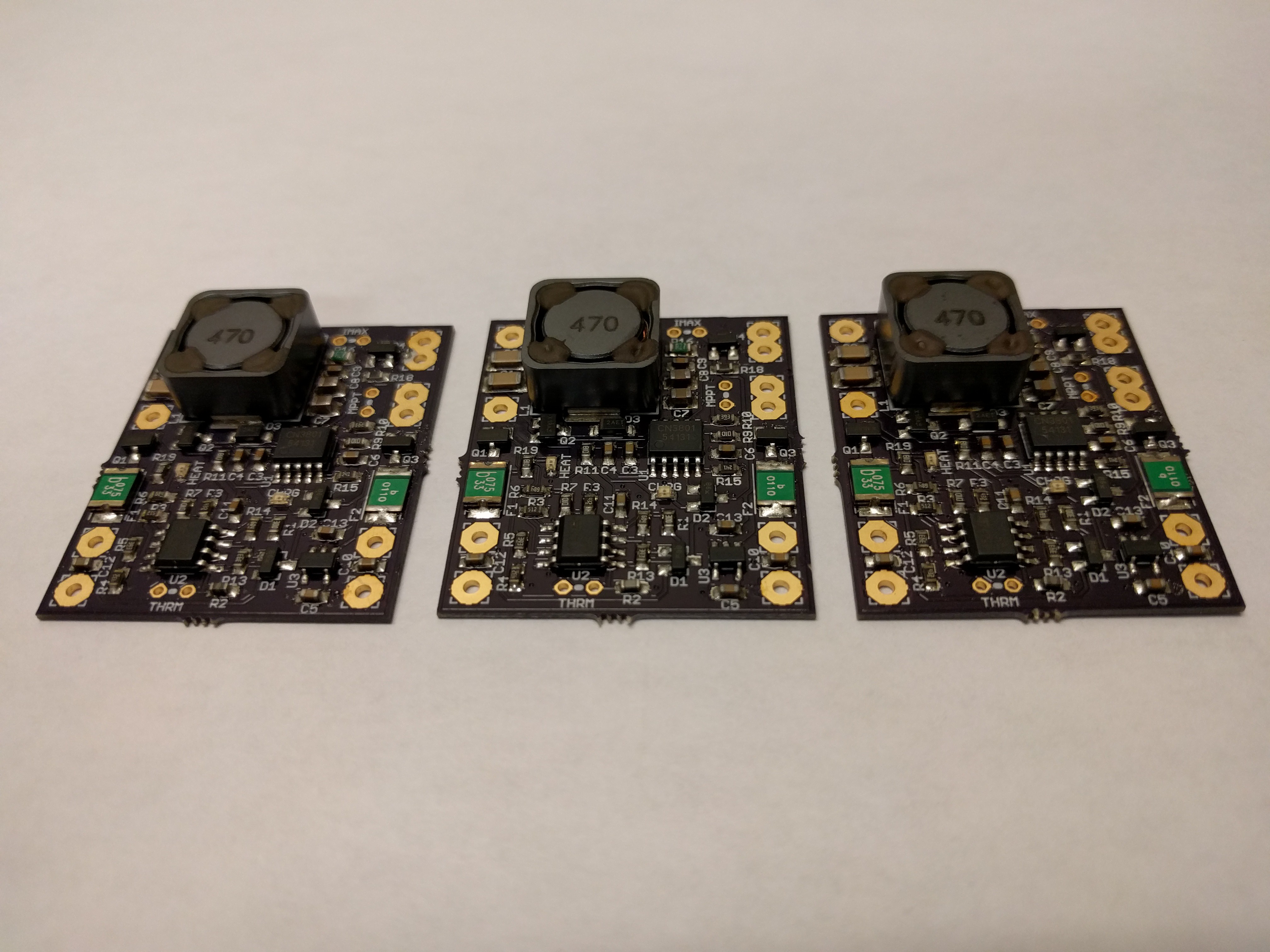
Nice, they turned out well! Next, I need to find some time for testing.
Create an account to leave a comment. Already have an account? Log In.
You could, but you'd have to be careful about back feeding either the battery or the USB/LDO. The LiFePO4wered/Solar1 output switch is a MOSFET with a body diode that could feed power back to the battery.
I would suggest that the easiest way to implement this would be to diode-OR solar and USB to the input. Of course this would only work if the MPPT voltage was not set higher than 5V...
I'm just getting started with this board and so far so good but something I'd love to see on future versions is mounting holes. Unsure how I'm going to mount this in my enclosure but the ideas so far are less than ideal.
I agree completely, thanks for the feedback!
Hi Patrick, nice board! I'm looking at using the CN3801 in a project and was wondering if you've ever had any problems or reliability issues with it? If you had to start over from scratch would you stick with it?
Hi Ryan, sorry for the late reply.
The CN3801 has been great, I have had zero problems with it and would definitely recommend it!
Is it correct you could charge with larger currents by changing SSM3J332R ?
If the current 3A limit is dependent on SSM3J332R ( ID -6A ) and not by CN3801 ( except for the RDS sense ). Meaning you could easily charge larger batteries with a "better" power mosfet M1.
With 0.039 ohm 3A => 0.35 W is lost in heat ?
A neat add on could be a MCU analyzing how much charge that goes in to the battery ( like ATtiny861 with differential gain connected to RDS )
----
I think 10Ah batteries like this could be a good target for your charger
http://shop.i-tecc.de/lifepo4-akku-wina-10ah-3-2v.html
with a waterproof box with your charger in the lid
Thank you for the links, they do look like good starting points to build a complete solar power supply!
As for increasing the current, you would indeed think that changing the power components would be a simple way to get a higher power system, but unfortunately there is a snag. I was wondering why the spec mentions 4A as maximum current, and I found out why when doing some load tests for my #LiFePO4wered/Pi+ project (which uses the same charging chip). It turns out that the Schottky diode in this asynchronous design is a major factor in limiting the maximum current. Because it ALWAYS will drop voltage, and more voltage for higher current, it dissipates power and generates a lot of heat. You can't just get a better Schottky to remove the voltage drop, it's intrinsic. It turns out that the generated heat reduces the current regulation reference voltage in the CN3801 (from 120mV to as low as 95mV), so it will draw less charge current. The whole thing is sort of self-limiting when it gets hot. Short of physically separating the power stage from the chip, | have found no solution for this.
In the future (after my vacation) I plan to write a project log for my #LiFePO4wered/Pi+ project explaining the problem in more detail.
Great project! Thinking buying one to you!
The CN3801 appears to be really good part for LiFePo4 charging and trying to find shops/sources to buy.
Where did you source that part?
Regards!
Thanks! :)
Because I do a lot of work with LiFePO4 and I also thought it was a great part, I bought a reel directly from the manufacturer. I couldn't find any distributors who carried it unfortunately.
"Input voltage range of 5V to 30V for compatibility with a wide range of solar panels."
why 5V when CN3801 can work from 4.5V ?
CN3801 - Wide Input Voltage: 4.5V to 28V
Woops, you are absolutely correct. Now I wonder where I got the 5-30V from... maybe Consonance changed the spec? Or maybe I'm just stupid. :)
Thanks for pointing this out, I've updated some references to the input range. I haven't tried it myself but I don't see any reason why it shouldn't work from 4.5V as the spec says, I don't think any of the components I've added would have a problem.
One possible concern was the common mode input range of the LM2903 in the temperature protection circuitry, which becomes a potential problem at lower supply voltages. But I just double checked that the specified behavior in the datasheet is correct even when the temperature is low enough to bring the thermistor signal out of common mode range.
Patrick, can you pease share PCB files? I will build some and join the testing with my IoT devices powered by your project!
Threw 1000w 80A hp power pack safely. I need help pm me if you dont mind.
I need something that wont melt 3d printers. I bought the mosfets but now I want to totaly build from ground up "hotbed" and not have problems.
Hi,
If you're talking about LiFePO4 batteries: yes, there are high discharge versions that handle currents like that.
This little IoT charger won't though. :)
Ive been seeing these alot lately and im wondering how they handle the high amps and temps?
As much as I dislike the tone of engineerallens comments - I think comments are for opinions. Just think he forgot all the "for me", "in my opinion" and "personally" to replace the "all people", "no one" and "everyones". You have your selling numbers and customers to prove there is someone who needs or wants it. Everyone else here knows: no tinkering and making is ever useless, as long as you learn from it.
Man he's rude.
looks nice but makes more sense to have a board specific to your solar setup
forget about range inputs and only 3.2v out
circuit should be part of the solar system
battery system should be appropriate for solar system in operation
you wouldnt stick an IoT on a giant panel or the other way around
Someone at HaD messed up and deleted the useful comment below instead of this troll comment.
But since it's here, I'll address it.
Of course an application specific circuit is going to be more optimized, whether that means size, performance or cost optimized. For instance, if the input voltage is limited to lower values, the inductor can have a significantly lower value. For lower current systems several components can be lower cost as well.
Of course the battery system needs to be appropriate for the system in operation. Did you notice I did not specify a battery size?
And "an IoT" can be anything. I use this with a little BLE board in my #SoundBeacon project, and it works very well with a tiny panel. But if you're going to make an IoT product based on a Raspberry Pi 3 instead, you will need a much bigger panel.
This project is intended to cover this "IoT" range. It may be overkill for tiny IoT projects, and won't work well for ultra low power indoor applications either, but I think it covers a useful range of applications and solar panels. In case you didn't notice, people like to build stuff out of modules, even it it just enables them to quickly prototype. By using modules, people who have a broad application knowledge, but not necessarily the detailed knowledge in electronics required to make a solar charger, can accomplish amazing things. That's what I want to enable with this.
When you make standard modules you have no choice but to cover a range of applications. For those who want an optimized solution, they can hire me to do it or they can take a look at the schematic and create an optimized system themselves. Do you really think it would be better if I just didn't share this? I sincerely hope the basic design can be useful to someone else.
I really don't get why HaD hasn't banned you yet. You just troll and have nothing to _contribute_. You realize what you say is just an opinion, right?
This project is by no means perfect but calling it "no good" is preposterous.
[this comment has been deleted]
It doesn't do perturb-and-observe MPPT, but you can set a minimum voltage setpoint with a resistor, and the charger will only draw the amount of current that will not make the solar cell voltage collapse below this point. As long as the solar cell voltage is higher, the charger will draw current up to the max charge rate, which can be set with a resistor as well.
The current will automatically flow from the charger to the load if the load needs it. This will just reduce the charge current going to the battery. If the battery is full already, the current will flow directly to the load.
A parts list would be great - I'm wondering what the large "470" part on the board is.
That's the 47uH inductor for the switching charge regulator.
I hope to put up more info soon when I have tested some basic functionality. Of course, after I built this the weather turned cloudy. *lol*
Become a member to follow this project and never miss any updates
 Patrick Van Oosterwijck
 DrYerzinia
 mr.jb
mr.jb
 andyhull
Does anything speak against implementing a load sharing circuit between the battery output and a 3.3V source (5V USB + LDO) to be able to power the load from USB also.
Great board thx for your effort ,want to use it for weather monitoring in the field.