-
1Step 1
To Build or Not to Build: The OpenLD Hardware
I have to emphasize that the design files I have provided above are prototypes. There are safety features that are not yet implemented which can be quite dangerous if misused. Therefore, I recommend that you either improve upon the above design or get an OpenBCI board as an alternative. Although the OpenBCI platform is not yet supported, it definitely will be in the future.
-
2Step 2
Building the OpenLD Hardware
There is not much to say here. I only recommend building your own OpenLD board if you have some experience with surface mount soldering. The OpenLD Fabrication Documentation will come very handy during the build, especially page 5 which shows the individual component placements on the PCB.
When you finish soldering the components, it is important to bridge (short out by placing a blob of solder) the S4 jumper that is located on the bottom side of the PCB. This jumper connects the chip select pin of the ADS1299 to the STM32F4 microcontroller.
I advise you to buy male 1.27mm male headers (not 2.54mm headers!) in order to connect wires to the headers present on the OpenLD board. These small headers are an absolute pain to work with, but their small form factor is definitely advantageous over the traditional 2.54mm headers.
-
3Step 3
Programming the STM32F4
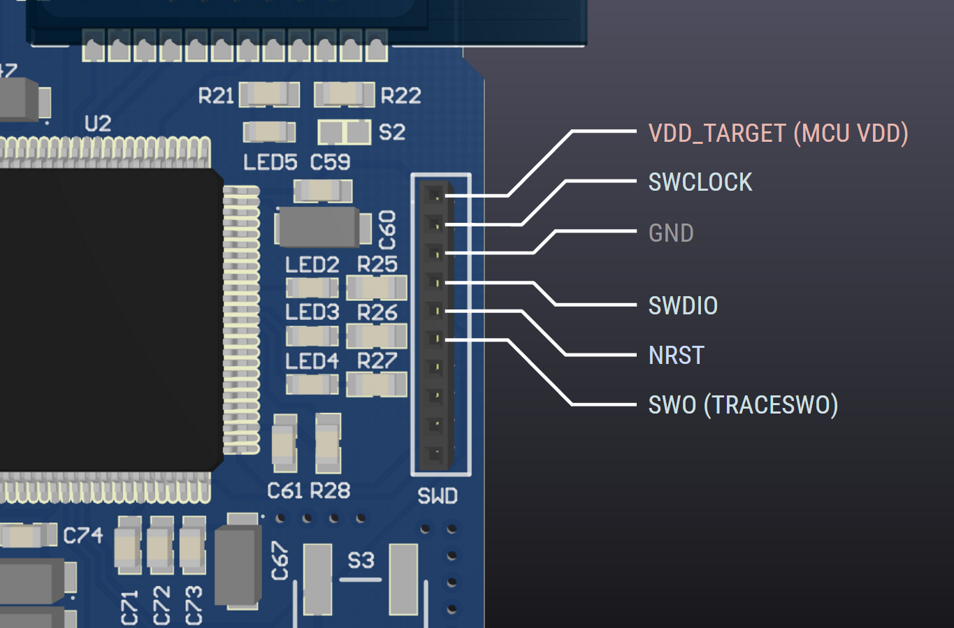
You can either use the STM32Discovery/Nucleo boards or a dedicated STLink V2 programmer to burn the firmware to the OpenLD board. Just make the necessary connections between the SWD connector on the OpenLD board to the programmer. Refer to the schematics in the OpenLD Fabrication Documentation and the below diagrams to figure out which connections go where:
OpenLD SWD Pinout
![]()
STM32Discovery SWD Pinout (User Manual - Page 15). Make sure to remove CN3 Jumpers! Also, ST-Link V2 SWD Pinout (User Manual - Page 12)
-
4Step 4
Building the OpenLD Firmware
You can either build the project from source or download the binary file from the Github repository. If you just want to burn the pre-built binary to the OpenLD board, skip to Step 3.
Step 1: Building the Toolchain
Download the toolchain for the GNU ARM cross-compiler and add the /bin directory to the $PATH variable. Make sure that you can successfully run arm-none-eabi-* commands from the terminal.
Step 2: Building and Burning the OpenLD Firmware
In a directory, git clone the OpenLD repository and download the STM32F4 Standard Peripheral Library. Make sure that the two directories (OpenLD-Hardware and STM32F4xx_DSP_StdPeriph_Lib_V*) are located in the same directory. Afterwards, you can enter the OpenLD-Hardware directory and run make.
$ cd .
$ git clone https://github.com/Absolute0K/OpenLD-Hardware.git
$ unzip en.stm32f4_dsp_stdperiph_lib.zip
$ cd OpenLD-Hardware
$ make
Step 3: Burning the Executable
Download and install the ST-Link utility:
Windows: Grab the ST-Link utility from the ST website and install the program. Follow instructions in the section 3.5 Device Programming in page 21 of the User Manual to burn the OpenLD binary file.
Linux/Mac OS X: Install Texane st-link command line utility from the Github repository (or use package manager - read the README.md file). Run the following command to flash main.bin file. (If you have built the program from scratch, you can run make install to flash the board. It is equivalent of running the command below.)
$ st-flash write 0x08000000 bin/main.binNote: the pre-built binaries can be found on the OpenLD-Hardware repository, under the "bin" directory.
-
5Step 5
Setting up the Bluetooth Module
Before reading the instructions, please check out this great video tutorial by Kevin Darrah (all credits go to him). You should watch the entire video, as it is very informative, but if you are impatient, start watching from 14:35. (He explains the process for both OS X and Windows).
Please refer to the RN42 Datasheet (Especially page 7 which shows LED status indicators) and the Bluetooth Command Reference Manual (Page 24 and 26)
Note: In the video, he uses the built-in Arduino IDE terminal. But I also had success with other terminals, including Blueterm on Android.
Follow the video tutorial, and when you enter the RN42's remote configuration through the Terminal (after entering $$$), type in the following commands:
SN,"OpenLD"
SU,23
The first command sets the name of the RN42 Bluetooth name to "OpenLD". Feel free to change this name to whatever you want.The second command sets the baud-rate of the RN42 from 115200 bps to 230400 bps. This is required for the STM32F4 to talk to the RN42 correctly.
Those are the required changes. Exit by typing "---".
IMPORTANT: When you want to acquire data from the OpenLD, always wait until the RN42 is in data mode (LED blinks slowly) before starting a connection. If you connect while the LED is blinking fast (control mode), the data-rate is going to be severely limited, causing huge amount of packet-losses.
-
6Step 6
The OpenLD Software
This Qt C++ software require a few dependencies: the FFTW3 and nCurses library. Therefore, if you want to compile the Qt Project, make sure to copy the include files and the libraries to the project directory. If you do not want to build the project yourself, I will release pre-built executables for Windows, Linux, and OS X in the future. More documentation on the software will be included as the software is developed
-
7Step 7
Inducing Lucid Dreams
The primary method I used to induce Lucid dreams was to simply wake up from the OpenLD alarm. The OpenLD plays a soundtrack whenever REM stage is detected, therefore by waking up at that stage, I can use various induction techniques. Check out Laberge's Exploring the World of Lucid Dreaming for more information. (There is an online PDF available, but I recommend supporting his work by purchasing the book)
OpenLD: Lucid Dreaming Research Platform
An open source platform to help induce and explore the realm of Lucid Dreaming for Research and Personal Well-being


Discussions
Become a Hackaday.io Member
Create an account to leave a comment. Already have an account? Log In.