-
The Software: Principle of Operation
09/21/2016 at 16:34 • 0 commentsWith the hardware build complete, along with its firmware, it is time to begin creating the crucial part of this project: the brainwave analysis software. This program will analyze the EEG brainwaves received from the OpenLD hardware by Bluetooth and trigger specific cues to help the induction of Lucid Dreams. Let me explain the basic background and overview of the OpenLD Software:
Sleep Stages and their Characteristics
You might have heard a thing or two about something called sleep stages. Before the 1950's, sleep was assumed to be a period when the brain became inactive and passive. It was only after scientists discovered through EEG recordings that the brain went through different phases of activity (sleep stages) during the entire duration of sleep. These stages are comprised of Stage 1, 2, 3, and REM. They occur in the order described below, with each cycle being approximately 90 minutes long: (APA, "What is Sleep?")
- Stage 1: This stage takes place right after falling asleep, often known as light sleep.
- Stage 2: At this stage, the brainwaves start to slow down ...
- Stage 3: Here, slow delta waves begin. This stage is called deep sleep.
- Stage REM: This is when dreams occur. The brainwaves at this stage are very similar to waking state.
![]()
The diagram above shows a generalized depiction of how sleep cycles through these different stages. Note, these cycles are different for everyone and varies overtime.
Image Source: http://www.centerforsoundsleep.com/sleep-disorders/stages-of-sleep/In this project, the REM stage is the phase that we are most interested in, as dreaming takes place here. It is important to note that at this stage, the Rapid Eye Movements actually reflect the eye movements of your dream. That means that if you look upwards in a dream, your physical eyes will do the same. Since the rest of the body's muscles are paralyzed during REM, which prevents the body from acting out the dream, these eye movements will be an important part of the OpenLD in-dream communication.
The OpenLD Software Overview
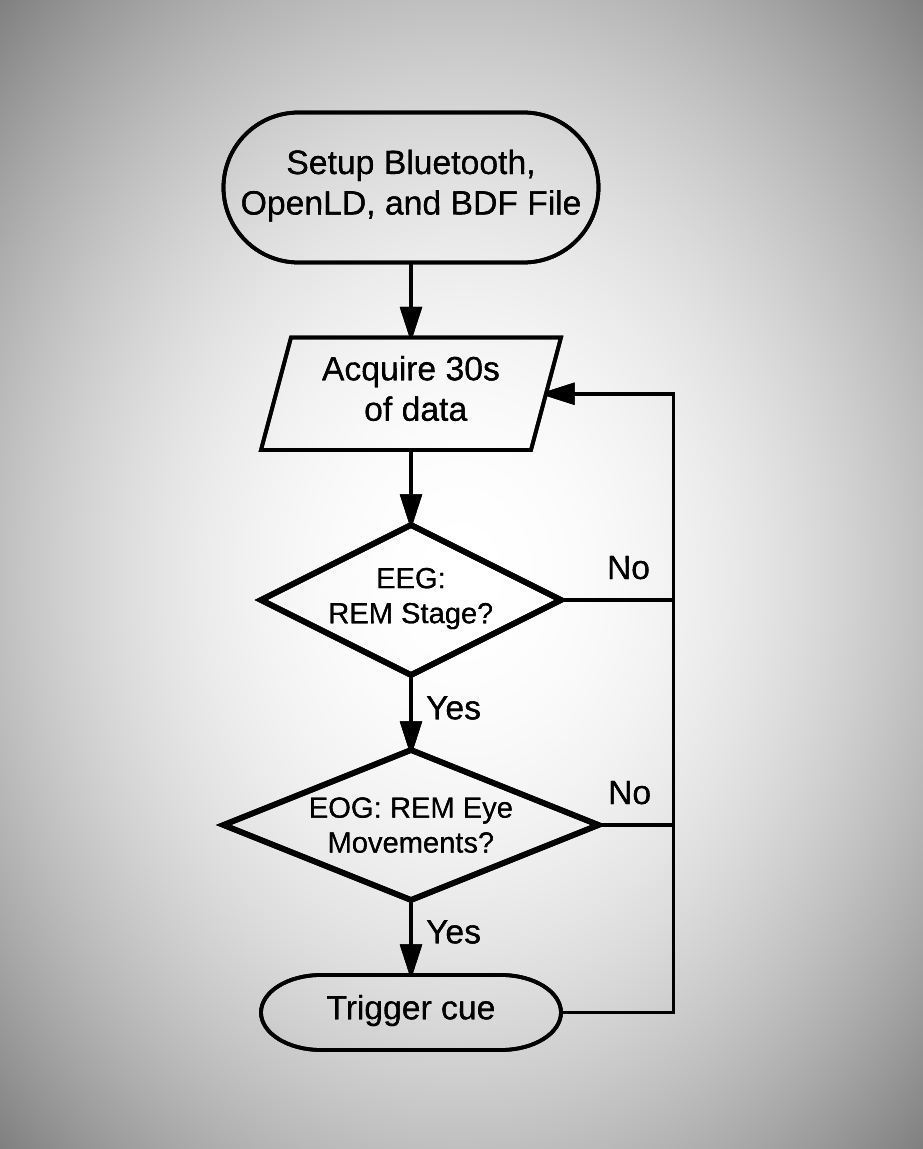
Overall, the OpenLD helps to induce Lucid Dreams by triggering a specified cue (such as a specific soundtrack) when it detects that he/she is dreaming. The difficulty lies in determining whether or not the person is dreaming. In the OpenLD software, this is determined by a 2-step verification process, as described in the flowchart below:
![]() The software will first set up the appropriate hardware and files. After connecting to the OpenLD hardware through Bluetooth, the program will create a BDF file, which is a biosignal file format specified by BIOSEMI inc. This file can be opened by a great program EDFBrowser by Teuniz.
The software will first set up the appropriate hardware and files. After connecting to the OpenLD hardware through Bluetooth, the program will create a BDF file, which is a biosignal file format specified by BIOSEMI inc. This file can be opened by a great program EDFBrowser by Teuniz.
After setup, the program begins the analysis process. When 30 seconds of data has been collected, the software analyzes the data to detect if the subject is dreaming. If the data is confirmed by the two verification steps (described below) the subject is deemed to be dreaming and a Lucid Dream cue is triggered.
- EEG: REM Stage - This step uses a single EEG electrode, located at the site Fp1-A2 in the 10-20 system, to determine if the subject is in an REM state. The software will make this decision using an algorithm published by Imtiaz et al. More details about this procedure will be included in future project logs.
- EOG: REM Eye Movements - This step uses two EOG electrodes to detect if any rapid eye movements have been made. If the algorithm detects the eye movements, the current stage is flagged as being a dreaming state. A cue is then triggered in order to induce Lucid Dreams.
That is the general overview of the OpenLD software. In the future project logs I will be delving into the mathematics and the implementation of the mentioned algorithms. I will publish the alpha-but-working version of the software in Github in the near future.
Sources:
What is Sleep? (2007, May). Retrieved September 21, 2016, from https://www.sleepassociation.org/patients-general-public/what-is-sleep/
Imtiaz, Syed Anas, and Esther Rodriguez-Villegas. "A low computational cost algorithm for rem sleep detection using single channel EEG." Annals of biomedical engineering 42.11 (2014): 2344-2359.
-
Performance Evaluation of the OpenLD
09/15/2016 at 17:29 • 0 commentsRoot Mean Squared (RMS) Noise of OpenLD
Here is the plot of the noise recorded by the OpenLD hardware. In order to measure this noise, the electrodes were all shorted out by connecting the positive channel inputs to SRB1 and the BIAS pin. For the ADS1299 configuration, the PGA gain is set to 24 and 4 channels were powered on.
![]()
The datasheet indicates that the RMS Error (equivalent to the standard deviation) of the signals (at 24x gain and 250SPS) are approximately 0.14uV (pg. 7; Table 4). If you look at the diagram above, the RMS values of the signals recorded by the OpenLD is also around 0.14uV. Brilliant.
-
Firmware for OpenLD: STM32F4 w/ ADS1299
09/12/2016 at 19:07 • 0 commentsI apologize for the lack of build logs. I will be uploading them more frequently, as I have progressed significantly in terms of firmware & software for this project.
Github repo for the (beta) version of the OpenLD firmware here!
Apologies of the rogue assembly codes in the firmware. The readability of the entire firmware will be improved in the future, I promise.
General Overview of the Firmware
![]()
In the STM32F4, we need to enable the required peripherals in order to use them. Therefore, the program starts out by enabling GPIO, SPI (for ADS1299), UART (for the Bluetooth module), and Interrupts. Also, it sets up the configuration registers for ADS1299, which is described below. The program then goes into an infinite loop and relies on interrupts for the rest.
The firmware has 3 concurrent interrupts. The interrupt EXTI9_5_IRQHandler, which is activated by the ADS1299 DRDY signal (pg. 8-9), reads data 250 samples per second from the ADS1299. This data is saved in a buffer.
Meanwhile, interrupt EXTI0_IRQHandler is triggered when 250 samples are received in the buffer, hence every second, and sends it to the RN42 through UART for Bluetooth transfer. Since the update rate is not a huge issue, I have opted for 1-second packet transfers for simplicity.
There is also another interrupt for SETTINGS() option, which presents a command line-like interface that is used for enabling & configuring channels. This interrupt is triggered by sending a 'S' character.
ADS1299 EEG IC from Texas Instruments
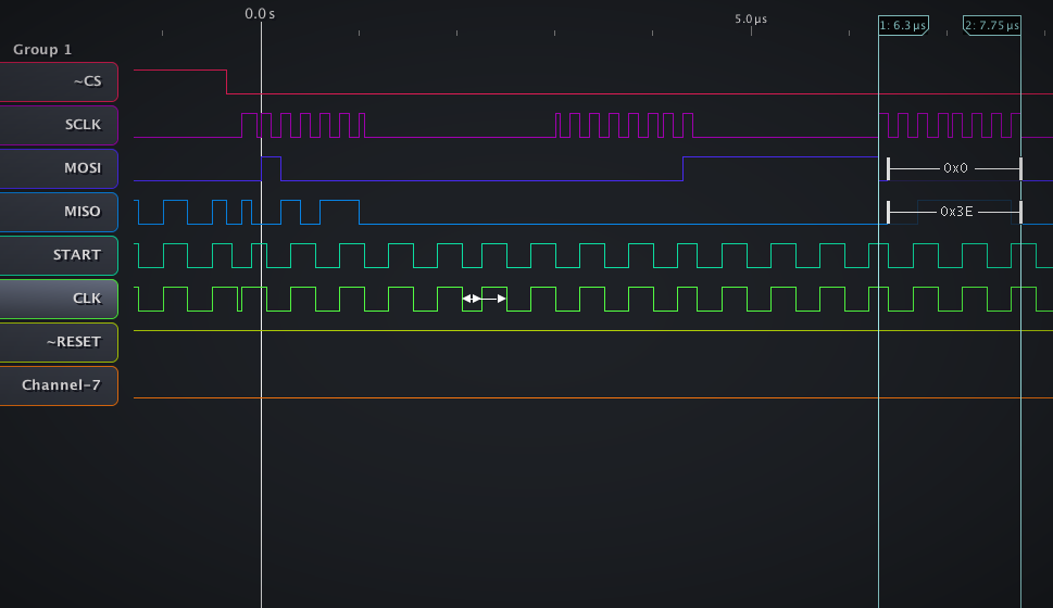
![Title]()
WHOAMI signal from ADS1299 (ID Control Register), captured from the SPI bus with a logic analyzer
The ADS1299 is an all-in-one chip for EEG data acquisition, which makes the hardware much simpler (no need to worry about amplifiers and DRL!). After reading through the 65 page long datasheet, I came to the following conclusion for the configuration (I highly recommend going through the datasheet yourself, as it is fairly involved):- Data sampling rate of 250 samples per second: Since sampling rate for sleep brainwave analysis is not critical, the ADS1299 rate was set to its default, the minimum value. This also helps to conserve data bandwidth for the Bluetooth connection.
- PGA gain of 24: According to the datasheet (pg. 7), highest signal to noise ratio can be achieved by setting the PGA (Programmable Gain Amplifier) to the highest (24x) gain. Although this means higher power consumption, the lower noise floor improves the quality of the EEG data.
- Bias Electrode: Also traditionally known as DRL (Driven Right Leg), it is a source that inverts the average signal of all 8 channels and drives it back to the body. It significantly helps to improve CMRR of the EEG amplifiers.
- Reference Electrode: EEG recordings are differential, hence they need 2 electrodes to obtain a signal. The input SRB1 is used in the ADS1299, which allows the negative input of all 8 amplifiers to be connected to a single electrode. Refer to pg. 17 for more information.
In the Github repo above, the function ads1299_init() in the file cmd_ADS1299.c initializes the features described above.
I apologize for this rough explanation. This is just a beginning of the software side of OpenLD. Now, things are going to get much more interesting. Next time, we'll be evaluating the performance of the OpenLD.
-
The Hardware: Finishing the EEG Device Build
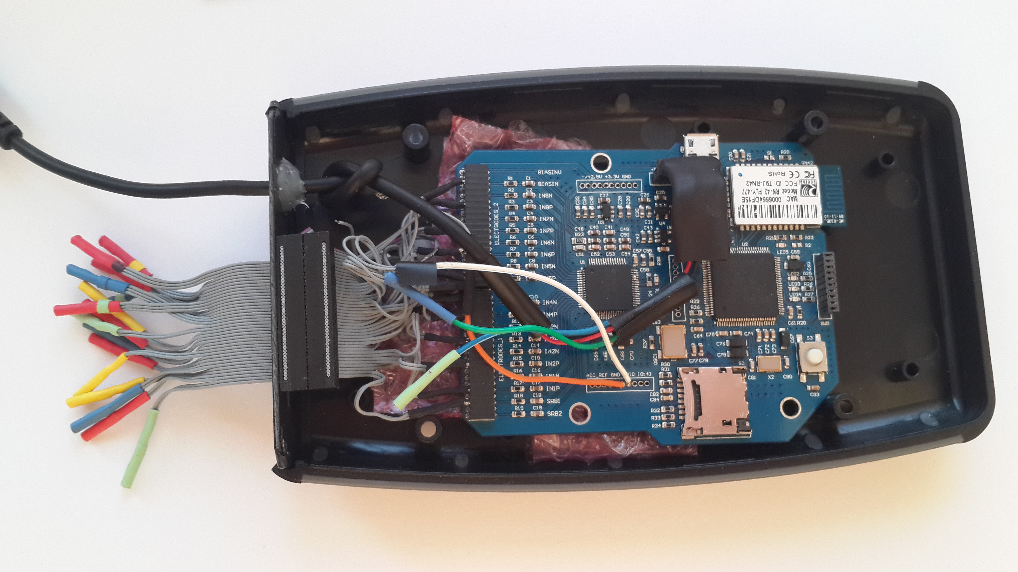
08/30/2016 at 16:32 • 0 commentsHere is the finished prototype with an enclosure
![]()
The device in operation with a USB portable power supply
![]()
The electrodes will be connected to the female connectors located on the left side of the EEG device. Since this hardware uses a Bluetooth connection, it is fully portable. This also helps with the safety of this design, as it has absolutely no electrical connection to the 110V/220V mains for power.
In the future, a custom 3D printable case will be designed. But for now, I will focus on getting this platform up and running, as the software side of this project is where the real challenge lies.
This pretty much concludes the 1st revision hardware build for this project. It is now time to write some code for obtaining and processing the EEG data. In the next post, I will post the code for the ARM processor and measure the performance of this EEG Acquisition device.
-
The Hardware: EEG Data Acquisition device with an ARM Processor
08/26/2016 at 17:39 • 0 commentsEEG Hardware Description
![]()
Electroencephalogram (EEG) is a procedure that measures the electrical activity within the brain.
In this project, a custom built EEG device (CAD screenshot above) will record and analyze brainwaves, which will be used to induce/research lucid dreams.
Component Selection for the EEG Hardware
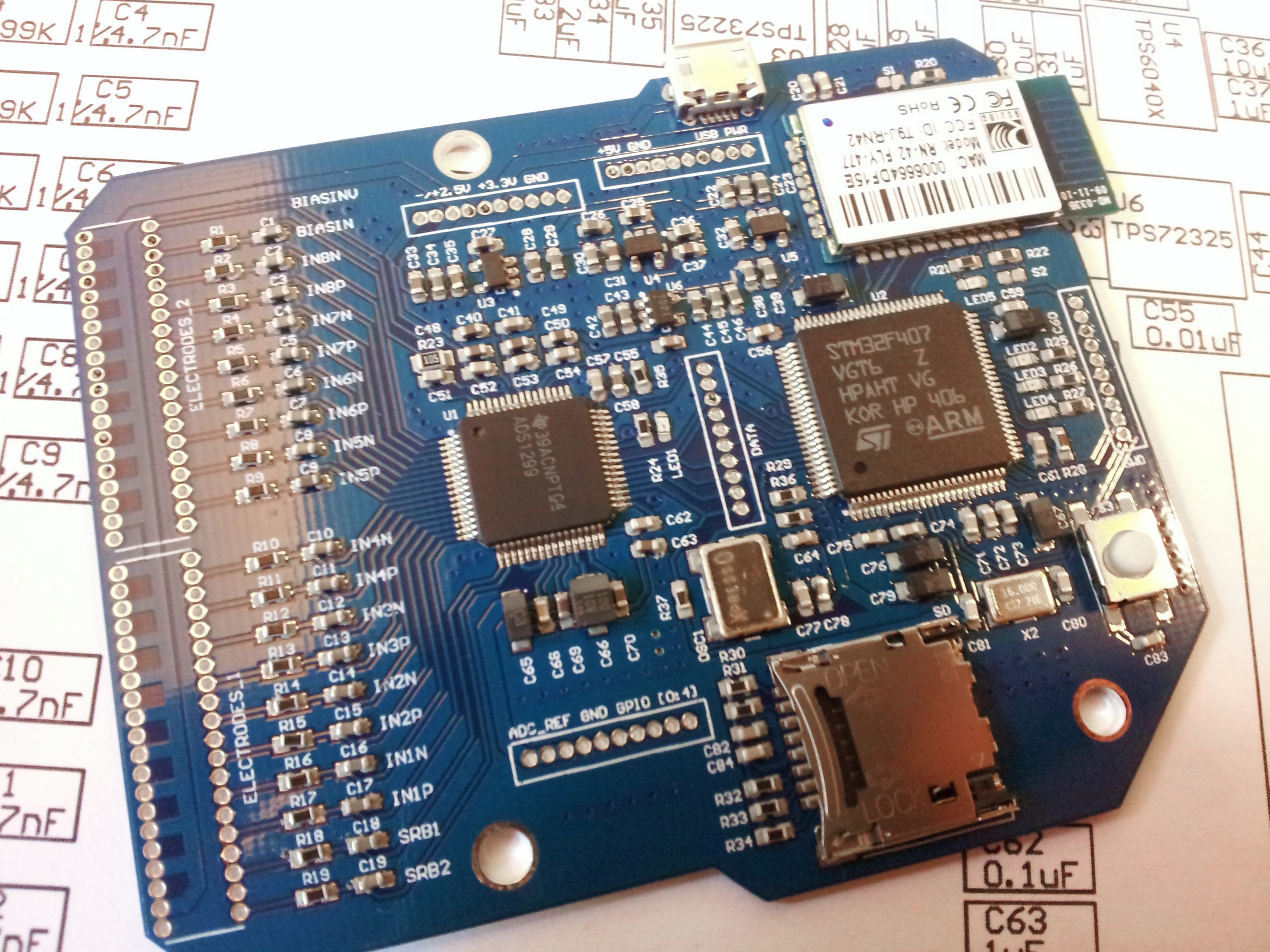
This board contains an ADS1299 chip from Texas Instruments, which is an analog front-end IC containing 8 EEG amplifiers and delta-sigma ADC's. Thanks to this IC, this tool can record 8 channels of high resolution 24 bit EEG signals at a sampling rate of 250 samples per second. This chip is accompanied by a powerful ARM Cortex-M4F microcontroller (STM32F407VG) which handles the data from the ADS1299.
To transmit the data to the PC, an RN42 transceiver module is used to send the EEG signals via a Bluetooth connection. This allows the device to be used wirelessly, which makes it portable and easy to handle. This will be especially important as the mess of electrode leads will be a pain to manage during an EEG session.
Note: The device USB port should NEVER be connected to a main power supply. This can potentially be lethal and, under no circumstances, should it be ever attempted.
Project Files for the EEG Hardware PCB
![]()
Schematics of the OpenLD - ADS1299 Data Acquisition stage
The Schematic and the PCB design files (gerber files included) are located in the Files section of this project page. Unfortunately, as of right now, the project files are in an Altum Designer format. However, this format will be changed to other more open source friendly CAD software (Circuit Maker, KiCAD) for later revisions of this board.
Now time for the build
EEG Hardware Build Process
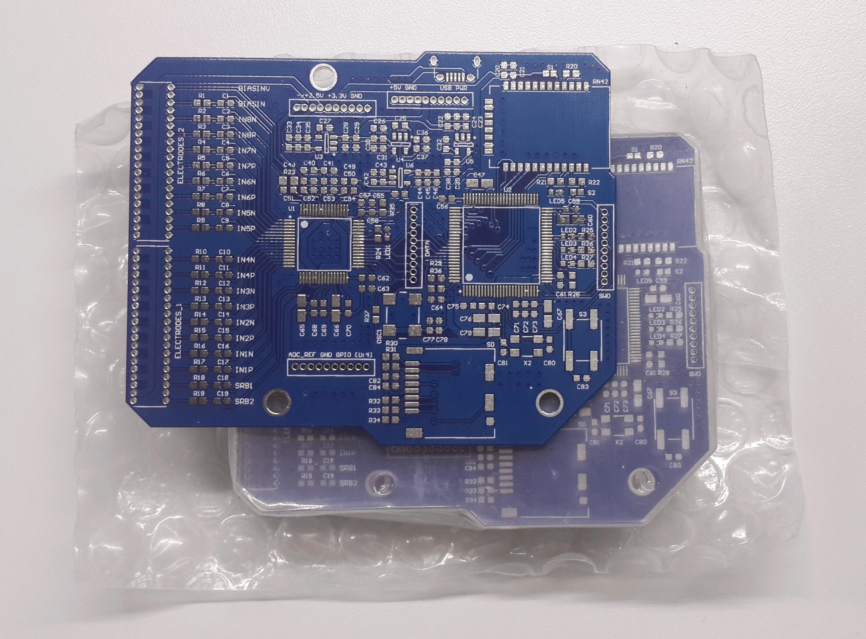
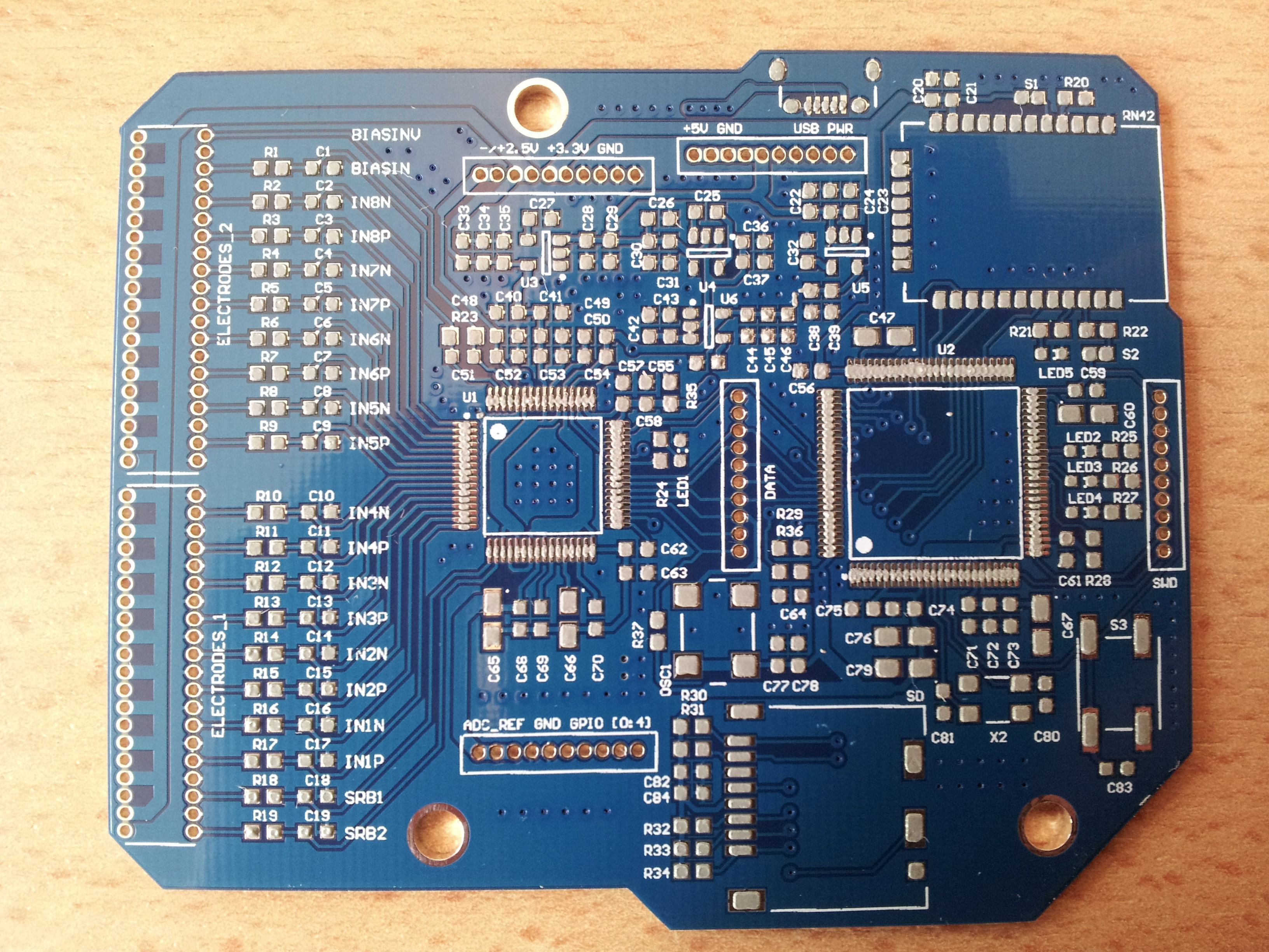
The manufactured PCB's
![]()
Applying Solder Paste
![]()
![]() Random note: The solder stencil used above is made out of disposable aluminum pan. It is much easier to make (but more fragile) than the well known method of using soda can aluminum.
Random note: The solder stencil used above is made out of disposable aluminum pan. It is much easier to make (but more fragile) than the well known method of using soda can aluminum.
Components placed, and now ready to be cooked in the oven:
![]()
There it is. The board is done.
In the next update, I will be adding an enclosure and soldering appropriate connectors for the EEG board. This will more or less cover the main hardware side of this project.
OpenLD: Lucid Dreaming Research Platform
An open source platform to help induce and explore the realm of Lucid Dreaming for Research and Personal Well-being

 The software will first set up the appropriate hardware and files. After connecting to the OpenLD hardware through Bluetooth, the program will create a BDF file, which is a
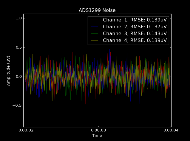


 Random note: The solder stencil used above is made out of