Alvaro Ferrán Cifuentes
-
OpenChair v0.1
09/17/2016 at 18:48 • 0 commentsThe first version we tried was the one seen in the render below, simply attaching a couple of brackets to the hoverboard and two more to the chair and connecting them with a tube with two bolts as fasteners to keep everything in place.
![]()
We really liked this idea because it was simple (KISS): the user would only need to unscrew the lid, connect the wires to the corresponding buses and bring them out of the case by removing one of the front lights, all while keeping the original structure and with minimal work.
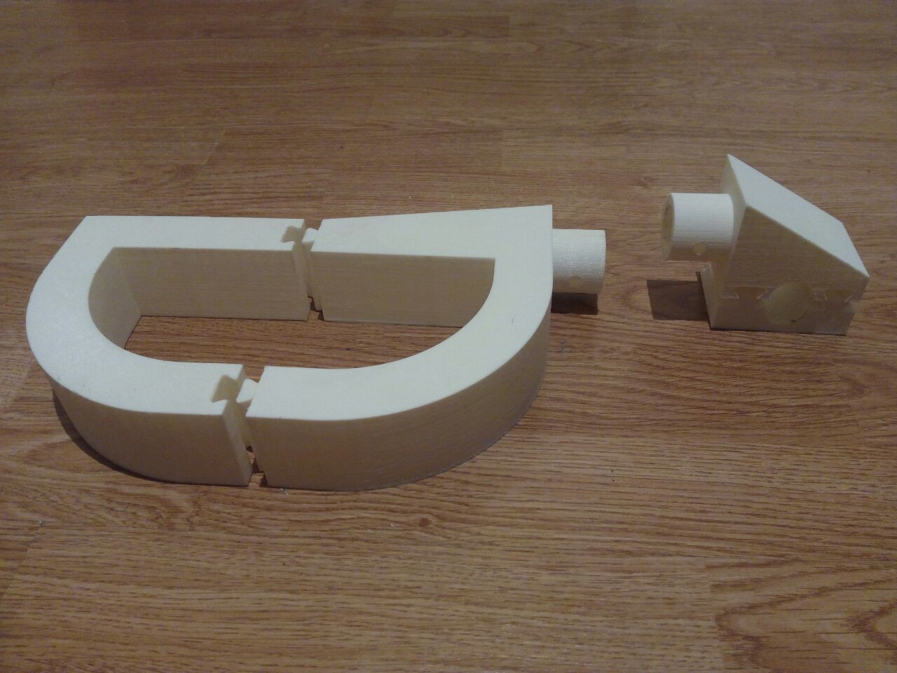
In the picture below we can see the brackets of both the hoverboard (left) and wheelchair (right). Notice all the pieces are designed with rails for ease of (dis)assembly while retaining strength by orientation.
![]()
Under this design, the chair would still theoretically be able to turn on its spot, since the distance between the board's wheels was larger than than the one between a chair-wheel and a board-wheel. However, once we started designing everything we realized a problem: while the board's width is larger, the tubes needed to be connected to the chair to its inner side, which in turn means that now the distance between the tubes was quite smaller than the one between the board and the chair, and there was no way it would turn on its axis, which is essential for indoors maneuvering.
Other problems are that the now larger chair may not fit in dedicated wheelchair spaces reserved for regular chairs or that having a 10kg device at a distance of half a meter would put a substantial amount of stress on the printed joints, and moving on a bumpy street would only worsen that.
With all of these problems we decided that this design would not be viable and went back to the drawing board.
-
Understanding the hoverboard II
09/17/2016 at 18:08 • 2 commentsIn the previous log we saw how to control a single wheel over UART. The natural progression is to simply plug in the second wheel and do the same thing to have complete control over the board and be able to spin the wheels at our hearts' content.
Wrong. We can spin each wheel independently as long as the other one is stopped, or move both in the same direction (making the board turn on its axis), however trying to make the board move (above a minimum speed!) along a straight line results in the wheels accelerating until they achieve the maximum allowed speed and are turned off by the beeping controller board.
While this may at first not make much sense, it actually is a very intelligent control method:
-When going at low speeds the user is able to navigate obstacles by having full control of the board and the wheels behave just as expected.
-However, going above a certain speed will trigger the "cruise mode" in which we trade fine control for a large range of speeds. In this mode the inclination controls the board's acceleration instead of its velocity, meaning that if while moving forwards the user stays in the same inclination, the board will start speeding until the users move to a vertical position, at which time the acceleration will be zero and the board will remain at the selected cruise speed. Then to decelerate it is simply a matter of turning the board slightly backwards until the it reaches either a lower cruise speed, stops completely, or starts moving in the opposite direction.
With all this in mind we have found that the way to control the board is:
-When moving at slow speeds or rotating, continue as usual.
-When moving in cruise mode first send the desired speed to the wheels and in the next iteration send a zero value, to maintain the board's velocity constant. Then to stop the board, either keep decelerating until the speed is zero, or send an emergency stop signal (simulating a fallen user) by making the sixth byte of the command a '0x000' instead of the '0x055' normally sent.
-
Understanding the hoverboard
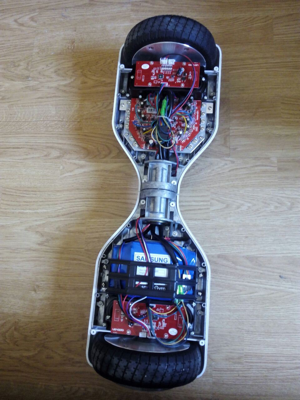
08/31/2016 at 22:08 • 1 commentFirst things first, disassembly time! In the picture below we can see the different components making up the hoverboard. We can see two gyro boards, one main board and the battery.
Each gyro board contains a Cortex-M3 processor calculating its orientation from an MPU-6050 accelerometer/gyro sensor and sending it over UART to the main board, which is responsible for both driving the motors and charging the battery.![]()
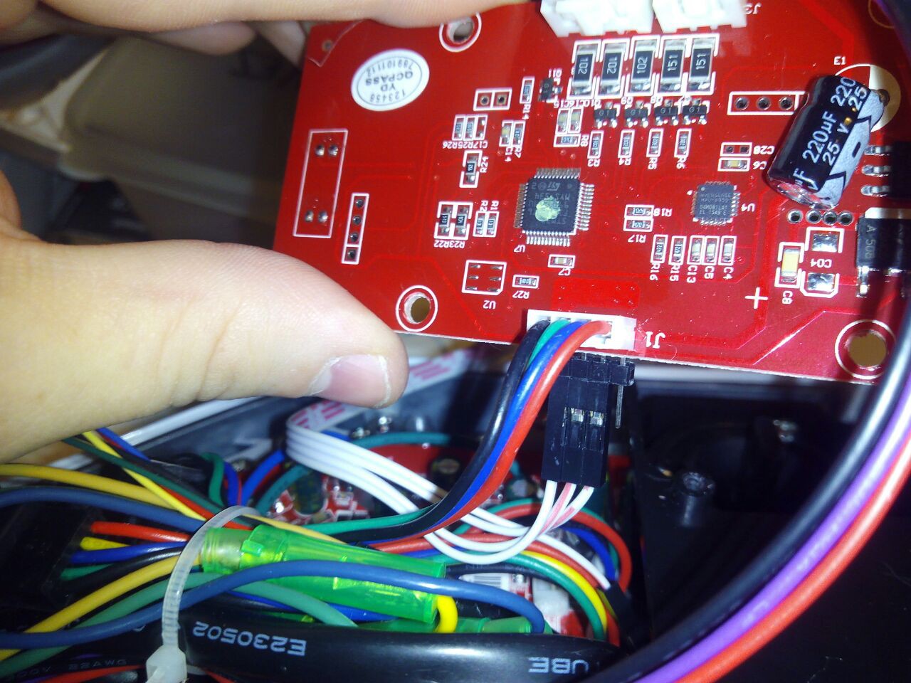
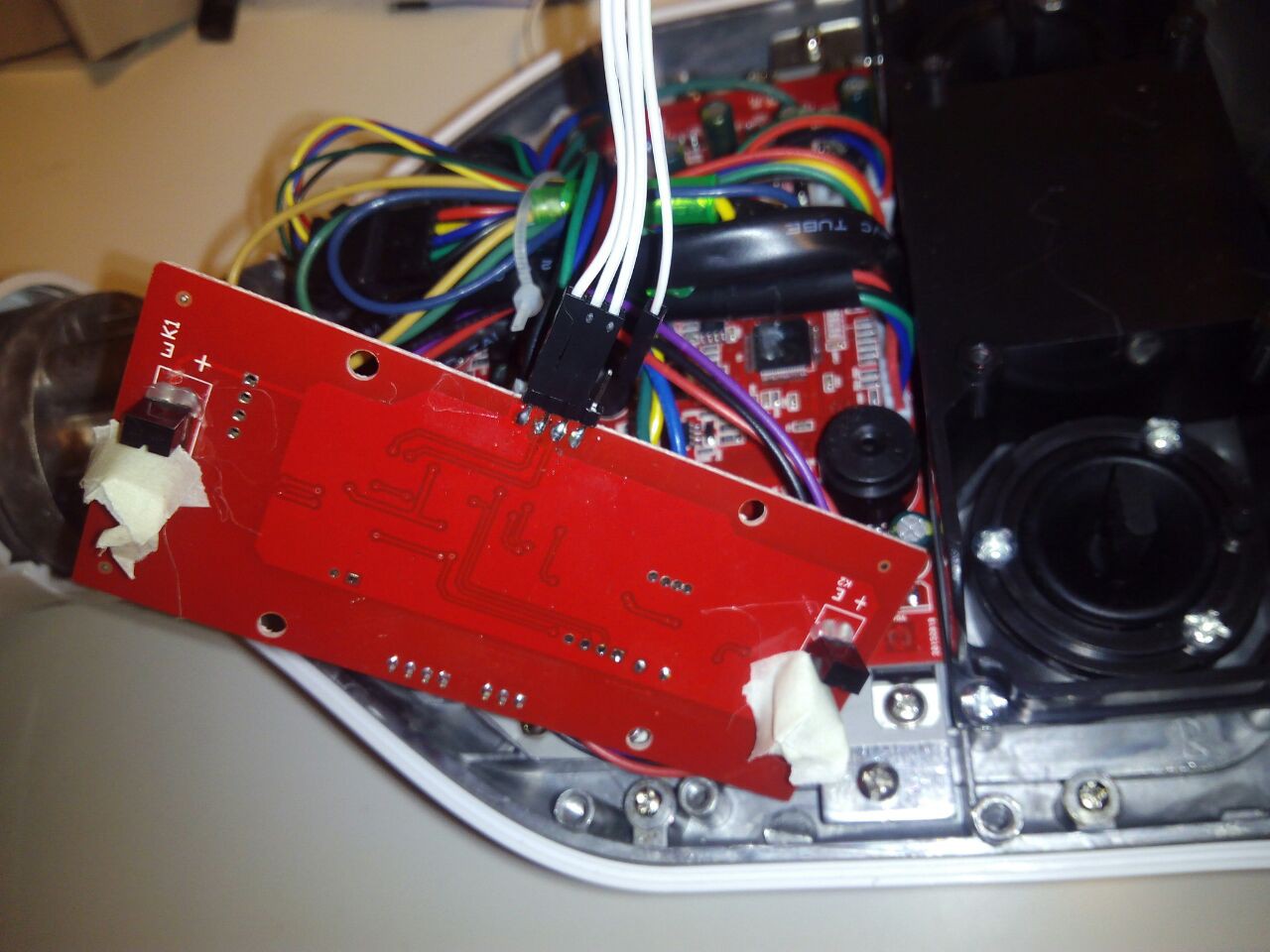
Thanks to Drew Dibble's work we know that the UART lines run at 26315baud, with 1 stop bit, no parity and LSB-first. In the pictures below we see the serial bus and the IR sensors used to check if the user is standing on the board, which we will spoof with a bit of tape.
![]()
![]()
Using a logic analyzer we find, as Drew explained, that the instructions follow a pattern of six commands: 0x100, 0x0aa, 0x0bb, 0x0aa, 0x0bb, 0x055. The first command marks the start of the instruction, and the last is 0x055 if both IR sensors are blocked.
We captured data at various inclination angles in both directions to find out the values of the middle bytes. The table below shows the data being sent by the board when increasing the angle. For example, if the board is tilted a few degrees forwards, it sends the sequence 0x100, 0x053, 0x000, 0x053, 0x000, 0x055, which can be seen as 0053h or 83d.
Forwards (hex) Forwards (dec) Backwards (hex) Backwards (dec) 0x053
0x00083 0x0C0
0x0FF65472 0x06C
0x000108 0x08C
0x0FF65420 0x013
0x001275 0x065
0x0FE65125 0x0A8
0x002680 0x061
0x0FD64865 0x07E
0x0051408 0x04C
0x0FB64332 0x069
0x00F3945 0x030
0x0F863536 0x07B
0x0165755 0x0F0
0x0E057584 As we can see, when moving forwards the values go from 0 to over 5k, while going backwards the values would go from 65535 to about 57k.
Armed with this knowledge, we can easily map the input of a potentiometer to the range of speed desired, and control the motor from our favorite dev board!