-
1Step 1
Pressure pads needed to be an appropriate size to make pressure easy, while being able to be placed close enough together for complex movements such as moving the mouse diagonally. After tracing my foot, I came up with pad sizes of 4"x2.5" for the Left/Right/Down pads, and 6"x2.5" for the Up (toe) pad. This allows for pivoting on the heel to press Up/Left or Up/Right at the same time. The Velostat pads are reduced by 1 - 1.5" to allow for dead zone and room to sew.
Using a rotary cutter, cut 12 4"x2.5" pieces of neoprene fabric, 4 6"x2.5" pieces of neoprene fabric, 6 2.5"x 1.5" pieces of Velostat, and 2 4.5"x1.5" pieces of Velostat.
-
2Step 2
Measure out and mark a square in the center of each piece of neoprene for the placement of the Velostat pad. Inside of this square, sew a zig-zag pattern with conductive thread to ensure strong contact and consistent results no matter where the foot contacts the pad.
Then place the Velostat between the two pieces of neoprene and sew the edges of the Velostat in place. Movement of this layer could cause a short, or inconsistent results when pressure is applied.
Attach 12"-18" wire tails, I used 24ga solid-core wire, which I had laying around, to allow for easy connection to the PS2 cord.
Finally, sew the perimeter of the neoprene pad, ensuring to put in some strain relief for the tails. The solder joints between the conductive thread and the solid-core wire are likely to be weak.
-
3Step 3
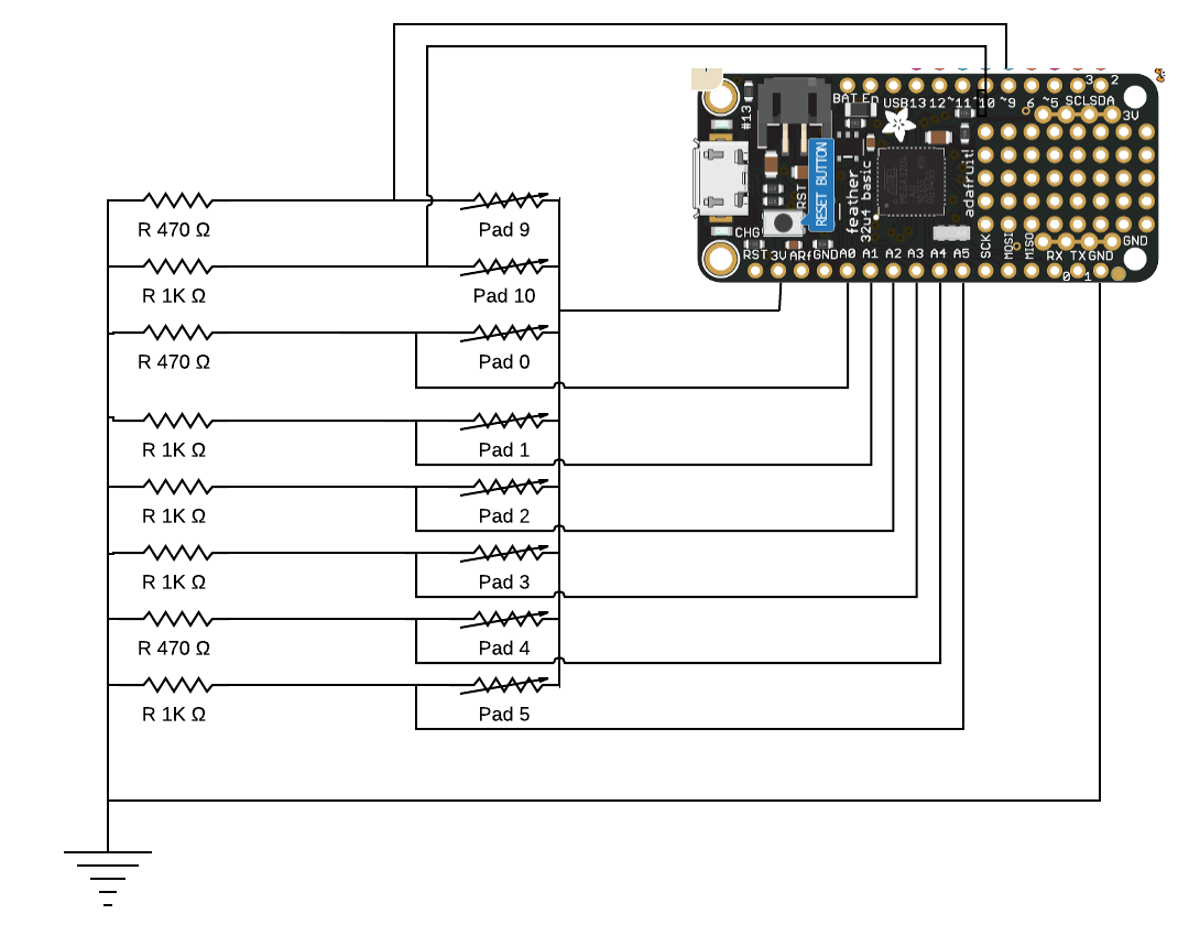
Test each pad individually, to try and get reasonably similar resistance patterns. Typically I saw resting resistance at 4K ohm, with pressure reducing to resistance 400 ohm. One pad had less base resistance, so a 560 ohm resistor was added to the wire tail to balance it out. The toe pads also had a lower resistance, and required a smaller resistor in the voltage divider to balance.
The schematic below shows the usage of 1K ohm and 470 ohm resistors in the voltage dividers to achieve a signal between 300-900 (on the Arduino measuring scale of 0 to 1023). You may need to make changes depending on the outputs from your pads.
-
4Step 4
Cut the 6-foot PS/2 Cable in half, and trim to desired length. The PS/2 connectors provide a strong, keyed connection to the controller box, and each wire carries 6 conductors (of which we need 5).
Tie one conductor from each pad together for the 3v rail. Tie each of the remaining wires to a unique conductor on the PS2 connector. When complete, you will have 2 sets of 4 pads (one toe, and 3 L/R/D).
Note that the colors in the PS/2 wire may not match the colors on the PS/2 female connector, so some continuity testing to map your specific components may be required.
-
5Step 5
The schematic for the control board is pretty simple. In this build, I used basic radio shack perfboard, which does not have vias or support soldering. This meant wrapping component tails through the board and soldering directly to them.
The schematic below shows the use of 470 and 1K ohm resistors to create voltage dividers. I used the calculator at https://learn.sparkfun.com/tutorials/voltage-dividers to aim for a resting voltage of about 1.3v.
![]()
The perf board was cut to 4.825"x1.5" in size to fit within the project enclosure. This enclosure was selected because it had enough internal volume to allow the use of the USB-B panel mount connector. Because this will be on the floor and likely to be kicked, I felt the use of the larger, panel-mounted USB-B connection would offer longer life than a USB Micro. This also removes strain from the connector on the Feather board and allows a modular construction. Should a component break, it will be quite easy to isolate and replace.
-
6Step 6
The microcontroller code was based off of the JoystickMouseControl demo provided in the Arduino library. This code provided a simple base for scaling an analog measurement into a value that can be used by the computer, that was built upon to support Left click, Right click, Double click, and a modifier to use the Up / Down pads to control the scroll wheel. Code is attached to this project, and uploaded using the Arduino IDE.
-
7Step 7
Finally, the pads should be mounted to a piece of MDF board using contact cement to provide structure and additional strain relief for the wiring. This allows the mouse to be used on soft surfaces as well as reduces the setup time (pad alignment with feet, etc. Cover the surface with an additional layer of neoprene fabric for wear resistance.
$50 Foot Controlled Mouse
Reimagining expensive commercial accessibility solutions with new prototyping materials
Discussions
Become a Hackaday.io Member
Create an account to leave a comment. Already have an account? Log In.