 Ivan
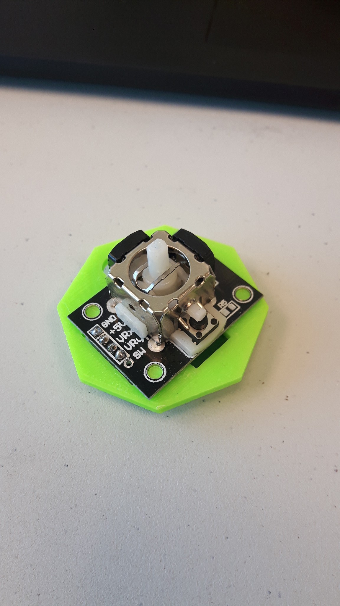
IvanAs some of you may or may not know we are using a "PS2" thumb joystick as our transducer for manipulating the cursor on the end-user's mobile device or computer. This joystick has its pros and its cons...
- pros: readily available and extremely cost effective (read: cheap)
- cons: high output voltage sensitivity due to the lack of precision in a ~1/4 turn 10k pot
The argument can be made that there are industrial-grade joysticks available but they cost upwards of $200 while the thumb joystick we are attempting to use costs upwards of $5.
So given that we are trying to keep the total cost to a minimum for when makers and disabled persons are building these we are sticking with this joystick - for now.
The high sensitivity of the X and Y axis output voltages with regard to angular deflection of the center post has been nagging at me for some time. With an input voltage of 5.0V and the angular range of motion for the center post is approximately 75 degrees and using a 10-bit ADC with a reference voltage of 5.0V looks like 5.0V / 1024 div = 4.9mV / div. The joystick original has an input voltage of 5.0V therefore 5.0V / 75 degrees = 66mV / degree. Using a voltage divider in parallel of the joystick potentiometers I reduced the input voltage to 1.25V which then translates to 1.25V / 75 degrees = 16.7mV / degree. Using the 10-bit ADC this results in 3.3 div / degree versus the original 13.5 div / degree.
This is effectively reducing the sensitivity by increasing the resolution of the joystick wherein the input (angular deflection of center post) produces a smaller differential output (millivolts per degree deflection) than the original joystick setup. This modification to the characteristics of the joystick are a good thing because it will allow for increased usability.
Experience it for yourself. Try turning your mouse sensitivity (aka acceleration) way up then let me know how effective it is when you are using your computer or mobile device. The end-user for us will be using their mouth and neck within limited ranges of motion to manipulate the joystick, so gradual cursor movement, I believe, is the way to go.
If anyone has any recommendations or feedback I would love to hear them. I'm not an electrical engineer so any help is welcome!
-Ivan
Discussions
Become a Hackaday.io Member
Create an account to leave a comment. Already have an account? Log In.
Hey @K.C. Lee so getting back to your post. We did our best to figure out which microcontrollers would best suit this application. That being said there were some criteria that we needed: availability, HID capabilities, price, ease of use and length of life cycle. These criteria are important because we want to enable makers and disabled person to build these wherever they might reside (mostly NA for now). The Arduino Micro / Genuino Micro are readily available through Digikey et al for a reasonable price, the chipset is the ATMega 32u4 which has HID capabilities, the microcontroller board has the pins pre-soldered for easy installation and from what we can gather from the relative availability of the board the microcontroller board is not near its end of life. For all these reasons and a few more, we ended up with the Arduino Micro - which happens to have 10-bit ADCs.
As for the resolution, a 10-bit ADC can differentiate voltages changes as low as 4.9mV which is no where close to what we are outputting from these joysticks. I did a single sweep signal trace of a full deflection of the joystick (I wanted to post the waveform but don't have a thumb drive handy) and I looked at the changes in voltage. I was reading stepped outputs of approximately 80mV for just a fast single deflection of the joystick. For all intents and purposes the time trace for the deflection looks linear. That being said my observations suggest that the output voltage is maxed out outside a fairly small angular range. So my proposition was to use a voltage divider circuit in conjunction with the joystick circuit to reduce the useful output range of the joystick wherein IF the output voltages are linearly proportional to the angular deflection then by reducing the useful voltage range I hope to increase the useful response from the ADC.
Now I am exploring a different cursor movement algorithm to work more appropriately with the new ADC outputs. The HID functions, the HID mouse in particular, take input parameters which are integers and represent absolute movement of the cursor in their respective axes. I believe the integer values correspond to mickeys - as far as I can determine. So a typical algorithm response would like:
@Ted Yapo how do you add images to replies?
Basically, it is a stepped response from the algorithm which computes the input parameter for HID mouse functions for both Arduino and Bluetooth.
From my testing, when the voltage divider circuit is combined with the joystick circuit, while observing the ADC output on the serial monitor I could see there was greater differentiation of digital values as well as a more responsive cursor movement with the smaller voltage range compared to the larger 5.0V range . This was without a new algorithm in place which wont affect the ADC response but the actual cursor response. I was experimenting with some non-linear algorithms yesterday but haven't landed on the most appropriate one for our purposes as well as what should be scaled to enable the user to change the cursor speed but more appropriately put it might be regarded as the joystick sensitivity. This @Ted Yapo is where your comments on the algorithm design will start to come in handy - thanks again. A quick note about your graphs, it may be in one of your edits but what I am aiming for in greater sensitivity near the home position and less sensitivity at the extremes.
@K.C. Lee I myself am still doing some hand waving convincing to myself that my proposed solution will work but I am just trying to explain my rationale within the constraints of our project parameters. The critical point of what your comment was meant to accomplish my have gone over my head - "Nothing goes over my head. My reflexes are too fast. I will catch it." - Drax
Thanks again you guys.
Are you sure? yes | no
Just paste a link to the image you want to put inline. You can host the images wherever (I think), but I have a private project on hackaday.io for testing stuff, so I just upload the image to the files section of that project to host them here - no external dependencies. It turns out, you can see files in my private project if I give you the link - it sounds like a bug, and if they ever fix it, my comment images disappear. I'm sure there's a better way.
Greater sensitivity near the center? Sounds backwards to me, but you know more about what you are doing. Once you get the image pasting thing down, paste in a schematic of your voltage-divider / joystick circuit - I'm still not sure what you're doing with that - something doesn't add up for me.
Anyway, if you want more sensitivity in the center, you can use a power less than one in a similar formula - I made it easy before and used an odd integral power so the signs work out easily, but with a little work, any powers work fine. Try:
y = 0.5 + sign(t - 0.5) * abs(t - 0.5) ^ b
with "b" between 0 and 1 (try 1/2)
you can also blend between this function and the linear one like before.
Are you sure? yes | no
Thanks for the image info, I will have to come back to that.
The more sensitive near the center (exponent < 1.0) may be useful for quadriplegics with a limited range of motion, such that they can utilize nearly the full speed range but in an even more narrow range of digital values. That being said, the joystick would probably be experiencing fine movements with varying degrees of control (lip/neck muscles). Conversely, users with a greater range of motion can manipulate the joystick more where the full range of digital values would be acceptable (exponent ~ 1.0). On the other extreme, possible users whom experience spastic movements might benefit from lower sensitivity near the center (exponent > 1.0). This case isn't totally related to ROM but usability for a wide range of users.
Right now my movement formula normalizes the input value (from joystick through ADC) then I (just started working on exponential fnc) exponentiate the normalized value and multiply that result by an imposed maximum cursor speed. Originally, I was not using an exponent and just multiplying by a scaling factor to control the cursor speed.
Hopefully this makes sense and gives you an idea behind my madness...
Are you sure? yes | no
One trick I use is to upload the picture to a new project log. Once I reference the URL of that picture in a comment, I can even cancel that project log. That picture seems to stay because of the reference. Not sure if the picture get removed eventually or the server treats it as content.
Are you sure? yes | no
I understand your reasoning now; having a fully adjustable sensitivity curve makes sense.
Here are some other sigmoid-type functions from wikipedia:
The article has some other info on similar functions which may also be suitable. I don't know if it really makes a difference as long as you have the general shape:
https://en.wikipedia.org/wiki/Sigmoid_function
Are you sure? yes | no
Hey @Ted Yapo thanks for the comment and the images, ridiculously helpful! Yeah I was literally about to start messing around with changing my cursor movement function because right now it is a linear function and our team had discussed trying to implement an exponential function. The example equation you posted above is an awesome starting point, thank you! I have been working on the hardware of the electronics for the past while but am now shifting more into the software. Thanks again for the comment like I told @K.C. Lee every bit of feedback helps because like I said I'm not an elec or comp engineer. Thanks again @Ted Yapo
Are you sure? yes | no
Thanks so much for the feedback! @K.C. Lee there are some explicit limitations on the hardware we are using and the real estate we have to work with. I am designing these so that makers, wherever they are can make them fairly easily. I would have to look into external ADCs but this might be easy for some engineers and makers but very difficult for others. However I will be looking into the ratiometric conversion, creating a more appropriate cursor movement function might be more fruitful than my hardware mod. I am reading your posts on the fly but I will hopefully post a more detailed comment by the end of the day. Thanks again every piece of feedback helps, like I said I'm not an elec or comp engineer... mech :D
Are you sure? yes | no
I agree with K.C. - software is probably the way to go here. If you go that route, you might consider a non-linear scaling of the joystick position, too - easy in software. You can make the stick less sensitive near the center position, and more sensitive at the edges - roughly giving you the equivalent of an "acceleration" parameter (yes, I know it's not really acceleration).
Anyway, you can experiment with non-linear sensitivity scalings, but here's a simple one:
x' = xc + 4*(x-xc)^3
where xc is the center position (511 with a 10-bit ADC).
This is just the first function that came to mind; it has a very low sensitivity in the center, proably too low, with most of the sensitivity at the edges. I'll see if I can come up with a better one - or find one someone else has already used - I'm sure someone has done this before. Ideally, you'd have a parameter that tunes the sensitivity.
EDIT: you can linearly blend between this and the linear function to control the sensitivity:
x' = a * (xc + 4 * (x - xc) ^ 3) + (1 - a) * x
then you choose a between 0 (linear sensitivity) and 1 (the extreme above):
EDIT AGAIN: You can also do this in hardware by adding a pair of lower-valued resistors across your joystick. I've done this for purely analog circuits, but if you have a micro available, it's probably best.
Are you sure? yes | no
You can use piecewise linear interpolation to produce any continuous functions. It is just a lookup table to interpolate the input value to output. The piecewise fit would also allow you to linearize those cheap joysticks.
I played with $10 gamepad vs my old xbox controller. The cheap joysticks gamepad makes it harder to position precisely as they are highly non-linear and this is with visual feedback and incremental position feedback. (Absolute positioning is going to be hell on those.)
The acceleration is by looking at the rate of change of the input and adjust the incremental position of the output. If the joystick is moving slowly, then you know you want to increase the output resolution (ironically by decreasing the sensitivity) and vise versa.
Are you sure? yes | no
Why would you restrict yourself to10-bit ADC? Figure out how many bits you need BEFORE choosing the ADC or microcontroller.
Even if you can't deal with anything but Arduinos, there are ARM based Arduinos with built-in 12-bit ADC. There are external ADC with much higher resolution 12-bit all the way to 24-bit. Pretty sure that you can get libraries for that and a lot of hand holding.
Why reduce the output and drop your resolution? Feed the joystick with the same voltage rail as the ADC reference to get maximum resolution. Also google "ratiometric conversion". If you need to drop the resolution, do it inside the firmware. If you ever need to change the resolution, you would have to modify the circuits.
There are also software ways to increase your resolution - look at the old mouse dynamic resolution. Or instead of absolute angle, use incremental positioning like what a joystick or a mouse would in a game. Those cheap joystick aren't exactly linear you know.
Are you sure? yes | no