leumasyerrp
-
Rev A is OK
09/08/2018 at 13:33 • 0 commentsAfter a comment by @K.C. Lee on the last project log I looked into digital/prebiased transistors and was able to find a PNP transistor (PDTA123ET,215 from Nexperia) that is a drop in replacement for the original PNP transistor. I no longer need external pullup resistors on the PNP transistors! Thanks for your comment.
Now that I have built enough of them for my desk at home and work I will post the rest for sale on Tindie. As always check out the GitHub repository for updated design files if you wish to build your own.
![]()
-
Build complete but a Rev B will be required
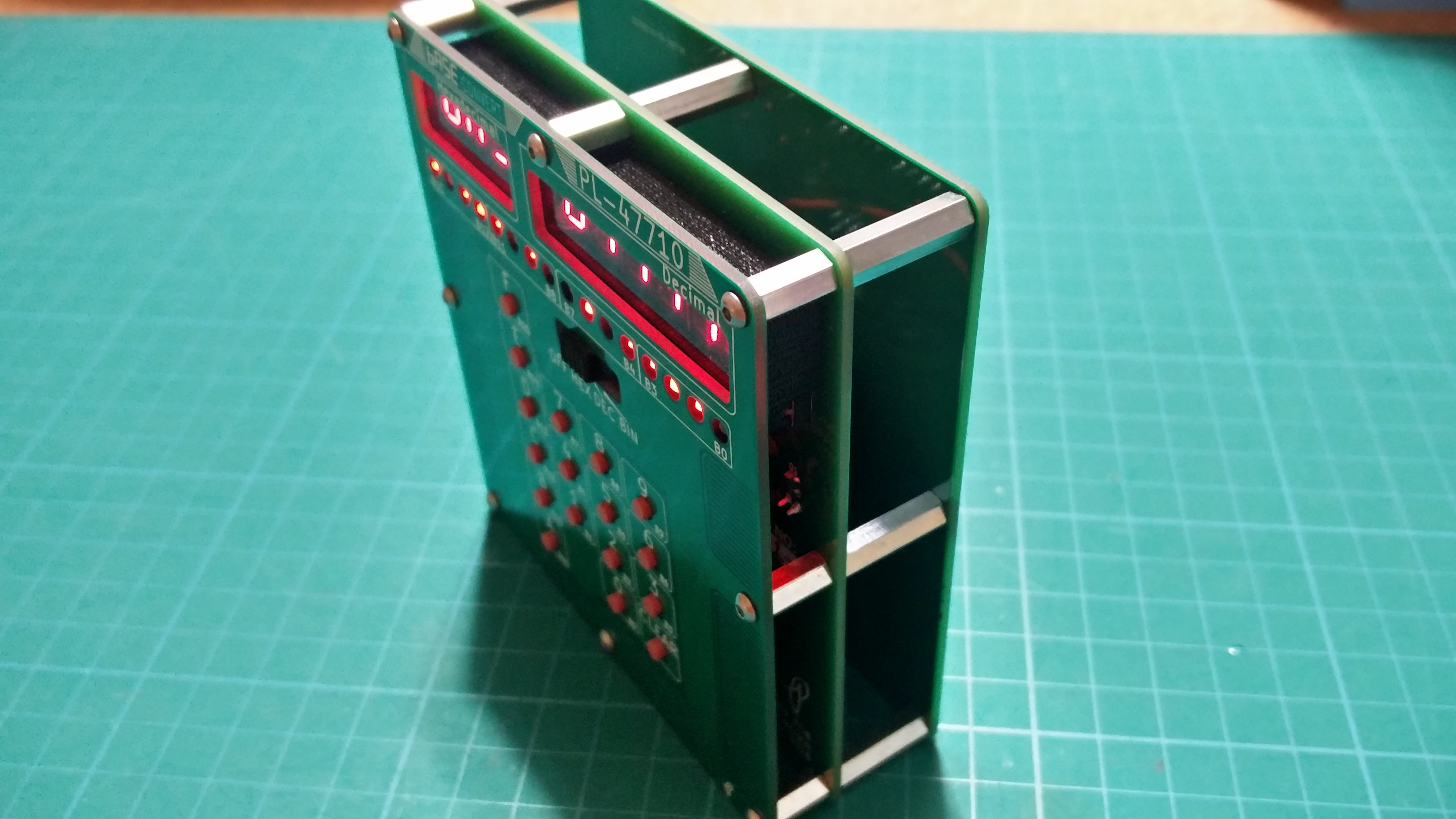
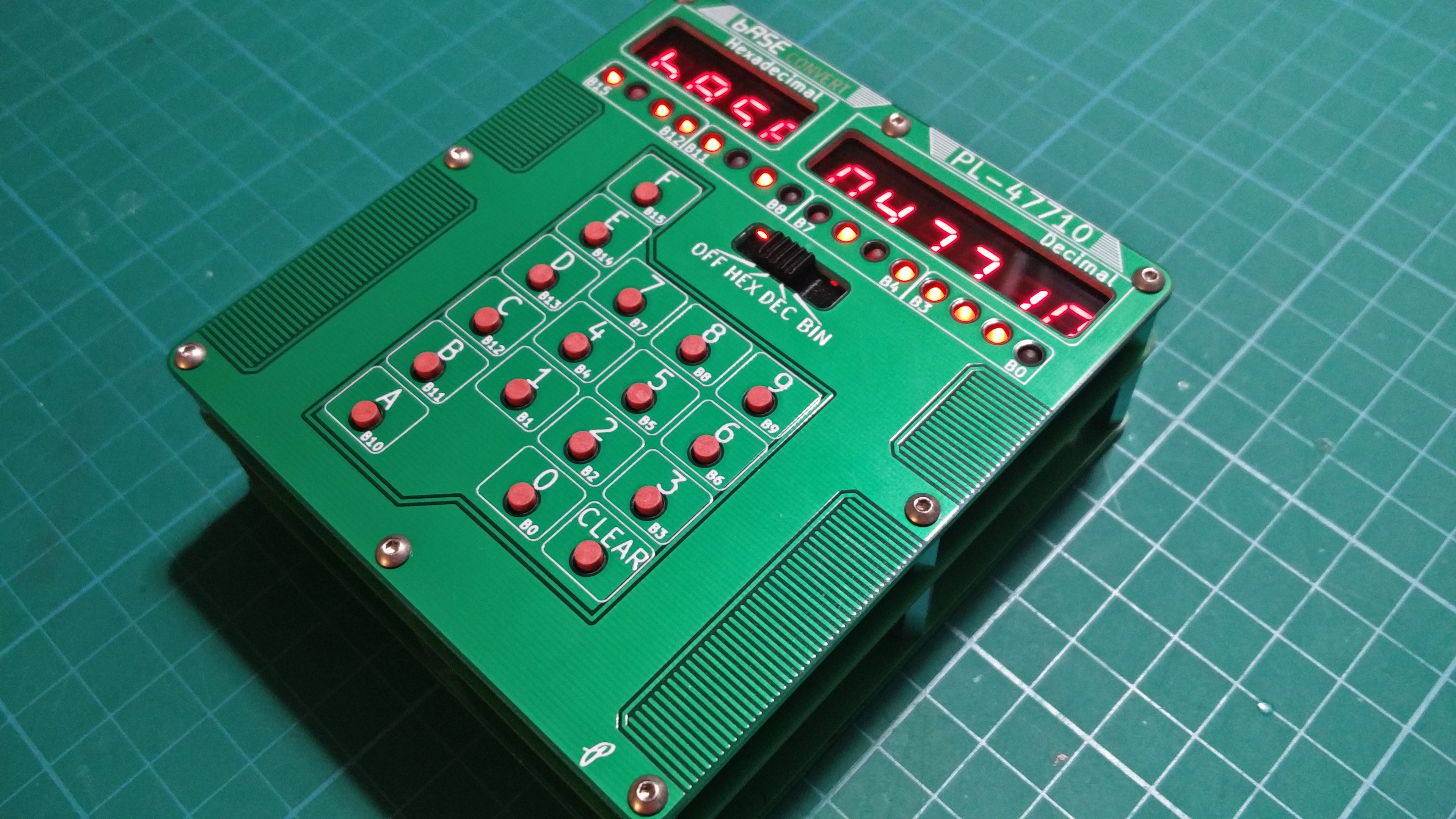
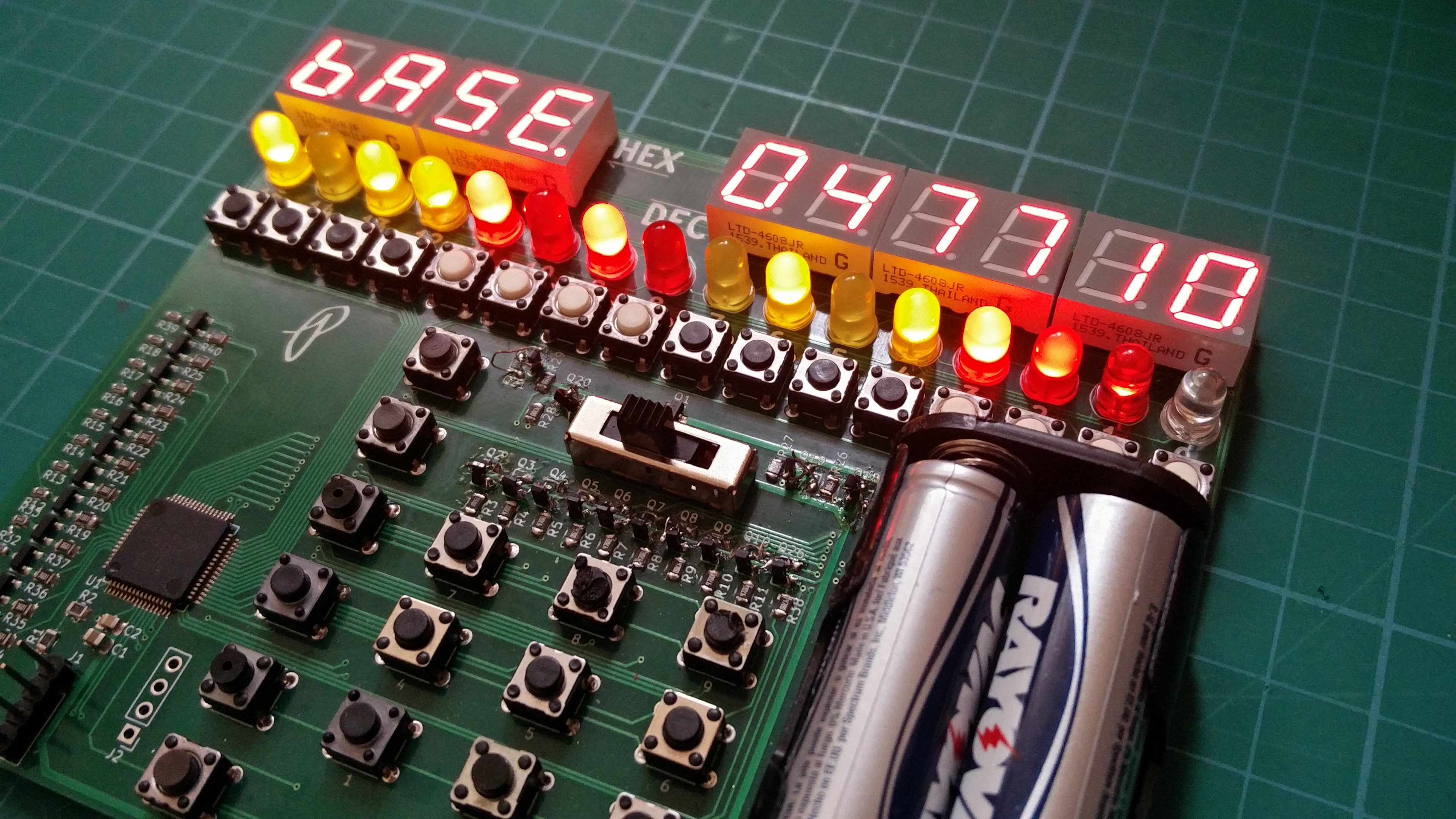
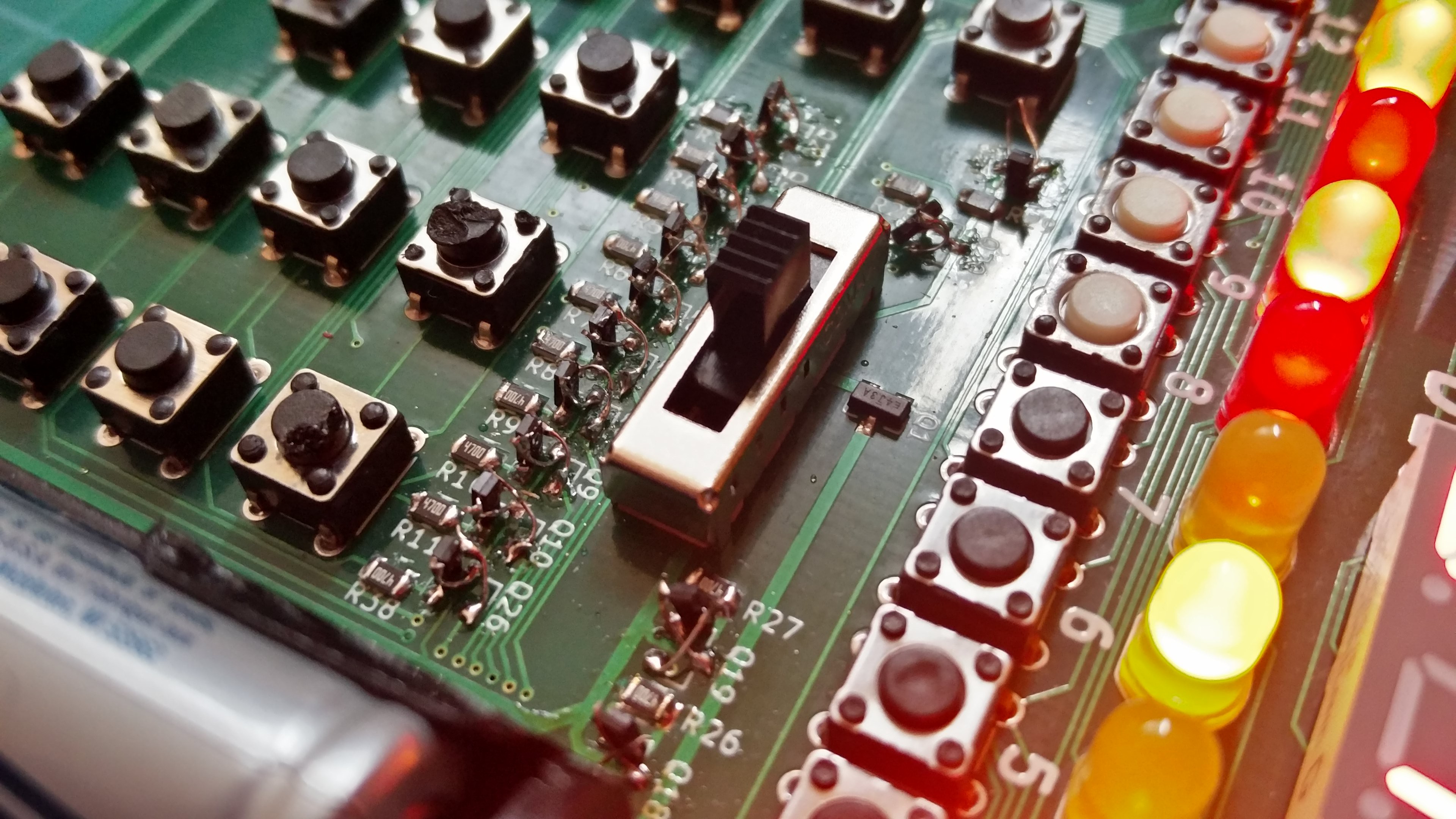
07/30/2018 at 01:25 • 5 commentsAfter having to wait for resistor arrays since I placed the wrong footprint size on the main PCB I have finally fully assembled a Rev A.
![]()
![]()
I did run into a few quick fixes such as things I should add to the silkscreen. I also found out after much frustration that there needs to be a 1k resistor on each PNP transistor between the base and emitter otherwise 3.3V is not enough to turn off the display. I hand corrected the above but issues with the 3.3V LDO are making me consider scraping running from 4xAA anyways and sticking with 2xAA or possibly a LiPo for Rev B. I found that the voltage from the LDO is 4.1V and I suspect it has to do with adding the 1k resistor to the PNPs. I have enough to assemble 5 more so the next one will use 2xAA and skip the LDO, I will have to see if the display is bright enough.
Anyways it is nice to be able to hold the real thing instead of staring at a render in FreeCAD.
-
Revision A on Order
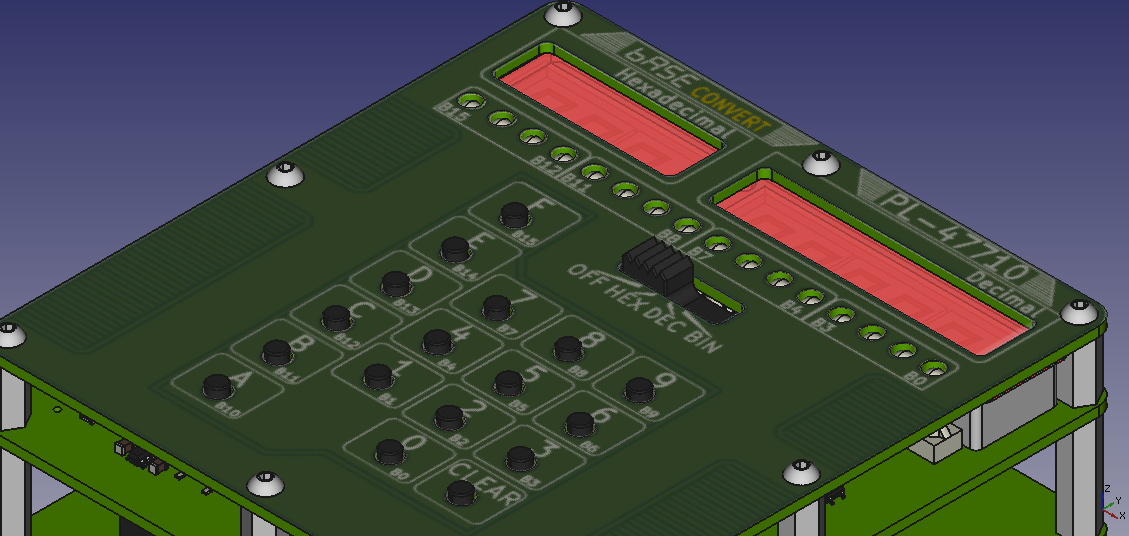
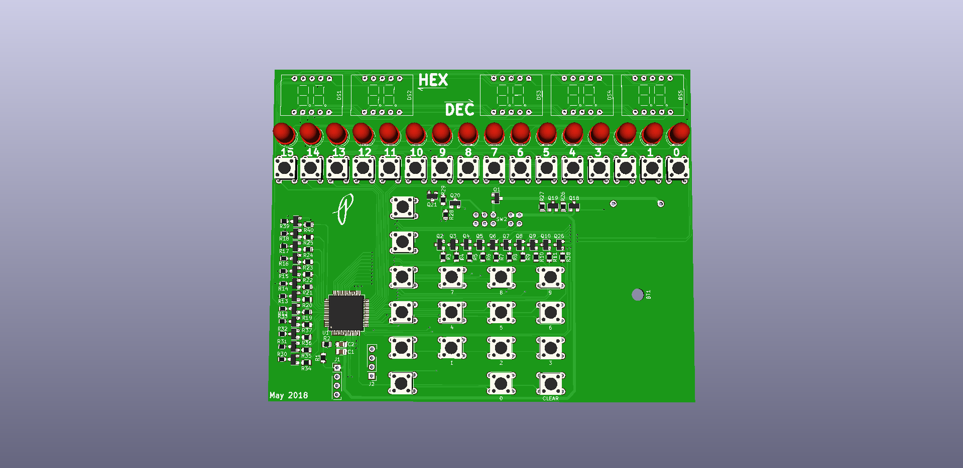
07/14/2018 at 11:30 • 0 commentsRevision A PCBs and hardware is on order. There are a few changes to this revision from the first prototype. First the separate binary keypad input had to be removed so that the PCB could be 100mm wide or less. There is a significant increase in cost when ordering PCBs from China when the board moves from 100mm on any side to 101mm or greater. Don't worry binary input is still possible using the decimal/hex keypad, see the silkscreen in the renders below for the layout.
The 7 segment displays also shrank in size to fit in the new board width. I was able to find transparent red acrylic to place in front of the 7 segment display, the previous revision looked so much better after testing it out with a piece of the acrylic. To increase display brightness the batteries increased from 2x to 4x AA's for a few more volts to feed to the LEDs.
Another minor change was switching from the MSP430FR4133 which can drive an LCD to MSP430FR2033 that cannot drive an LCD since this design does not use an LCD, this shaves a few cents off the BOM cost.
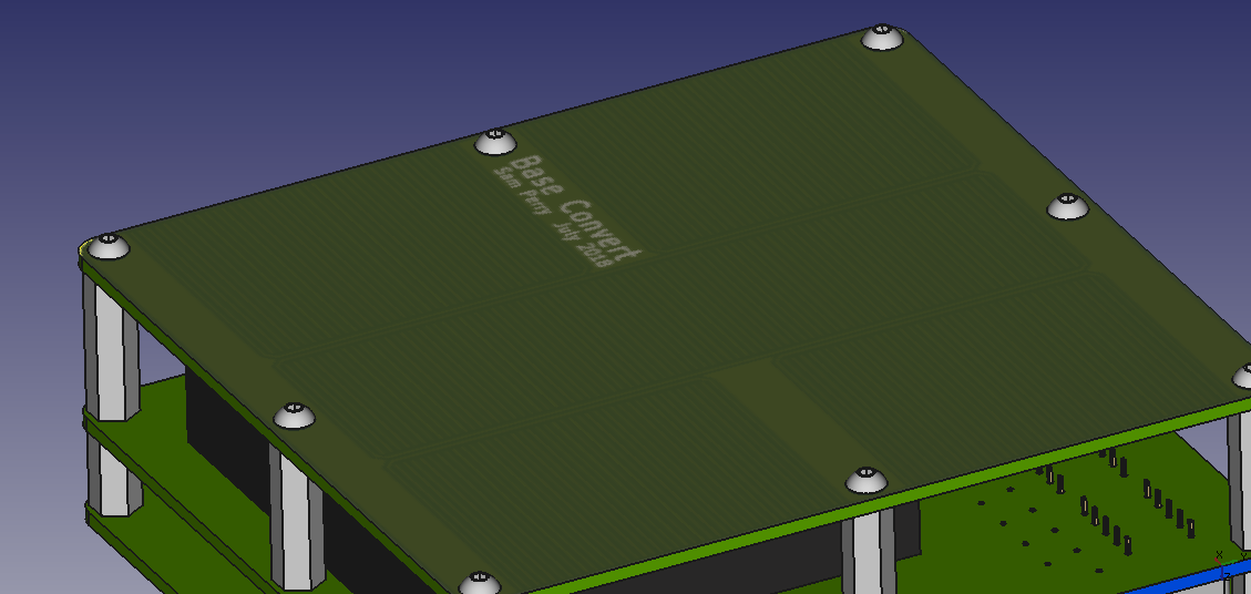
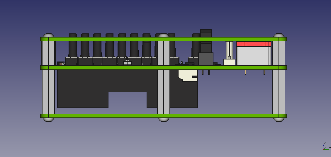
Wanting this revision to look a little more polished I will have a front and back PCB on standoffs to make up a case. I played around with the silkscreen and copper layers to add a bit of decoration.
Below are renders of the assembly using files exported from KiCAD and then assembled into FreeCAD. I can't wait to look at the real thing.
![]()
![]()
![]()
-
PCB Assembly and Firmware
06/05/2018 at 00:08 • 0 commentsI finally got the boards assembled and have completed usable firmware that does more than just test out the display. I may be biased but I am liking what I created. The current firmware (available on GitHub if you want to see my inefficient coding skills) allows input of hexadecimal, decimal, and binary numbers using the keypad for the HEX/DEC and the buttons under the binary display for binary input. After finding some faulty tactile switches the inputs work very well considering the mess of code polling them. There is also a clear button along with an input mode selection switch that also acts as the power switch.
![]()
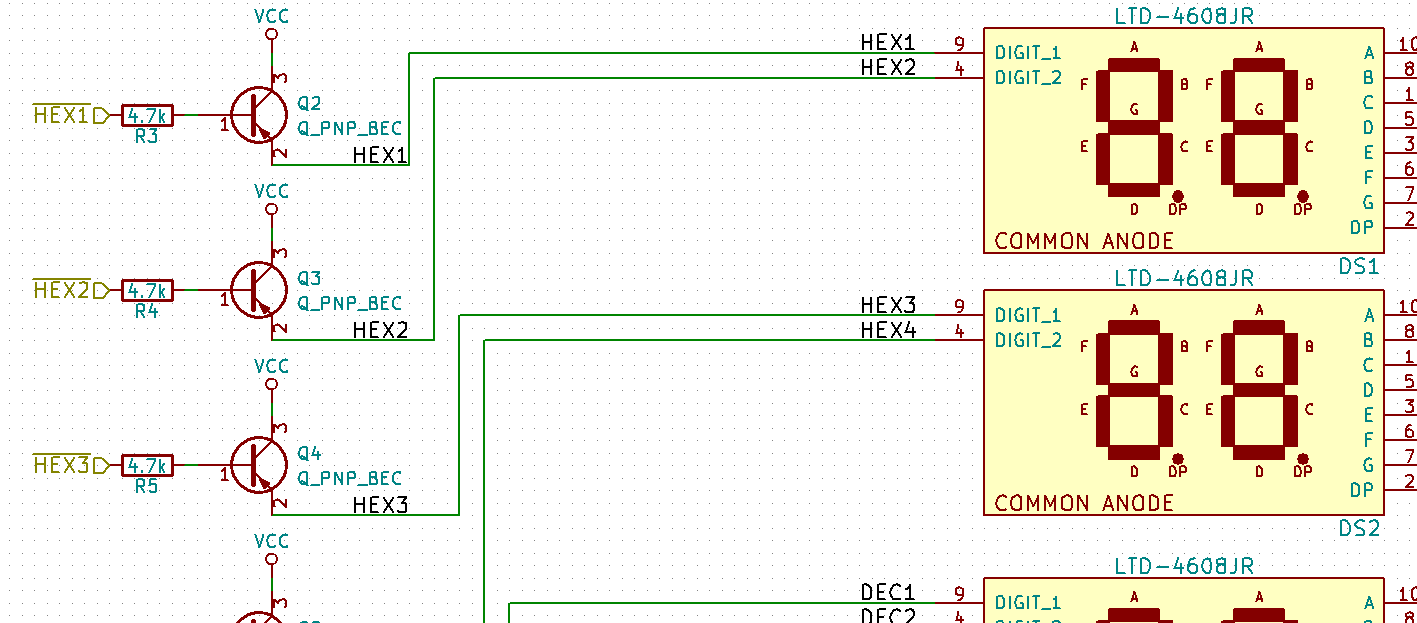
I ran into a few issues with the hardware and firmware that will have to be updated in the next PCB. For starters I must have completely forgot how to wire up a PNP transistor when capturing the schematic since I connected the collector to Vcc and not the emitter. This was the cause of a dim display that had me stumped for a few hours. I even dragged out my copies of The Art of Electronics 2nd and 3rd edition to read through the first few sections of the chapter about bipolar transistors and it was only after I sat down with pen and paper to see if I had chosen incorrect resistor values that I glanced at the PNP transistor hookup reminder on my trusty Adafruit PCB ruler that I noticed that I had wired them up wrong in the schematic. I searched on Digi-Key hoping to find SOT23 PNP transistors with BCE pinout with no luck. I ended up flipping the transistors on there ends and soldering thin magnet wire connections.
![]()
This will be fixed immediately and hopefully will be something I don't forget to check not just for this project but for future ones.
![]()
Another major issue, but this one is not circuit breaking, is that I should have wired up the keypad to ports 1 and 2 only since they are the only ports on the MSP430FR4133 with interrupt capabilities. I wrongly assumed all pins could generate an interrupt but was soon proved wrong when Code Composer Studio when WTFLOL at my attempts to enable interrupts on ports 8 and 5.
![]()
Speaking of buttons I think the next revision will have the binary and keypad share the same pins. Maybe I can get fancy and disable the keypad not being used for the current input mode using external circuitry but I would not count on it. It may not be and issue if the bit0 button also inputs a 3 during hex/dec mode.
I also have some layout to fix so that it is easier to press the buttons. Why did I place the battery holder on the top where it can block access to buttons? I may also rethink the BIN display along with the input for the BIN display. Thouse 16 buttons take up a lot of space and make the board size unnecessarily wide. I was toying with using the keypad as input, ie key 9 would toggle bit9. I don't know though, I like toggling the bits with the key right under them.
If anyone reading this knows of any PNP bipolar transistors in a SOT23 package where pins 1-3 are base, collector, and emitter respectively let me know. It would be nice to not have to throw away the 4 remaining prototype PCBs.
-
PCB On Order
05/15/2018 at 23:24 • 0 commentsI have ordered a set of 5 PCBs so that I can start developing the firmware. I was going to breadboard everything but it was becoming a tangle of unmanageable wires with only 4 digits, 6 more along with 16 LEDs would be a monster. PCBs are so cheap and will save me the headache of wondering if my wiring of the breadboard is wrong so there is no reason for this project not to jump straight to a PCB.
I am not happy with how large I had to make the board and want to try to stick to the cheaper 100mm square PCB size or less in a future version.
I will have to abandon the 6mm tactile switches for the binary input to get the width down. If anyone has any suggestions for switches let me know. I was hoping to find illuminated ones but they are about the same size as the 6mm so no width savings. I may have to play around with not lining them up in a nice row, it bothers my love of straight lines but it may be necessary.
I also will have to see if having transistors to drive the LEDs (at least on the sink side) are necessary. If not then it could save a lot of wiring and components! Otherwise I will look into transistor arrays (ULN2003A?) or other options.
I like the 7 segment displays I have chosen, the LTD-4608JR 10mm 2 digit 7-segment display from LiteOn, they are super bright with very little current. I don't see a reason why these will not be used in the final design.
Here is a render from KiCAD minus the components that I could not easily find 3D models for.
![]()
-
Getting Started
04/14/2018 at 15:30 • 0 commentsI need to get motivated and focused on this project.
I have a MSP430FR4133 launchpad and have purchased a few 7-segment displays to experiment with. While building this project I am also learning how to program with the MSP430 series of microcontrollers so I have to start off small and work my way up. I have one of the displays setup on a breadboard and have the wiring complete. I just have to open up Code Composer Studio along with the MSP430FR4133 datasheet before getting distracted by another project... oh look shiny.
Base Convert
Simple desk/handheld calculator to convert between hexadecimal, decimal, and binary.