Pano Logic Zero Client G1
Documenting the internals of the first gen for hobby use
Documenting the internals of the first gen for hobby use
To make the experience fit your profile, pick a username and tell us what interests you.
We found and based on your interests.
Originally published here: https://tomverbeure.github.io/rtl/2018/11/26/Racing-the-Beam-Ray-Tracer.html
https://player.vimeo.com/video/303938705
One of the most exciting moments of a chip designer is the first power-on of freshly baked silicon. Engineers have been flown in from all over the world. Debug stations are ready. Emails are being sent with hourly status updates: “Chips are in SFO and being processed by customs!”, “First vectors are passing on the tester!”, “First board expected in the lab in 10mins!”.
Once in the lab, it’s a race to get that thing doing what it has been designed to do.
And that’s where the difference between a telecom silicon and a graphics silicon becomes clear: when your DSL chip works, you’re celebrating the fact that bits are being successfully transported from one side of the chip to the other. Nice.
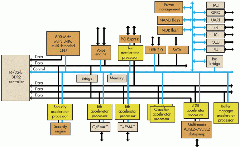
But when your graphics chips comes up, there’s suddenly a zombie walking on your screen. Which is awesome!
All of this just to make the point: there’s something magic about working on something that puts an image on the screen.
So when I started to reverse engineer the Pano Logic device, getting the VGA interface up and running was the first target. Luckily, it’s also far easier to get going than Ethernet and USB.
After my short RISC-V detour, instead of getting back to Ethernet, I wanted get a real application going, and since ray tracing has been grabbing a lot of headlines lately, I wondered if something could be done.
My first experience with ray tracing was sometime in the early nineties, when I was running PovRay on a 33MHz 486 in my college dorm. And when thinking about a subject for my thesis, hardware accelerated ray-triangle intersection was high on the list but ultimately rejected.
On that 486, you could see individual pixels being rendered one by one, far away from real time, but when you do things in hardware, you can pipeline and do things in parallel.
Compared to today’s high-end FPGAs, the Pano Logic has a fairly pedestrian Xilinx Spartan-3E, but the specs are actually pretty decent when compared to many of today’s hobby FPGA boards: 27k LUTs, quite a bit of RAM, and 36 18x18bit hardware multipliers.
Is that enough to do ray tracing? Let’s find out…
Pano Logic was a Bay Area startup that wanted to get rid of PCs in large organizations by replacing them with tiny CPU-less thin clients that were connected to a central server. Think of them as VNC replacements. No CPU?...
Read more »After a vacation and lots of World Cup quality time (Go Belgium!), the pace on the Pano Logic project has been picking up again.
Audio playback was always high on the list and there’s a lot of progress on this front: I can play a 1KHz test tone when plugging in my headphones!
For reasons unknown, the speaker does not work, even after a long evening of trying as many settings as possible.
Still, with this milestone, I’m one step closer to using the Pano Logic box as a mini game console.
The interface between the NXP ISP1760 and the FPGA has been completely mapped… I think. The chip has a 16-bit and a 32-bit mode. On this board, the 16-bit mode is used. I expect that it will be quite a bit of effort to get USB going. First step will simply to be get the FPGA to read and write registers and then we’ll see where it leads us.
Even though the ISP1760 has a built-in 3-way hub, there is an external SMSC USB2513 hub. I was told that the ISP1760 has some bugs in the hub, so that probably explains the presence of this SMSC chip.
The SMSC chip has an I2C interface, but was only able to identify a reset and a clkin signal between the FPGA and the SMSC chip. It’s possible that the default configuration is sufficient and that no further configuration is necessary.
A bunch of connections between the Micrel KSZ8721BL Ethernet PHY and the FPGA were identified as well. However, there are some signals that seem to be suspiciously not connected (e.g. eth_txcand eth_pd_).
Getting Ethernet to work would be incredibly nice, but it’s a pretty complex undertaking and lowest priority.
I may spend a bit more time on getting the speaker to work, but the true challenge ahead will be USB: the Pano Logic box is almost useless if you can’t connect a keyboard to it.
(Originally published here.)
The most important resource are the connections between the FPGA and its surroundings. That information is captured in the top.ucf file.
Right now, I have the following interface have been completed:
This interface is not only complete, but there is also RTL that successfully programs the generator into creating the pixel clock for 1080p VGA video timings. The RTL can be found here.
Nothing is more fun that having your own design generate and image and send it to a monitor, so this one had full priority. With this interface figured out, we can create the RGB signals. But that’s not enough! We also need:
VGA doesn’t have HSYNC and VSYNC embedded in the RGB signals: it has separate pins for that. In order to create video, I had to figure out how the FPGA controls HSYNC and VSYNC.
In the process, a lot of other signals were also identified: USB signals, VGA DDC I2C pins, button, and LED control. No project is officially alive without a blinking LED.
Audio bringup soon!
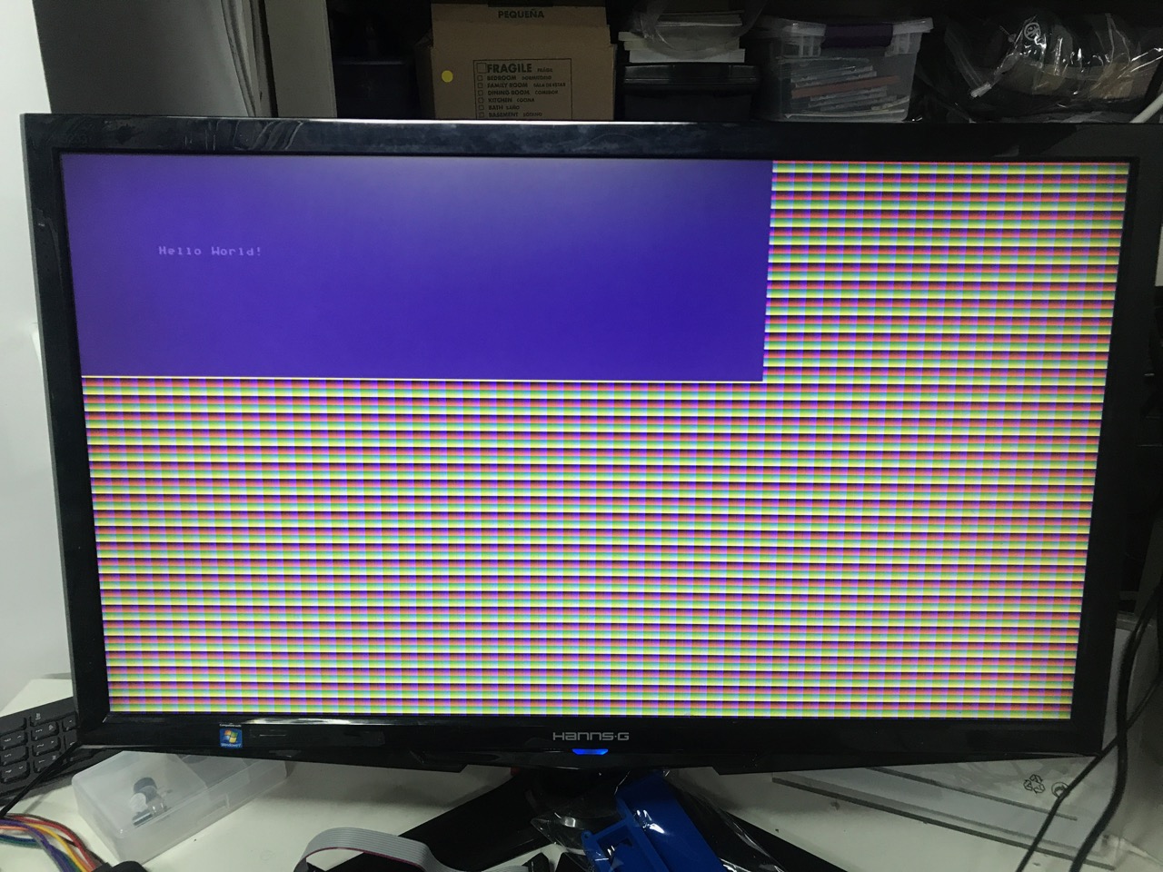
With everything in place to create video signals, and some pretty simply RTL code, you can now see the following:
With video figured out, it’s time to move to bring up other interfaces. Audio is quite simple, so that’s high on the list.
But we really need a CPU to make that kind of bringup easy. For example, the Wolfson CODEC is configured through I2C. I’m already using a bit-banged I2C master on a Nios2 for my eeColor Color3 project. I want to do the same here.
That’s why the project now also has a VexRiscV!
A seperate post will go into the details about the specifics of this RISC-V core, but the most important reasons to choose this one over the ubiquitous PicoRV32 are:
It’s totally possible to make it work with relatively minor RTL edits, but that was only true when you don’t use using the HW multiplier. Using the multiplier breaks the terrible Xilinx software. Meanwhile, ISE was able to grok the VexRiscV on first try, multiplier and all.
Or better, the PicoRV32 is really slow, coming in at 3 to 7 cycles per instruction. The VexRiscV is just as configurable as the PicoRV32 and can go at one cycle per instruction without trying very hard. (It’s currently running at 2 cycles per instruction though.)
It’s not that we need a faster CPU for our current purposes, but the amount of logic resources for the VexRiscV is almost the same as for the PicoRV32. And it’s fun to explore different cores. So why not?
At this time, the CPU is only used to blink the LEDs (yay!). That’s because some other infrastructure is necessary to really start using it: as way to tell the user what’s going on. That’s why the following was developed:
And as of today, there is also a character generator:

The GitHub repo is always in a state of flux, but that example can be generated by syncing to this commit.
The screen buffer hasn’t been connected to the CPU yet, but once that’s done, everything will be in place to start driving other parts of the PCB.
(Sadly, the Commodore 64 font will be replaced by the vintage IBM 8x12 character set, since the latter is ASCII mapped out of the box.)
Lots of progress. More to come!
Next step: getting audio-out to work.
(Also published here.)
After transcribing the data from previous reverse engineering efforts , and an insane amount of effort to Xilinx ISE 14.7 to work with my Digilent JTAG clone, I've started for real with the mapping out the pins of the FPGA.
The PCB is remarkable in that all the balls of the FPGA and the SDRAM BGAs have an accessible via.
That makes it really easy to figure out all the connections between them. So that's the work that got completed first.
The remainder of the chips are some form of a QFP. You can figure out the connections either by installing a ChipScope (similar to how I did some of the eeColor Color3 pins), but that doesn't work inputs to the FPGA.
It'd be much easier to remove the FPGA from the board and Ohm things out that way.
But that'd be a deliberate act of violence and destroy the board.
Well... I bought a lot of 5 of them for $45.
So off when the FPGA. Feel dirty, man.
I've now mapped out the full connection between the FPGA and the TI VGA Out chip. At this point, this should enable me to send an image to a monitor, but VGA is so old now that I couldn't find a VGA cable at home (or even at work.)
While waiting for a cable, I've started mapping out the USB host chip as well.
(Also published here.)
The first step has been completed: acquisition of the goods!
I mistakenly first bought a gen 2 for $10, which can't be used due to lack for free Spartan 6 license.
But today, a lot of 5 gen 1s arrived which were purchased for a whopping $45 on eBay. Here's the full family!
$9 per device is not bad, but I could have done better: there was another offer on eBay of 33 devices for the low low price of $150, though 9 of those were gen 2. Still 24 useable unit would be only $6 each.
But 5 should be sufficient to break a few and still have enough left for real projects.
The real work will have to wait until I get bored with the Color 3 work.
Create an account to leave a comment. Already have an account? Log In.
Incredible! Very cool to see this running!
I love how you're combining a bunch of hacks.
But you know that the next step is to get this going with USB, right? ;-)
Is audio working as well?
Yea audio works, and it's LOUD... Too loud. my wife hates it. That's a big incentive to get an I2C port expander going so I can add a volume control and/or mute button.
Tom and Tim have done an amazing job setting the ground work for a newbie to get going. I bought my first batch of G1s and G2s (3 each) after reading Tom's hackaday article. Since then I've been porting MikeJ's Pacman hardware simulation to the G1. Video is up and running and I'm working on the Joystick interface. I'm also learning SpinalHDL along the way.
Interesting project Tom! Looks like you have really got to grips with the G1. As you say, this is great since the free Xilinx ISE works with it, but the Spartan 3 is really long in the tooth, and the G1 config is hard to extend from a hardware POV. Spartan 6 G2 is a much more capable beast which I am concentrating on - you just have to get over the ISE licensing issue :-( Long term solution is to get a FOSS tool chain up and running and bin the truly awful Xilinx software, but I think that is quite a way away.
Getting the Ethernet up is not as big a problem as you might think.
using one of the "opensource" libraries for the Verilog + lwip compiled to run in a "soft" cpu is doable.
I might join you on the pano research,
but I have some excellent "Anobit" FPGA SSD drive pcbs With SATA interfaces
or a set of Japanese video processing PCI boards
so it's a toss up between the various projects...
Using an Ethernet MAC from OpenCores is the approach I plan to take, but it’s still a lot of complexity where everything needs to be right.
I’m currently having fun with a “real” non-reverse engineering project for the Pano, but once that’s done I’ll go back to getting interfaces up and running.
Software from Opencores may be a challenge due to coding standards and documentation (lack of). A couple of possibly useful references: Joel has done some work on getting a UDP code implementation working https://joelw.id.au/FPGA/DigilentAtlysResources and Philipp Kerling did a B.Sc project on developing an open source MAC. Try searching on his name and Tri-Mode Ethernet MAC on an FPGA. S6, but you may find the discussion useful.
You *probably* should know about this dude and his stuff --> http://parkytowers.me.uk/thin/index.shtml
Those are basically small computers. This seems to be like a FPGA board. Whatever processing it had must have run as a softcore in the FPGA.
Yeah, I know -- a lot of "zero clients" have "dedicated hardware" that turns out to be an FPGA. I just thought your interests might overlap into that of the non-"zero" thin client realm... FWIW, ParkyTowers Guy (I don't know his real name) has a couple "zero clients" on that site, and they all (IIRC) use FPGAs inside.
Also, I tinker a lot with those thin clients -- it's a super cheap and easy way to get a low-power Linux desktop, if you don't mind the quirks... I'm actually quite proud of a bugfix I got, having to do with the "openchrome" driver (which supports VIA graphics hardware) and the Wyse C-series clients (formally referred to, usually, as the Cx0 Series, but who's counting...?) -- that was back in 2016, and last I checked, it was still being ignored by Debian/Ubuntu, despite the version that they incorporate (still) being the broken one! (I guess that's partially my fault, since I never went and whined at the Debian devs about it... but I shouldn't have to, IMO...) The bug is #91966 in the "openchrome" bugtracker, if you want to look it up.
If it weren't for that one damned issue, those Wyse Cx0 clients would really be the best value you can currently get on eBay (if you don't mind that they're 32bit machines). But compiling a graphics driver from Git sources is not for the average user... ;) so it's more the Clientron U800-series that I have to recommend. That one gets a lot of rebrands. It's a "Devon Clientron" U800, a Dell FX170, a 10ZiG RBT-616V, and probably a bunch of others, too... basically a little N270-based box about the size of a good mystery novel ;) still 32bit, of course, but it's a rock solid design and it doesn't have too many unexpected surprises... the trick is to get a sizable drive in there, though -- SD card in an adapter works, if you can run from RAM and put up with a slow boot ;)
Not the project owner, just thought you weren't aware of the different class of this device. I've been tempted to pick up one of the x86 thin clients recently. PhilsComputerLabs on Youtube has put out some videos of one that can be used as a retro Dos gaming box, even with room for one expansion card.
If this zero client is fully reverse engineered it'd be great if it becomes possible to do some of the retro cores like the Mister fpga board has.
My interest is not in small clients, but in doing fun stuff with FPGAs. The Pano Logic client is diet cheap on eBay and it has as many advanced IO capabilities as most dev kits that go for a much higher price.
Become a member to follow this project and never miss any updates
By using our website and services, you expressly agree to the placement of our performance, functionality, and advertising cookies. Learn More
 ziggurat29
 Marcel van Kervinck
 Matt Stock
Packman is up and running on the Pano G1. The code is here: https://github.com/skiphansen/pano_man.