Bradley Worley
-
PyPPMv2 is on it's way!
09/04/2014 at 22:18 • 0 commentsAlright folks, I've finally ordered the components and circuit board for the PyPPMv2! I'm glad I went through the BOM and board one final time, because I found a few flubs that would've been tricky to overcome after the boards were fabbed...
Also, the AD5752R DAC chips were out of stock on Digi-Key! I had to settle for the pin-compatible (after a bit of firmware recoding) AD5754R quad DAC, which is about twice the price. I'll pay that, if it means getting the PyPPMv2 done sooner. :)
Everything's looking good for a new version of the PyPPM, and I'm stoked to see how it comes together. I'll keep y'all posted, of course. ;)
-
Next video coming soon!
09/04/2014 at 02:56 • 0 commentsWith the ATmega32U4 chips in my possession, it's time to do one final error check on the current PyPPMv2r1 board and order some boards and components. Exciting!
Truthfully, every time I order a new board, I feel like I'm missing some mistake. Imagine that feeling you get leaving the house for a long trip, multiplied many-fold. Yeah. :)
On the video front, the plan is now to post a substantially longer video on Friday or Saturday, or both. I'll cover basics of NMR, PPM's, design of the PyPPMv1, and new features in the PyPPMv2. But it's definitely gonna be a weekend thing; the day job cramps my video making schedule...
-
What's to come for PyPPMv2
09/02/2014 at 01:45 • 0 commentsHey all! I'm super stoked to be an official Hackaday Prize semifinalist, and I figured I'd film a quick video to describe my plans for the coming weeks. Check it out, and let me know what you think!
-
Finally on GitHub, and it feels good
08/16/2014 at 15:09 • 0 commentsThe PyPPM source tree (that's right, all of it!) has finally been ported from my lazy system of web-hosted tarballs to a proper GitHub repo: check it out here.
Of course, all the source code is released under the GPLv3, and all board designs are under the Creative Commons CC-BY-SA. This is probably a good moment to note that everything in this project is open source, and everything used to design the project is also open source. (Went a little crazy with the formatting there...) For example, gEDA gschem and PCB were used for schematic capture and board design, and vi (a.k.a. the greatest text editor of all time, cue flame war) was used for all code. PyPPM doesn't rely on many external libraries, but those that it links against (avr-libc, libsndfile, freeglut, mesa GL, GTK+3, GNU Octave, Python, gnuplot, etc.) are also FOSS. Long story short, it's all open, so enjoy!
Now I need to start pushing all my other projects to GitHub too! ;)
-
m32u4's *still* backordered...
08/10/2014 at 00:34 • 1 commentWell, I was hoping that the ATmega32U4's would've shipped by now, but Digikey just sent me an email to say that the ship date has been pushed back yet again!
Awesome. :P Once the chips ship, I'll order the rest of the design. And of course, I'll keep y'all posted the whole way through.
-
It's a learning experience...
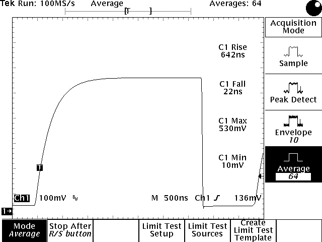
07/19/2014 at 18:06 • 0 commentsThis was my first time using an optocoupler in my design, and I'm realizing I should've read the datasheet more carefully. :)
![]()
The above scope capture is the /CS (chip select) waveform as seen by the AD5328 DAC on the shim control board. It seems my hasty choice of 12.4k pull-up resistors was a far cry from the 350 ohms recommended in the optocoupler datasheet.
It's anything but a problem, however. The optoisolated capacitive switch bank in PyPPM 2 can be clocked at 125 kHz (fCLK/128) without a problem.
-
All for a multiplier!
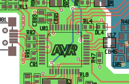
07/18/2014 at 01:51 • 0 commentsI was writing the firmware for PyPPM 2.0 when I was informed (by the compiler, rather rudely) that the ATmega32U2 doesn't support MULSU, or any multiplication for that matter!
I had no choice but to redesign around the ATmega32U4...
![]()
I know the silkscreen logo will get covered by the chip, but I don't care; it just looks too cool not to keep. :)
-
Direct Digital Synthesis, anyone?
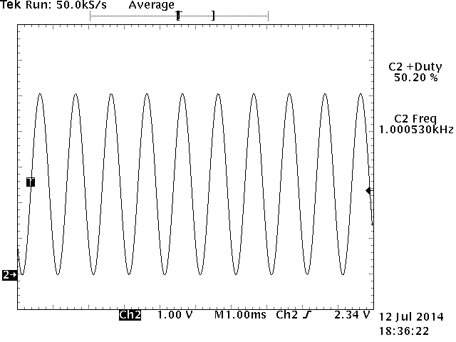
07/13/2014 at 02:52 • 0 commentsI wrote my first assembly code this past week, and it felt pretty good...
![]()
Using an old PPM prototype that had a 12-bit DAC on board, I wrote a bit of code that outputs a frequency tunable sine wave. The overall design is similar to Jesper's ATmega8 DDS code, but mine is designed to (A) be intermixed with my pre-existing C code and (B) operate inside a 125 kS/s timer/counter interrupt.
One step closer to PyPPM 2.0! :D
-
Brace yourselves... revisions are coming
07/09/2014 at 22:33 • 0 commentsAfter some very insightful conversations with other Projects members on the PyPPM design, I've made the decision to add several new features to the final version of PyPPM, which I'll officially call PyPPM 2.0.
Consider this my own little unofficial RFC. I want to know what you think about the features and the new design, before I've finalized it. Here's a quick overview of what's to come:
- Capacitive tuning: By turning the sensor coil into part of a resonant tank circuit, the experimenter can simultaneously increase signal to noise and reduce unwanted interference from mains. The PyPPM will allow for 65,536 different digitally selectable capacitances to be placed in parallel with the sensor coil.
- Integrated shimming: Instead of requiring a separate shim control board (see previous posts) to homogenize the magnetic field, PyPPM will have a dedicated 250 mA shim output.
- Adiabatic polarization: PyPPM will support a secondary transmit coil output that can source and sink 1.0 Amp, controlled by a 16-bit DAC. Sample rates of 100 kS/s should be easily achievable.
- Flexible experiments: More on this below. It's exciting!
So, without further ado: the PyPPM 2.0 block diagram overview:
![]()
Oh, and the latest board design :) Like the logo? (It's a proton)
![]()
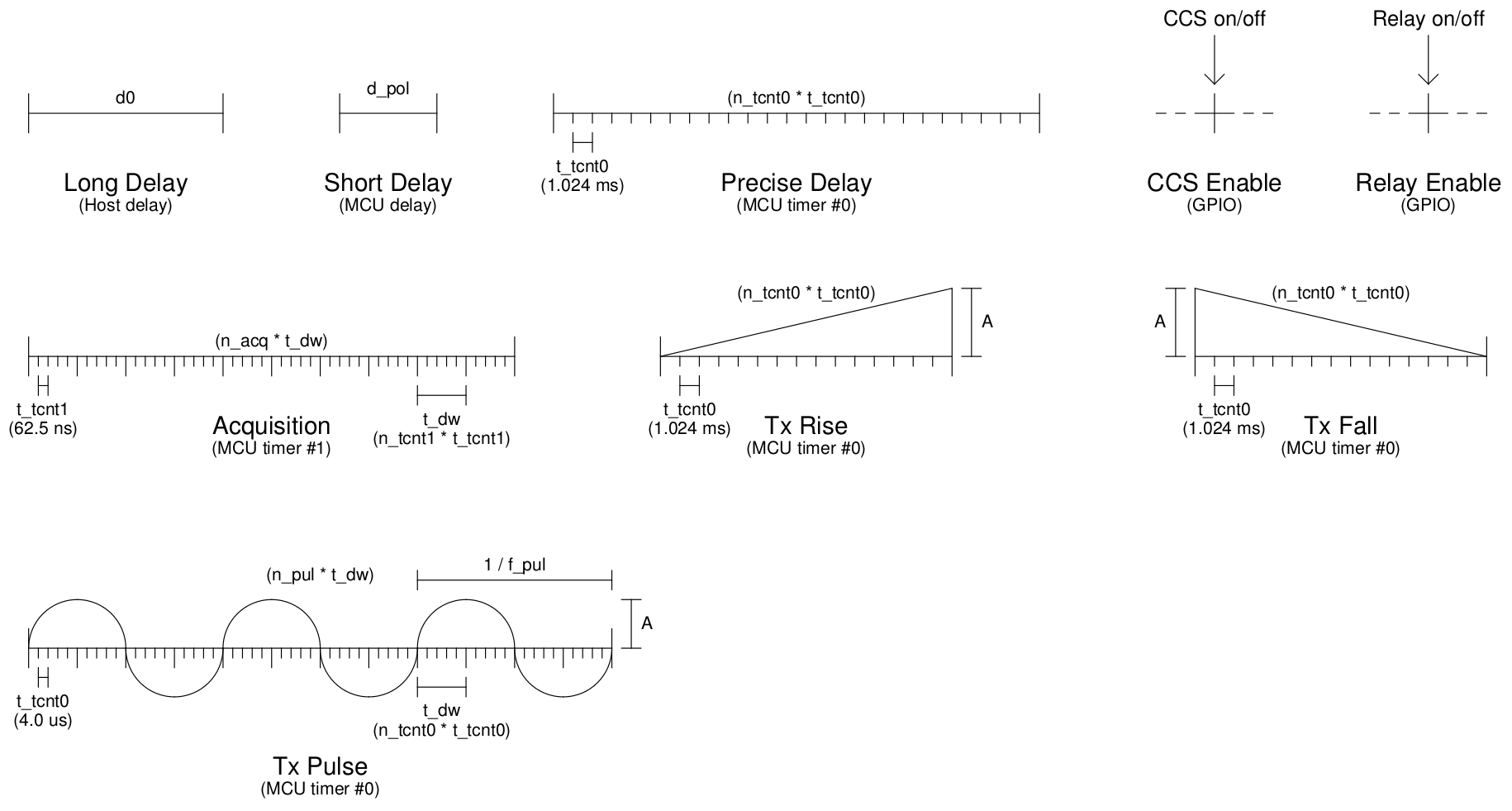
One of the most exciting features of the new PyPPM design is the opportunity to accept "pulse programs", which are small sets of commands that flexibly describe the details of any given experiment. Instead of having a hard-coded "bang-bang" non-adiabatic experiment, the PyPPM will accept any sequence of pulse program commands and parameters and interpret and execute them on the fly! That means the user can run anything from the simple non-adiabatic experiment, to spin echos, to multi-acquisition Carr-Purcell-Meiboom-Gill experiments or even two-dimensional experiments. Fun!
Here's what the building blocks of the PyPPM 2.0 pulse program language look like:
![]()
TL;DR: PyPPM 2.0 has graduated from a simple magnetometer to a complete Earth's Field Nuclear Magnetic Resonance Spectrometer.
And as always, the latest revisions are available in the PyPPM source code on my website, also linked from this project page. Let me know what you think!
-
Treat your optocouplers with respect
06/28/2014 at 21:22 • 0 commentsI built up the first-revision shim control board (SCB) last night, and in a rush to unit-test each functional subcircuit, I managed to apply 5V (without current limiting) to the input of my LDO-enable optocoupler, bricking the chip and limiting what I could do over the weekend with the SCB... oops!
![]()
If anybody's wondering why I've made a second board for a project that boasts a single board solution, don't fret! The final PyPPM hardware design will re-integrate the PPM and SCB boards onto a single PCB. I'm really excited to start work on the next board design; it'll definitely be a nice challenge!
PyPPM: A Proton Precession Magnetometer for all!
A device for conducting Nuclear Magnetic Resonance experiments at Earth's field