Close
0%
0%

Open Source Science Tricorder

Science in your hand. A pocket-sized instrument capable of visualizing and exploring the world around you.

Similar projects worth following
It is my deep belief that knowledge brings about positive change.

We could live in a world where the same instrument that can show a child how much chlorophyll is in a leaf could also show how them much pollution is in the air around us, or given off by one's car. As an educator and a researcher, I feel that if people could easily discover things about their worlds that were also important social topics, that they would then make positive social choices, like reducing their emissions, or petitioning for cleaner industry in their communities.

By having access to general inexpensive sensing tools, people can learn about healthy leaves, clean air, clouds and the water cycle, energy efficient homes — and visualize abstract concepts like spectra or magnetism.

As a tool for exploration, we can discover things around us that we don't already know. And that's what it's about. Little discoveries, everywhere.

Finals Video

Semifinals Prototype Video

Concept Video

Hardware and System Design

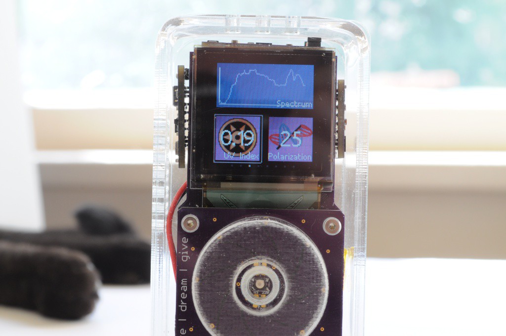
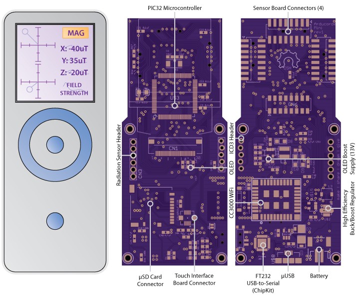
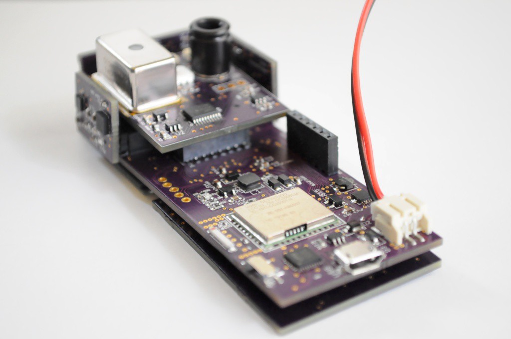
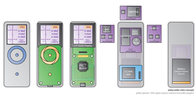
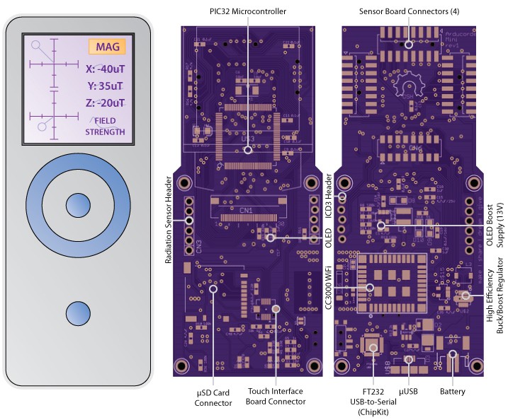
The Arducorder Mini is an Arduino-compatible handheld sensing device, and the next iteration of my open source science tricorder-like device project that's designed to be easy to use, have a large array of sensors, and easy to share sensing discoveries. The Arducorder Mini is designed to foster a community of open source users and development, and is ChipKit MAX32 compatible, which is a port of the Arduino platform to the much more powerful PIC32 family, and makes use of a PIC32MX795F512L with 128k of RAM, 512k of flash, a zippy 80Mhz processing speed, and a fantastic set of peripherals for interfacing to sensors.

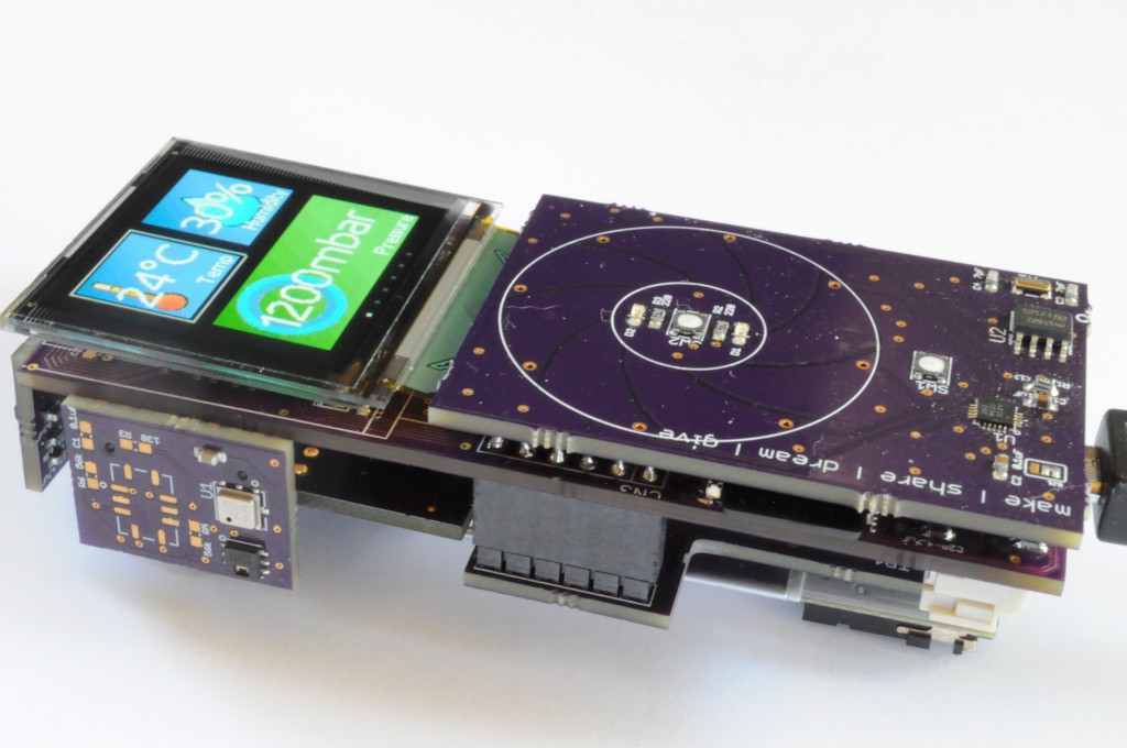
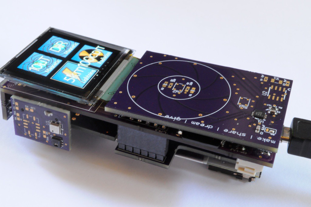
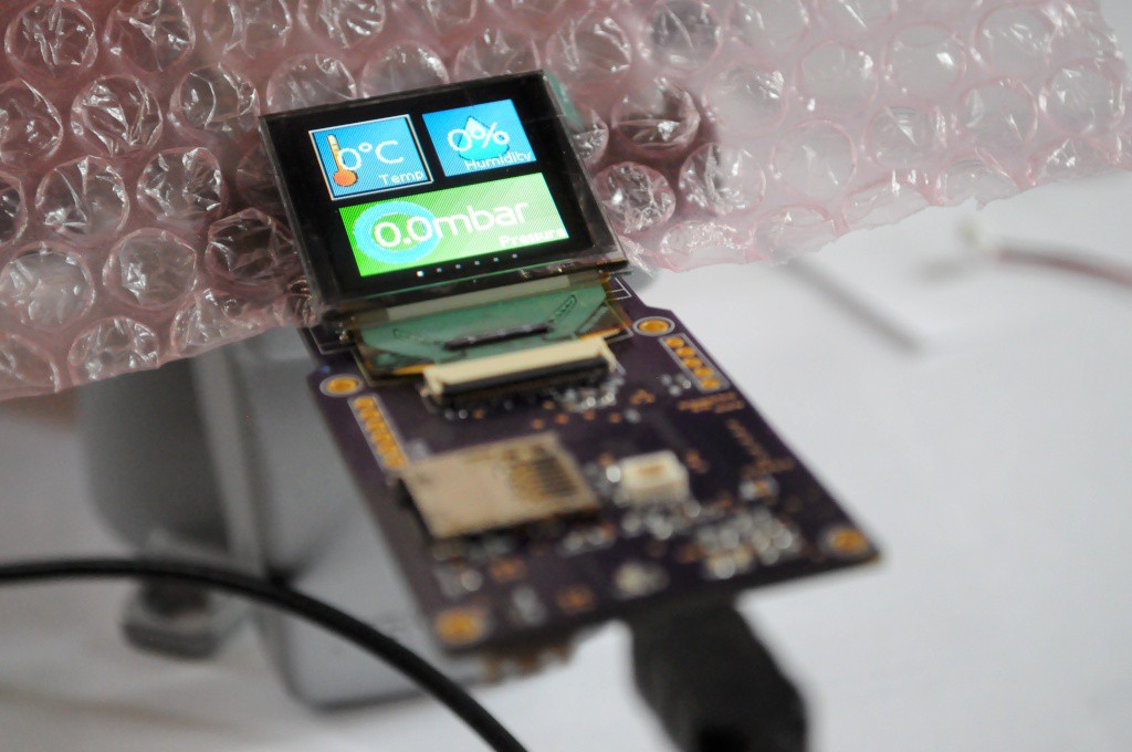
The current prototype is designed to use a 1.5" OLED with 128x128 pixels and 16-bit colour, a touch interface, and connectors for 5 modular sensor boards that each contain several sensors. The sensor boards are designed to be interchangeable and upgradable, so that a large number of configurations are possible with different sensing capabilities and price points.

While the Arducorder Mini is being designed with a wide array of sensing capabilities off-the-shelf, it's also designed to be easy for folks to tinker with and upgrade. Accessibility is a central goal of the project -- If you're familiar with Eagle CAD and have ever made an Arduino shield, it should be easy to design your own sensor board. Using OSHPark and Digikey, the parts cost for a new sensor board (PCB and header, not including sensors) is about $5, which is even less than most protoboards!
Sensing Capabilities

The current prototype has been designed to include the following sensing capabilities:

Atmospheric Sensors

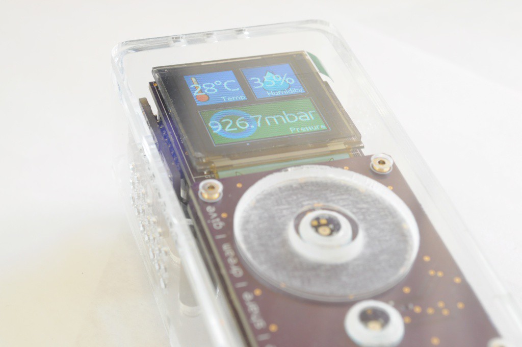
  • Ambient Temperature and Humidity: Measurement Specialties HTU21D
  • Ambient Pressure: Bosch Sensortec BMP180
  • Multi-gas sensor: SGX-Sensortech MICS-6814

Electromagnetic Sensors

  • 3-Axis Magnetometer: Honeywell HMC5883L
  • Lightning sensor: AMS AS3935
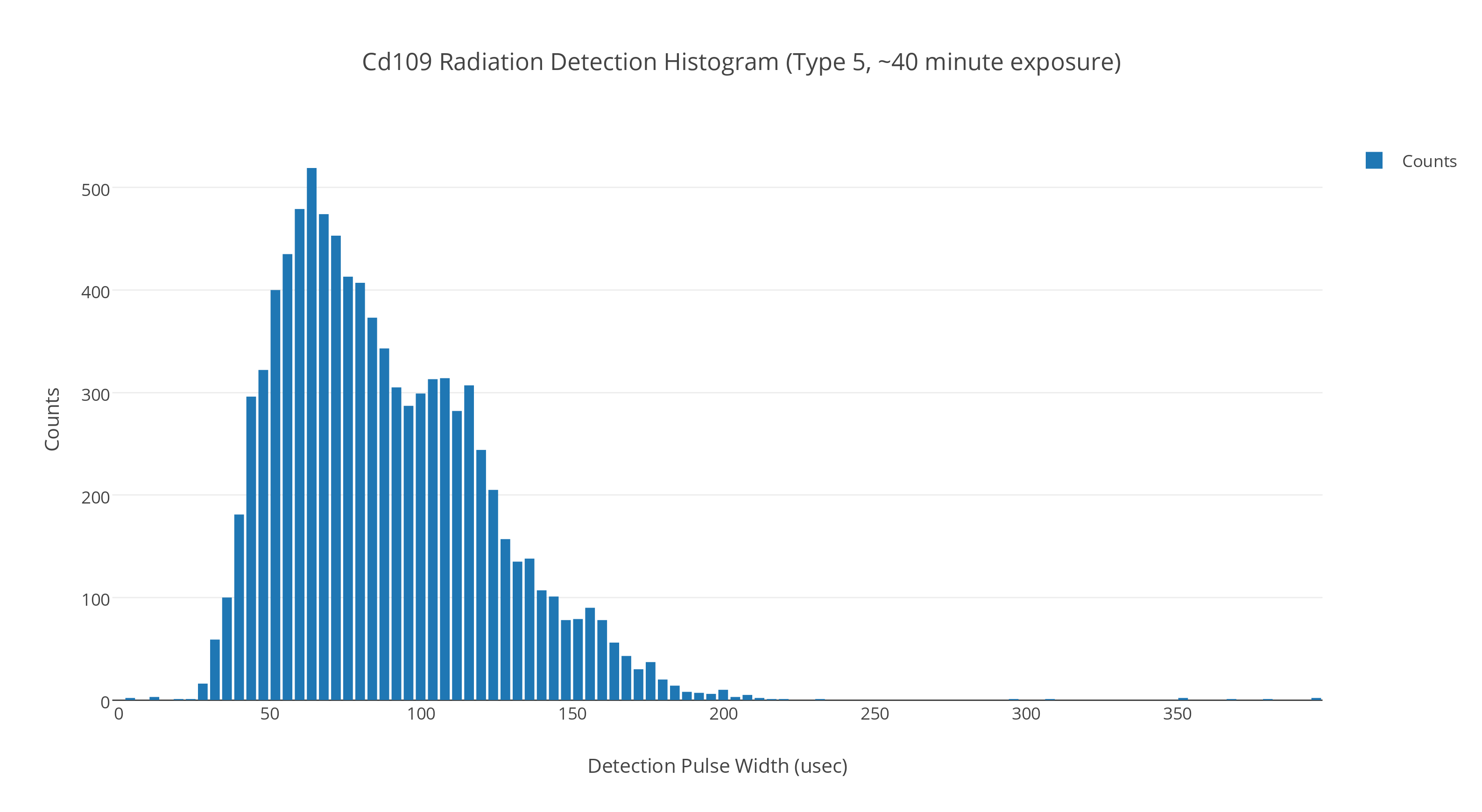
  • X-ray and Gamma Ray Detector: Radiation Watch Type 5
  • Low-resolution thermal camera: Melexis MLX90620 16×4
  • Home-built linear polarimeter: 2x TAOS TSL2561
  • UV: Silicon Labs Si1145
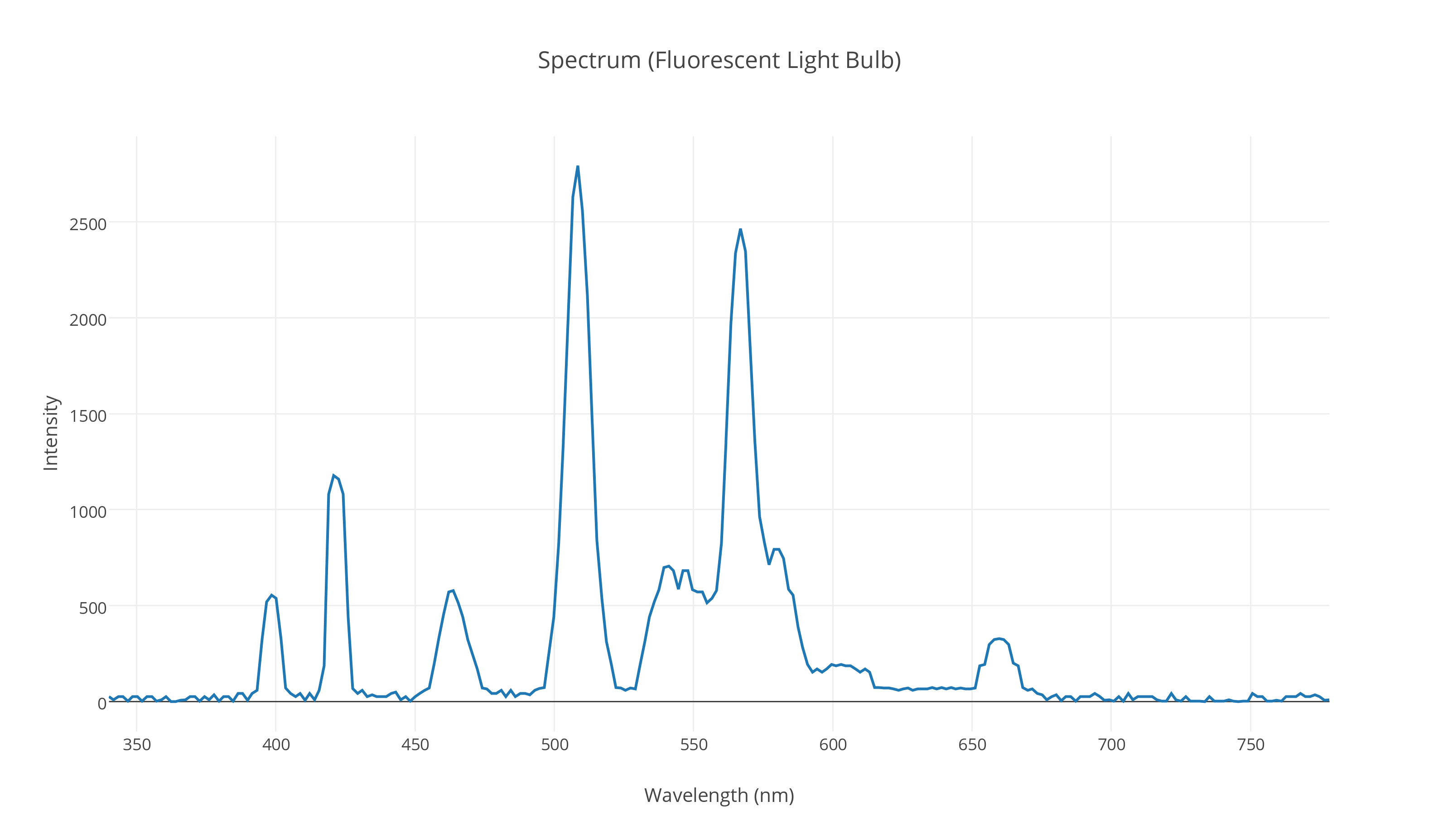
  • Spectrometer: Hamamatsu C12666MA micro-spectrometer, with NeoPixel light source

Spatial Sensors

  • Inertial Measurement Unit: Invensense MPU-9150 9-axis (3-axis accelerometer, gyro, and magnetometer)

Other Sensors

  • Microphone: Analog Devices ADMP401

Check out the project logs for the current build progress, and stay tuned!

GitHub Repository and Source Files

The source files are available on the Arducorder Mini GitHub Repository as the development progresses. The hardware is licensed under Creative Commons By-Attribution Share-Alike 4.0 International, and the firmware and libraries are available under various open licenses. Please see the licenses file included with the source for more information.

Gerbers and Parts List

While the major parts are listed below, the Arducorder is a modular ecosystem of seven boards -- including the motherboard, capacitive touch interface board, and five modular sensor boards. The hardware folder of the Github repository contains the latest Eagle source files, and gerber files that can be uploaded directly to OshPark. While the Eagle files contain internal parts lists, this source directory will also maintain PDFs of schematics and separate parts listings.

Contributions

In addition to the device, this project has developed open source Arduino-compatible libraries for a light weight live tile based graphical user interface, supporting tools, open libraries for new sensors including the Radiation Watch Type 5 and Hamamatsu micro spectrometer, additions to the Adafruit MPR121 library to support capacitive touch wheels, and a port of the Adafruit CC3000 WiFi module to the Chipkit MAX32 platform. I have also greatly expanded the Plotly library for Arduino, which now supports multiple streams, much faster transfer speeds, and sending normal (non-streaming) plots. I have also partially updated the ChipKit IDE I2C and Client/Server libraries to partial...

Read more »

  • 1 × PIC32MX795F512 Microprocessors, Microcontroller
  • 1 × HTU21D Sensors / Temperature, Thermal
  • 1 × BMP180 Sensors / Pressure
  • 1 × MICS6814 Sensors / Gas
  • 1 × HMC5883L Sensors / Hall Effect, Magnetic

View all 31 components

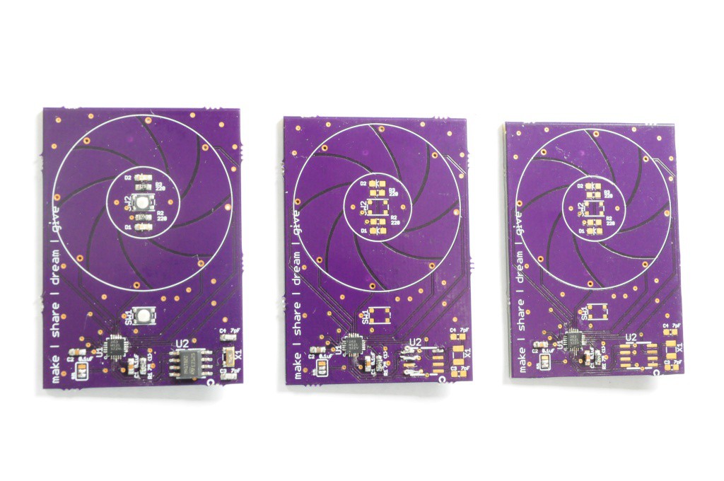
  • And then there were three...

    peter jansen03/10/2015 at 17:47 3 comments

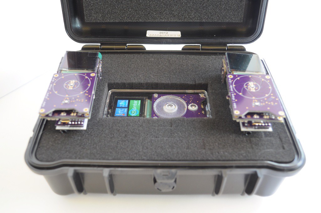
    A quick update -- I was packing up the Arducorder to ship off to @Mike Szczys for the Hackaday Prize booth at SXSW, and thought I'd snap a picture of it fitting snugly in it's new instrument case and shipping enclosure. I hope the folks at SXSW enjoy it, and all the other finalist projects from 2014!

    The other exciting news is that I've /finally/ completed two more Arducorders, with the exception of their enclosures. The original enclosure had some specially machined standoffs inside, and so I'm hoping to put together a slightly modified enclosure with entirely off-the-shelf hardware later this week. Each Arducorder has 7 double-sided PCBs totalling about 200 components, and takes me the equivalent of four full days to assemble (this work is really intended for pick-and-place machines), so it's really incredible to see them when they're finished.

    One of these -- the second one made -- is going to my very excited father, who helped teach me to make, build, solder, and learn from a very young age. I've been tinkering with developing a science tricorder-like device with everything on my sensor wishlist for nearly ten years, and have always said that the second one off the line would be very warmly given to him, as thanks for helping show me the joy of being a scientist, and being a wonderful and supportive dad.

    Developing a complete, modern open source science tricorder-like device has been on my bucket list for a long while, and the Hackaday prize helped me reformulate the project into something tractable enough that it could be designed and built in five months, capable enough that I could include exciting new sensors like micro-spectrometers and high energy particle detectors, and elegant enough that it could make both myself (and, a panel of judges) happy to carry it around in one's pocket. I'm sure like all the other finalists, the last three months were incredibly intense, and between the lab at school and my Arducorder building I was putting in 12 to 16 hour days, every day. I was desperately scared of being knocked out of the competition after the semifinals -- not because I wanted to win, but because I wanted to finish, I knew it would take until the end of October to get there, and I had been pushing myself so hard for so long that I'd likely have collapsed and slept for a week were I knocked out, and lost some steam. I'm extremely grateful that things worked out the way they did, and that the Arducorder is a real, working device that sits on my desk, and has a complete set of plans for folks to build their own, improve upon the design, or use aspects of it for their own projects.

    With the Hackaday Prize 2015 launched today, I'm very excited to see what folks will come up with to help change the world, and make it a better place. I'd like to thank the folks at SupplyFrame for putting this incredible competition together, and helping me make the Arducorder possible.

    Update: More Pictures

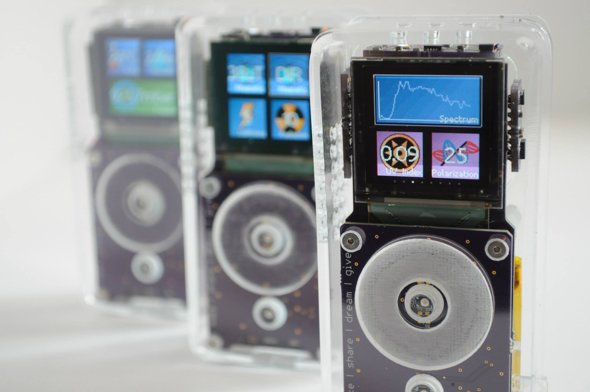
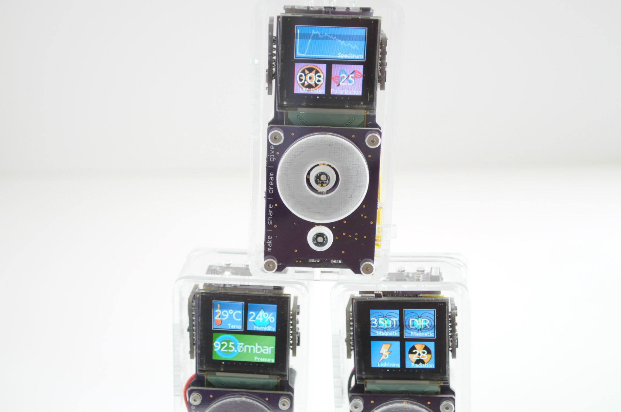
    The first three Arducorders that I've built are complete, and they look beautiful. I'd vastly underestimated the time that it would take me to assemble them -- each unit likely has somewhere around 80 hours in it, which is more than double what I was expecting. For those building their own, don't forget that the driver for the touch wheel has a noise threshold that may need to be calibrated for each unit.

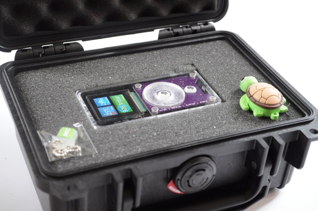
    They fit perfectly into a Pelican 1120 case, which are very compact travel cases with plenty of room for extras, like USB drives with firmware.

    Thanks for reading!

  • Spectrometer Group Buy, and see the Arducorder at CES!

    peter jansen01/07/2015 at 06:37 0 comments

    Just a quick update, and my apologies for taking a while to update -- I think I speak for all the Hackaday prize finalists when I say that the push to finish was absolutely exhausting! In the mean time I've been very busy catching up on writing two papers in the lab, visiting with family over the holidays, taking care of a sick kitty, and trying to find a few hours of rest.

    Arducorder at CES

    The good folks at Hamamatsu have borrowed the Arducorder this week to help demonstrate their beautiful C12666MA micro-spectrometer in action. If you happen to be at CES, be sure to drop by the Hamamatsu booth to check it out!

    Micro-spectrometer Group Buy

    The C12666MA micro-spectrometer is a beautiful instrument, but it's also not the easiest to get ahold of in small quantities. The folks over at Group Buy (who helped get the FLIR Lepton thermal imager out into the community) have a group buy for the micro-spectrometer at the fantastic price of $180, or about $50 off the regular single-quantity pricing. This is a really fantastic deal, and if you've been assembling your own Arducorder (or would like to experiment with the C12666MA micro-spectrometer), it's a great opportunity. As of writing there are only 4 days left to get in on this group by, so you'll likely want to act quickly.

    Power Switch!

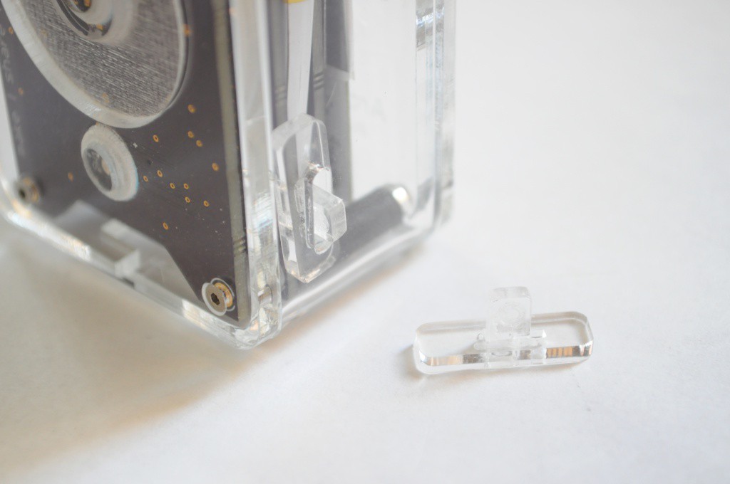
    Every designer has aspects of a project that they do well, and places where they could use a little improvement. Power circuits are where I usually need improvement, and I tend to overengineer them for efficiency so much that occasionally they're simply too complex to work on the first revision. The Arducorder has a very good and high-efficiency buck/boost power circuit, but the case design was missing an important element -- the acrylic slider that covers the power switch, and lets you easily turn the unit on! Free yourself from the bounds of having to carry around a tiny screwdriver or paperclip, and cut out this power switch slider :).

    Just a quick update -- thanks for reading!

  • Project Video, and Plotly data!

    peter jansen10/28/2014 at 06:33 1 comment


    The project video is up! It's been a very busy few weeks building the final revision boards, putting together an enclosure, and adding the final features to the software. I'm absolutely thrilled at the results, and I hope it helps you make little discoveries -- everywhere.

    Connectivity with Plotly

    The Arucorder Mini now interfaces with Plotly -- a website that's like social media for data, that I've absolutely fallen in love with. After hours of rearchitecting the Plotly Arduino library (with Chris from Plotly's help -- thanks Chris!), there is now a beautiful, fast library for Arduino that supports multiple streams, blazing fast transfers, and normal plotting functions. Please use it, and send me links to your amazing streams.

    The Arducorder now supports one touch uploading to Plotly -- you can literally pull the device out of your pocket, and in 20 seconds have sensor data streaming or spectra shared with friends on the other side of the planet. It's really incredible, and I'm pleased with the results.

    The data used in the video is all available on the Arducorder Mini Plotly profile. Here are direct links to some of the data, including:

    In addition, I will try to keep some of the data from the live streams used in the video active, including the atmospheric stream, magnetic field stream, radiation stream, and inertial measurement unit stream.

    Build Instructions and Acrylic Case

    I've tried to put together a case that would help draw people in, while being functional and easy to construct and disassemble for tinkering. Thanks to Connor and David from Xerocraft for helping me figure out the settings for precision laser engraving, and machining the delrin standoffs!

    Thanks to everyone for their kind words and helpful comments over the project! While designing and building the device is very rewarding, I feel like the real fun is just starting -- actually using the device, and having a reconfigurable scientific multitool to explore the world around us.

    I hope you enjoy the video, and thanks for reading!

  • Hardware Revisions -- Preparing for Release

    peter jansen10/11/2014 at 05:47 6 comments

    After a marathon programming session, the different modules of the software came together wonderfully for the prototype video nearly two weeks ago -- it's been very exciting to see the Arducorder Mini hardware coupled with an attractive and intuitive user interface:


    Hardware Errata

    I tend to think of first prototypes as a sketch -- in hardware -- that's as close to the final project as time and experience afford, but with the knowledge that for a sufficiently complex project there will always be an errata, or list of items that need to be modified or corrected in the next revision. The idea here is to make our mistakes cheaply so that everything has the best possible chance of working the first time -- and to ensure that we have enough wiggle room to tinker with any critical bits that don't work the first time, so we can quickly narrow down any design changes for the next revision.

    With PCB turn times taking about two weeks, my recent focus has been revising the few issues that popped up when validating the hardware, and sending these new boards off to be made. It's my hope that if everything validates fine, that these boards will be the first official release candidate for the Arducorder Mini.

    Motherboard

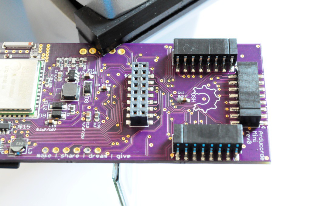
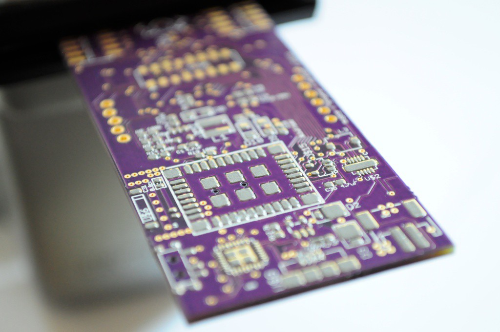
    I confess that when I designed most of the first revision boards, I failed to include mount points on the motherboard and capacitive touch board that would allow the whole thing to be placed in an enclosure! This was a bit of an issue, since the motherboard is only 2-layers, and so densely populated that I had to increase the size a small amount (4mm in both width and height) to accommodate four M2 mounting holes. If I was willing to increase the PCB specifications to 4-layers the board would have been significantly less dense and made mounting much easier, but I'd like to keep the specifications as low as possible so that the boards can be made inexpensively, and the open source community can easily modify the designs with the free version of Eagle CAD. I remember years ago reading that when Stephen Hawking was writing A Brief History of Time, his publisher told him that his readership would be halved for every equation he placed in the book. I feel the same about open hardware -- for every barrier I place on people easily modifying the hardware -- expensive software, 4 layer boards, etc -- that it will reduce the reach by at least an order of magnitude. So I'm trying to keep it simple and accessible.

    Other than mechanical considerations -- the four mounting points, and switching to a connector for the capacitive touch board itself with mounting holes -- there are a few minor schematic changes for the motherboard:

    • Added I2C pullup resistors on motherboard
    • Fixed VCC/GND pin swap on two sets of the PIC32 pins
    • The OLED 13V booster VIN is now sourced from the 3.3V regulator instead of the battery. When sourced from the battery and the booster was disabled, the OLED 13V line would be equal to VBAT, causing a few pixels to stay on, and draining the battery a bit.

    These are largely minor changes, and the technical challenge is largely in rerouting big chunks of an existing board for the modifications.

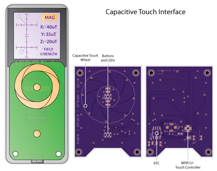
    The capacitive touch wheel board also has largely mechanical modifications to allow it to securely mate with the motherboard, and to mount in a case. The parts have all been moved to the underside of the board (except for the two pushbuttons), leaving a flat surface for some acrylic to mate with for the touch wheel. I'm hoping to have the opportunity to camp out infront of the laser cutter at Xerocraft one evening in the next week or so to design an attractive case with the hardware in hand.

    To help the indicator LEDs for battery charging and programming to shine through to the front face of the enclosure, I've added the small notch along the length of the bottom of the capacitive touch board. Inventables has some back-surface laser-engravable acrylic that looks very interesting, so I've ordered a few pieces and I'm excited to see what some...

    Read more »

  • Tile-based User Interface, and Spectrometer Board!

    peter jansen09/17/2014 at 06:31 1 comment

    User Interface Design

    Visualization and user interface design is a hobby that I really enjoy, and I've been lucky enough to have friends and colleagues who are usability and visualization folks that I've been able to periodically soak information up from.  The open source science tricorders present a really interesting UI problem -- where most mobile devices have at most a few different sensing modalities, here we have 12 different physical sensors, each of which measures between 1 and 3 different things!  What's more, while some of these measurements are single values (like temperature, say 24C), others are vector values (like the three separate 3-axis vectors coming from the MPU9150 -- one vector for acceleration, rotation, and magnetic field strength, giving nine values total, from a single sensor).  In the extreme case, the spectrometer returns a vector of 256 values. That's a lot of data!  I'm really not aware of any other device that comes close to having so many different kinds of sensing data pouring into it constantly, and while this is very exciting, it's also challenging -- we want folks to intuitively browse and navigate through that data very quickly. 

    I've spent the past few weeks researching design concepts for user interfaces by browsing popular design websites, and talking to some friends, and I think I've settled on a very intuitive, attractive, and useful interface design.  I'll confess that I've been working harder, not smarter about this in recent years -- I'd try and design very complicated things that looked like how other people had done mobile devices and visualization (like android phones), which is a fantastic amount of work for a single human being.  Starting this Arducorder mini project almost 4 months ago, and keeping it attractive and capable but tractable has finally helped me work smarter about this, and figure out a lightweight, usable and intuitive interface concept. 

    I like the idea of live tiles.  When done well, it reminds me of Danny Hillis's idea (30 years ago) about maximizing the amount of computing silicon active on a processor at any one time, but attractively applied to data visualization.  Instead of having icons that just take up space and give you a name, here you have tiles that display a live updating value.  This is powerful from a usability perspective -- instead of having to enter each application to obtain this information (which can consume a lot of time), the most important information is available at a glance from many applications.  While this has largely been applied to communication (e.g. messaging), web (weather/news), and I'm sure sensing applications, here we're going to construct an interface  made almost entirely of sensor data. 

    The really interesting aspect (if you're a data abstraction nerd, like me) is that if we consider only this special case -- visualizing sensor data through tiles -- then we can formulate the software engineering aspect of this very elegantly.  If each tile has a sensor data buffer behind it, then we can browse it's most recent data on the top of the tile, then activate the tile to display additional (historical) data and different visualizations.  If we abstract the sensor data buffer into a few different types, like continuous streaming data (from something like a temperature sensor or an accelerometer) and discretely sampled data (from something like a lightning sensor, that only activates when an event occurs), then we can get rid of the idea of an application.  The design concept becomes browsing sensor data buffers first through a high-level tile interface, and then activating an individual buffer and using a suite of generic visualization tools to better explore it. 

    Interface Implementation

    All of the software engineering aside, what the user sees is very attractive -- tiles with live data that they can browse through very quickly with...

    Read more »

  • Spectrometer Board Design, and Beginning User Interface

    peter jansen09/04/2014 at 02:41 0 comments

    A quick update with lots of progress designing the spectrometer (and thermal camera) board, attaching the radiation sensor board, and beginning to work on the low-level routines for the user interface!

    Fast and Efficient Bitmap Rendering

    Now that much of the hardware is in good shape (or being fabbed), I've been working on the low-level software and APIs that would support building an intuitive and attractive user interface. 

    A bit of background -- from my hobby of indie game development in undergrad and participating in the Ludum Dare 48-hour game competitions (a really fun experience!), I've picked up that in a desktop system (and some embedded systems), a graphical user interface is often functionally implemented as a large collection of bitmaps stacked atop each other with transparent layers.  This has the benefit of being able to make large changes to the user interface through editing configuration files that describe which bitmap corresponds to which background or widget or font (instead of recompiling code), and also allows the user interface artist to easily use whatever tools they're most comfortable illustrating in to rapidly iterate without having to use middleware, or (even worse) be constrained to building an interface entirely out of low-level graphics primitives like squares, ellipses, and triangles.

    This is the approach that I'd initially planned on using, but I'd discovered about a month ago when running a display verification test that the ChipKit SD card library has a read speed of around 100k/sec, which puts the time to load and display a bitmap on the order of about one second -- far too slow for an interface.  There are faster libraries like sdfat, but these required more than a solid evening of porting, and at some point you have to put these on the wishlist, accept the constraints, and exploit the benefits of your existing system while architecting it in such a way that you could drop more advanced functionality in later with a minimum of effort. 

    Posterizer Tool

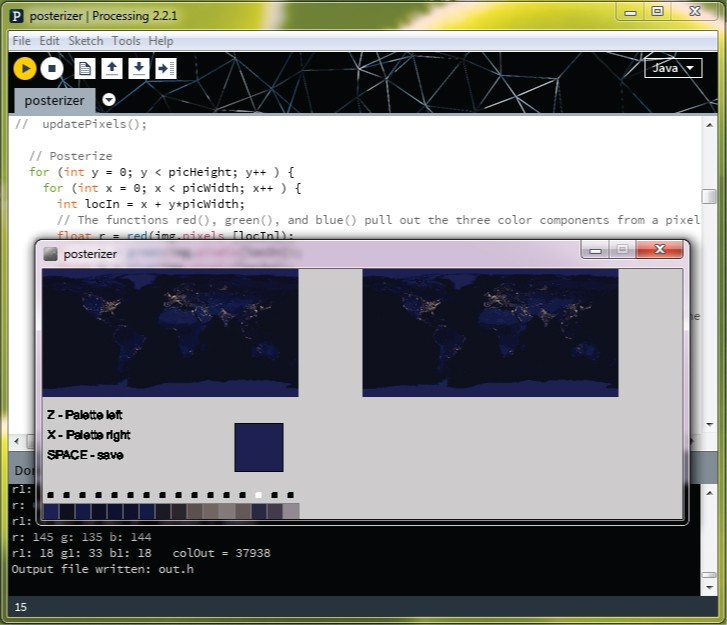
    While loading bitmaps from an SD card is currently slow, the PIC32MX processor that the Chipkit Max32 uses does have 512k of flash memory that (in addition to code) can store bitmaps that can be loaded very quickly.  A full screen (128x128) 16-bit (2bpp) bitmap takes 32k of memory, so we can't fit very many in memory, but if we manage our resources and store things efficiently, we should have plenty of space for backgrounds and widgets and icons in ~128k or so. 

    One way of compressing bitmaps is to reduce the colour depth -- if we can reduce an image from 16-bit colour (64k colours) to 8-bit (256 colours) or 4-bit colour (16 colours), then we can store the image in half to a quarter of the space.  The trick is selecting a smaller colour palette so that the final "posterized" image still looks very good. 

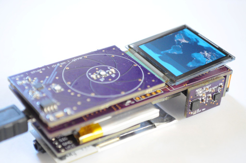
    There are automated algorithms to do this, but they often give non-ideal results, and I want this thing to look /good/.  I've been looking at user interface concept art the last few days to get ideas, and I'd had the idea of having a main menu that showcases a space theme by having a scrolling background under an icon-based main menu with multiple pages of icons, similar to Android.  I grabbed a copy of NASA's amazing public "earth at night" photograph, downsampled it to 256x128, and used manual posterizing tool I quickly put together in Processing to reduce the colour depth to 4-bit, and store the image as a static array in flash.  Despite being 256x128, the image only uses 16k of flash, and the manual conversion (above) is so good compared to an automated algorithm that I would never have known it was poserized if I didn't do it myself!  It also scrolls back and forth at about 50fps, which looks really impressive.  While I'm still deciding the final user interface concept, it was a good test, and a useful tool to compress the graphic assets into flash so that they're...

    Read more »

  • Update: Now with 100% more WiFi!

    peter jansen08/27/2014 at 06:41 2 comments

    A quick update, with some of the high-risk high-gain aspects of the project!

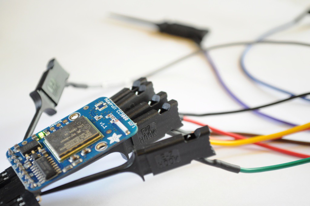
    CC3000 WiFi Module and ChipKit Library Port

    It's great to get out of your comfort zone and learn new skills or expand your familiarity with different aspects of design.  For me, in addition to the capacitive touch wheel, I decided to include the popular CC3000 WiFi module from Texas Instruments.  I think connectivity fits a lot of the use cases for a science tricorder-like device, from kids using social media to share their sensing and measurements to engage themselves and their friends, to nerdy scientists that spend their entire days in the lab (like me) who would like to push all their raw data to somewhere like data.sparkfun.com for sharing, advanced visualization, or later analysis.  Personally, a neat visualization experiment I'd like to try is to sit the Arducorder Mini on my desk for an afternoon when we're expecting a storm, and visualize the storm coming in through data -- the decreasing temperature and pressure, increasing humidity, reducing distance-to-lighting, and it'd be neat to see if any x-rays from close lightning strikes are detectable and coincide with the lightning detection.  

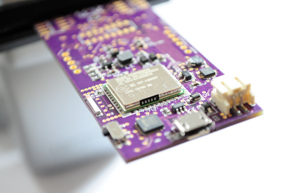
    This is my first use of a WiFi module in a project, and so my concerns in terms of hardware were routing the antenna traces correctly, and being able to successfully interface with the module using an open library.  There are a number of open reference designs for the CC3000 antenna circuit, and space being at a premium I ended up using the same layout as the folks who designed the open Spark Core (thanks Spark team!).  In terms of open ilbraries, Adafruit released their CC3000 Library, which was recently ported to the Due, which would give me a trail of github commits to look through when porting to the ChipKit MAX32-based system that the Arducorder Mini is based upon.  It all looked good, so I incorporated the CC3000 module into the Arducorder Mini motherboard.

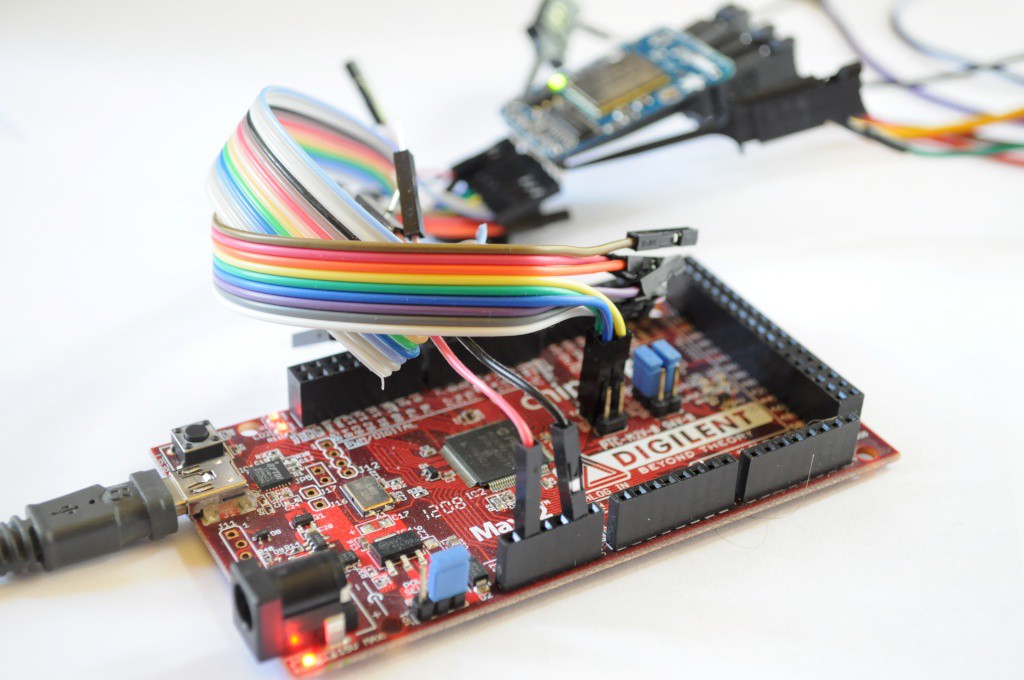
    To make a bit of a long story short, I ran into a problem similar to the issue with the capacitive touch sensor requiring the ChipKit I2C library to be updated from the Arduino 0023 libraries to the new Arduino 1.x (post-Due) libraries, to make use of the additional features that have been added in the last few years.  With the capacitive touch sensor, it was fairly easy to add the repeated stop condition support from the newer Arduino 1.x I2C/Two-Wire libraries, but the Adafruit CC3000 library is based on the much larger Arduino 1.x ethernet library, so there was a good deal of effort involved -- porting the Adafruit CC3000 library from the AVR/Due to the PIC32 from the top, while simultaneously updating the ChipKit Arduino peripheral libraries from the bottom.

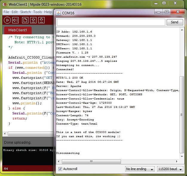
    Fully updating the ChipKit libraries to Arduino 1.x would be a full-time task for someone familiar with their inner workings for a good week or two, so it's well beyond the scope of this project -- but after a solid weekend of work I was able to successfully port enough of the Arduino 1.x ethernet library (and its dependencies) to then port the Adafruit CC3000 library to the ChipKit!  The picture above shows success, and the Arducorder Mini successfully fetching its first webpage and displaying it over the serial console.  Great stuff!

    In the end, this means that in order to compile the Arducorer Mini firmware, I'll also have to maintain an updated version of the MPIDE on the github repository.  A side effect of this will be that Chipkit folks should be able to enjoy the benefit of some (partial) Arduino 1.x compatibility.  

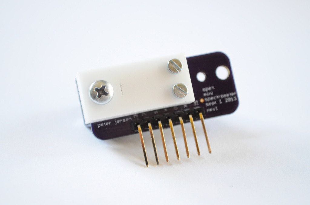
    Open Mini Spectrometer 

    In addition to the WiFi module, the other high-risk high-gain aspect of the Arducorder Mini is creating a new version of the open mini spectrometer suitable for one of the low-profile modular sensor boards.  I really needed to build (and not code) last weekend, and have been boring...

    Read more »

  • Quick Update: Capacitive Touch Wheel!

    peter jansen08/12/2014 at 03:31 3 comments

    A quick update -- the capacitive touch wheel is working great!

    I've been working through verifying the hardware (since there's a lot of it), and ensuring all the critical hardware bits are working before shifting focus to the software and user interface.  This is largely to make my mistakes cheaply -- it takes two weeks for new sets of boards to arrive, so it's important to figure out any issues sooner rather than later so that they can be sent out for another turn.

    The capacitive touch board was one of the first of the half-dozen modular Arducorder Mini boards that I assembled, and one that I've been excited to get working -- it's the first capacitive touch sensor that I've designed.  I mentioned that in an earlier post I'd had trouble contacting the MPR121 capacitive touch sensor on these boards, even after putting together several capacitive touch boards (with progressively less of the board populated, to try and isolate the issue):

    Making expensive (in terms of time) mistakes

    My normal debug process is to try and isolate the problem -- first to determine if it's a hardware or software issue, then narrow it down to figure out what's going on.  Eagle footprints -- check.  Schematic verified -- check.  Three boards, three different MPR121 Arduino libraries, and one touch board jumpered to an Arduino Due later, the MPR121 still didn't appear to be communicating (while the real time clock on the same board seemed to be communicating fine).  This is a really unusual problem, and I'd convinced myself that as unlikely as it was, it was possible that the MPR121 chips had simply arrived dead, or that they were particularly heat sensitive and not amenable to being reflowed in a toaster oven (although the one I hand soldered made this last alternative less likely). 

    To test this I ordered more touch boards (with slight revisions) from OSHPark, more MPR121 ICs from a different supplier, and an MPR121 breakout board from Sparkfun.  The boards arrived this past weekend, and I put one together with the new parts -- same issue, it didn't communicate.  I wired up the Sparkfun MPR121 breakout, and tried three MPR121 libraries (I2CDev, Sparkfun, and Adafruit, who just released one and a breakout to match) and two boards (Chipkit Max32 and Arduino Due) -- same issue.  It's extremely unlikely that parts from two different batches would be bad, and the Sparkfun breakout board should be tested during assembly -- What was going on?

    For debugging purposes, I decided to try the same code and wiring on an Arduino Uno, not because I had any reason to expect that it'd be different, but just to see -- being their flagship product, it was likely it'd work, and maybe there was something subtly different with the timings. And it did work!  On goes the logic analyzer to see what's going on!

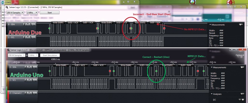
    The MPR121 communicates over I2C, which is a two wire master/slave protocol with a bidirectional data line (SDA) and a clock line (SCL) that's clocked from the master.  Above we see the waveforms for the first communication to the MPR121 using the Adafruit library, with the Due on the top, and the Uno on the bottom.  The interesting thing is that the waveforms are nearly identical, and in both cases the MPR121 is acknowledging the communications by sending the ACK bit at the end of each transfer, but in the case of the Due (and Chipkit), the read commands are not returning data. 

    There is one notable difference in the waveforms for the Due and Uno -- during the command to read data from the MPR121, the Uno is correctly sending an I2C "Repeated Start" condition between telling the device it wants to read and actually performing the read, where as the Due is instead sending an I2C "End" followed by a "Start".  In most cases that I've encountered this doesn't appear to be an issue, but the MPR121 datasheet clearly appears to show a "Repeated Start" condition for this transaction, so it's likely...

    Read more »

  • Sensor Board Mega-Update!

    peter jansen07/29/2014 at 06:14 4 comments

    A big update with lots of pictures -- I've been building and testing many of the first revision sensor boards.

    Watching the PWM of your soldering station's power supply!

    One of the things I remember most from building the Open Source Science Tricorder Mark 1 is that the moment I had it built and programmed -- around 2am, late one weekend, doing laundry at my parents house in the finest grad student tradition -- I immediately looked around for things to sense.  The magnetometer visualization on the Mark 1 was always my favorite, and holding the Mark 1 up to a wall-mount power supply I was able to see the fields of the transformer bouncing back and forth, only moments after finishing the device.  Definitely very cool, and very memorable.  Years later we were hunting down some high magnetic fields in a mens washroom under an NMR lab at school, which is probably the second most memorable (and probably one of the most hilarious) moments of science I've had. 

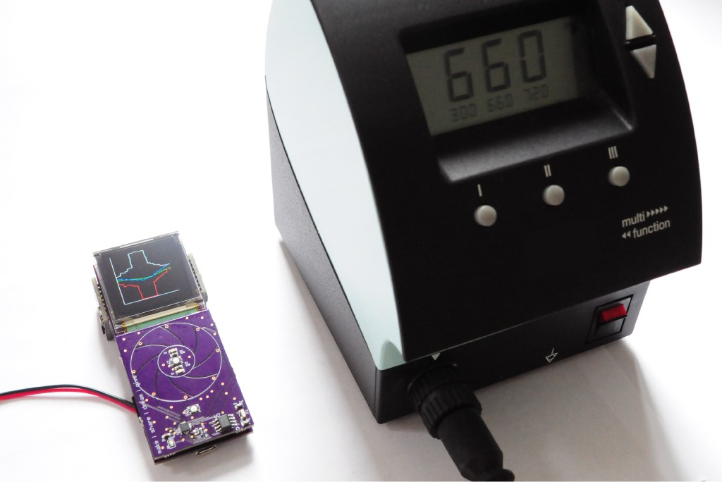
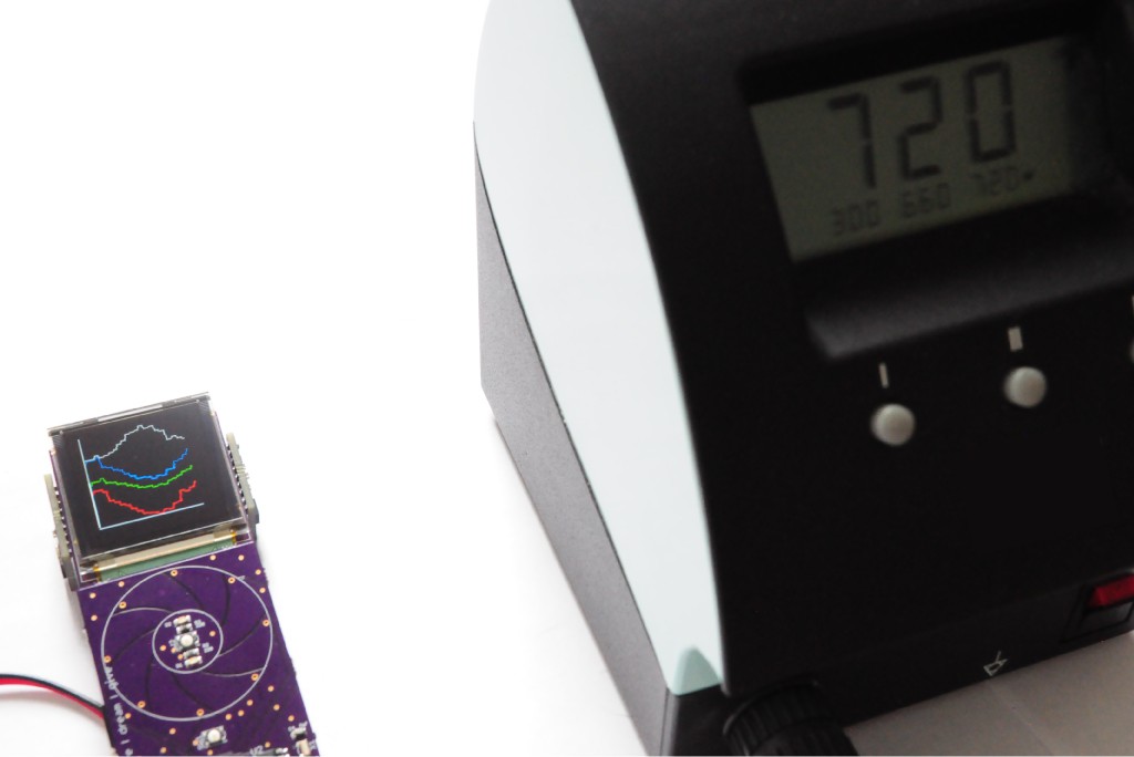
    I decided that, with many of the Arducorder Mini sensor boards up and running, and a basic multi-series graph visualization plotting the x, y, z (RGB) and total (white) field strengths from the magnetometer, that it'd be interesting to place it near my heavy soldering station -- heavy from a big transformer in its base -- and see what we could see.

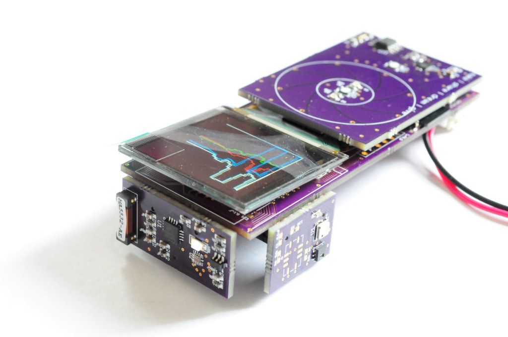
    The solder station works by pulsing the heater on the soldering iron to keep it at a set temperature.  When the internal temperature sensor reads the iron is too cold, it likely pours on the juice to keep it at a given temperature.  The neat thing is that this appears to happen in discrete chunks of time a second or two apart -- looking at these two pictures, we can see a roughly sinusoidal magnetic field strength (white line) from the transformer -- my first guess is that this is that this is the 60Hz line frequency aliased by whatever the sampling frequency is of the magnetometer here (about 20Hz).  But, in the first picture, something really interesting is visible -- the field strength suddenly shoots up for half a second, likely signifying that the soldering station has engaged the heater on the iron.  Very neat to watch!

    And here's a quick video I took while testing the magnetometer (and microphone -- the purple series). 

    Modular Sensor Boards

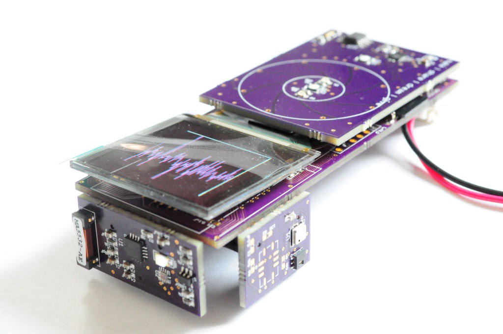
    I try to make my mistakes cheaply, so recently I've been building as many of the first-revision boards to verify their functionality, and note any issues or modifications for the next revision.  Pictured here (above) is the sensor board that contains the lightning, UV, and audio sensors (front), and the atmospheric sensor board that contains the atmospheric sensors like temperature, pressure, and humidity (right).  

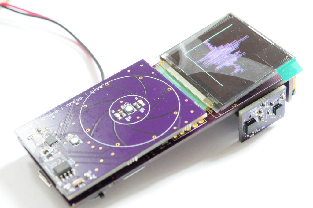
    The same view, but here I've just waved a pair of piers that are slightly magnetic near the Arducorder Mini to show the simple multi-series graph widget.  There's still a great deal to do on this widget, but it's a good start for easily graphing a few related sets of data, and the autoscaling feature means it's entirely hands free. 

    To verify the functionality of the microphone, I wrote something that would pipe the data to a graph, and started singing to watch the waveforms.  (Actually, the first thing I did was to put on some music with a beat, put the Arducorder Mini up to the speaker, and see if I could watch both the audio waveform and the magnetic field from the speaker, but I think I'd have to look at the data a little closer or plot it overtop of each other to verify that the field strength changes were correlated with the audio amplitude).  Still, very cool for something that's just starting!

    The UV sensor also looks to be communicating okay, and the data changes when I place my hand over it, but it'll need a bit more work to verify the measurements.  I didn't happen to have a storm handy to test the lightning sensor, but the breakout board I have seems to be particularly good at...

    Read more »

  • First Sensor Boards

    peter jansen07/16/2014 at 06:42 5 comments

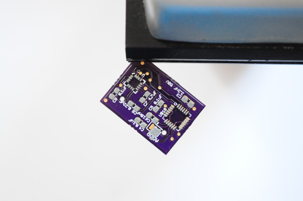
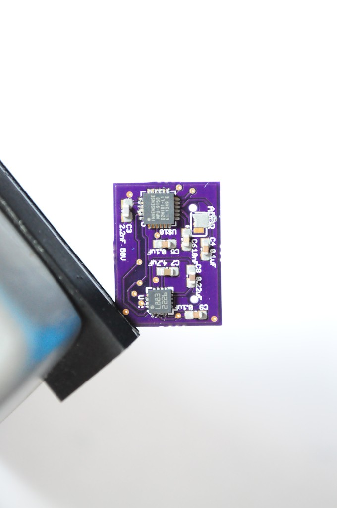
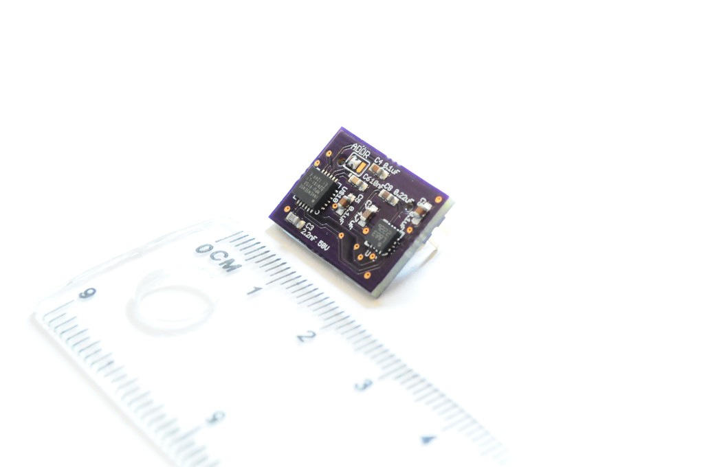
    A bunch of the sensor boards arrived this week!  I confess that holding them in your hand is a lot different than seeing them in Eagle CAD -- these new sensor boards are tiny. 

    Modular Sensor Boards

    The first three (of five) sensor boards arrived, with the radiation sensor board (and the touch interface board) arriving a few days later.  The spectrometer board is the only sensor board that still has to be designed, and I'm waiting on laying it out until I have a better idea of how the radiation sensor board fits on the back.  The spectrometer is the largest sensor in the device, but if there's room I might be able to lay it down and make the entire device even thinner -- definitely worth holding off a few weeks on.

    The first thing that struck me is that these sensor boards are *tiny* -- much smaller than any of my previous boards.  They're about the size of the tip of my finger!  I think the idea of utilizing as much real estate on the outside of the device as possible for sensors (rather than just having them all face towards the front) is really a fantastic design idea for keeping the device small. 

    These boards are so tiny that they're a bit of a challenge to attach a solder stencil to. Since invariably many of the parts I use end up having very fine pitches (0.4 to 0.5mm), my favorite method of stenciling is to clamp the board and stencil in a clamp, adjust it so it's aligned, then squeegee on some solder paste.

    Here, the sensor board combining the Honeywell HMC5883L 3-axis magnetometer (left) and the Invensense MPU9150 9-axis accelerometer/gyro/magnetometer (right) is being assembled.

    Here's the board, with solder paste.  Looks good!  The paste on the MPU9150 is a little misaligned by a few tenths of a millimeter, but it tends to sort itself out during the reflow process.  I usually adjust some of the more worrisome looking misaligned paste around with a pair of tweezers before placing the components.

    Here's the board with paste and after the components have been placed.  Time for reflow!

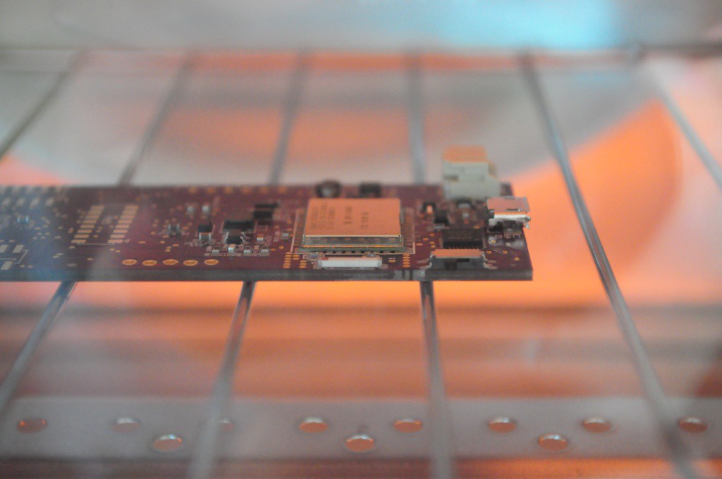
    I tend to reflow most of my boards in a $20 toaster oven.  It sounds crazy the first time you hear it, and you feel crazy the first time you do it, but it usually works out very well.  Sparkfun has a tutorial on converting toaster ovens into reflow ovens, but I live a little more dangerously and just set the heat to maximum and bake -- watching the board like a hawk until it reflows, and then popping it out of the oven immediately after.  

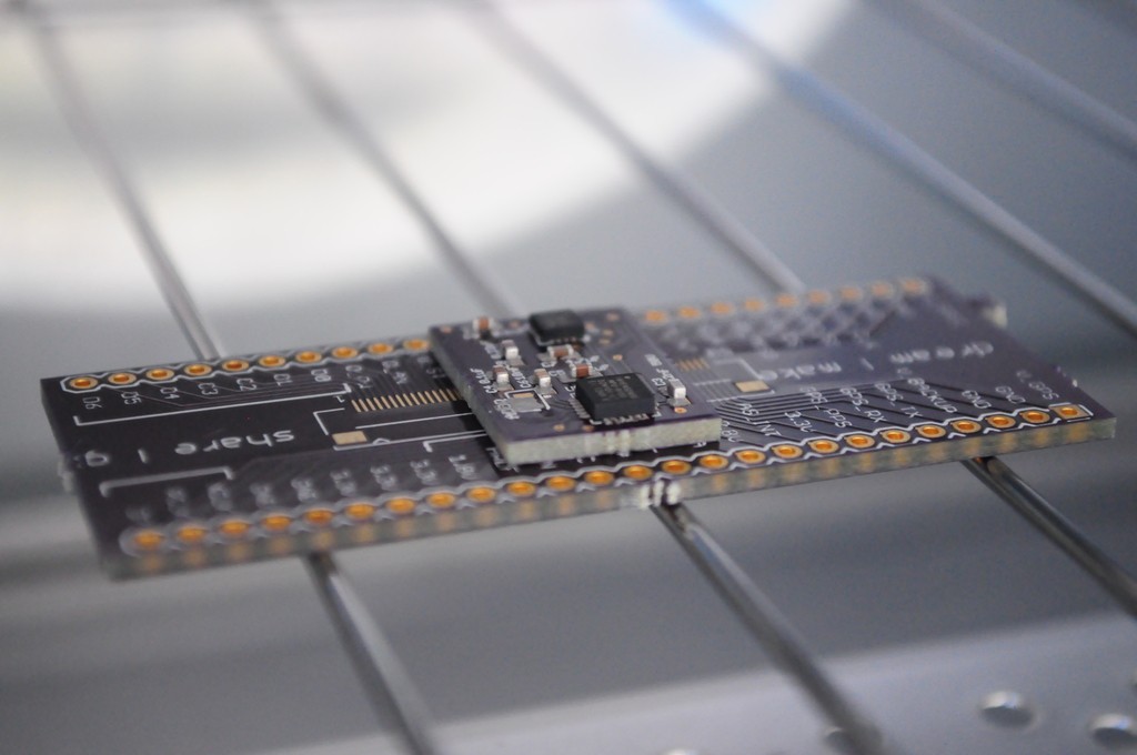
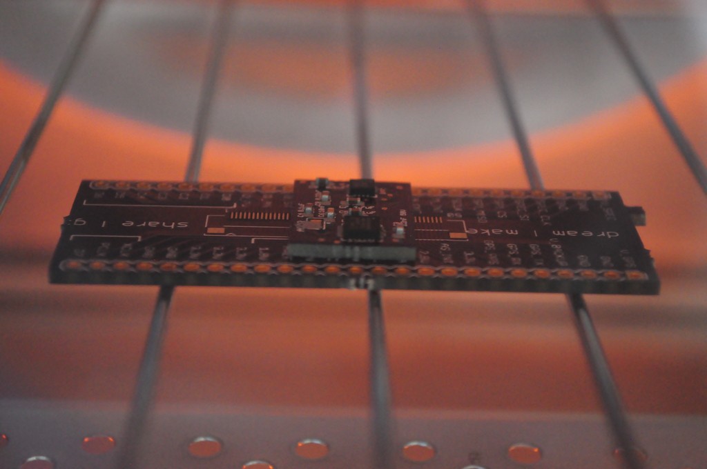
    These sensor boards are /so small/ that they will fall through the grill of the toaster oven, so I've layed this one on an old coaster -- er -- breakout board from another project.  I'm also trying not to snap pictures for too long, since I have to pull it out as soon as it reflows or the parts will cook!

    The finished magnetometer and inertial measurement unit sensor board.  Not shown was attaching the sensor board connector to the back of the board -- a 20 pin double-row 2mm-pitch male connector. 

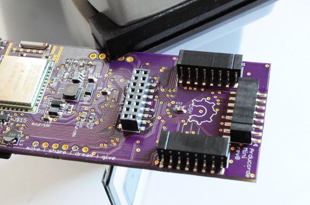
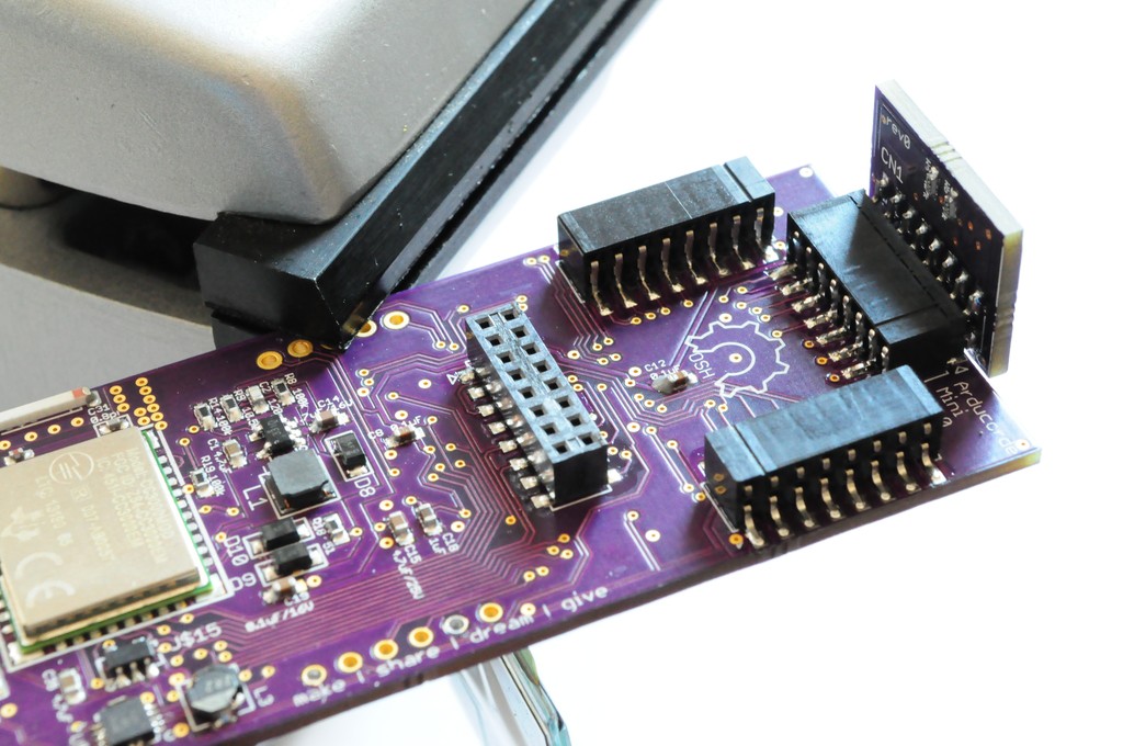
    I hadn't yet soldered on the sensor board connectors to the motherboard, in part because they were low on stock, so I could only order enough for a few boards. These have alignment pins that go through the board (and make routing a little more challenging), but it's worth it -- they align in exactly the correct, orthogonal orientations. 

    I confess that one of my largest anxieties about this design was the sensor board connectors.  I literally looked through thousands of connectors on Digikey searching for one that was both right-angle, board-to-board, medium-density, strong enough to firmly mechanically support the sensor boards, and larger than a 0.5mm pitch for easy alignment and soldering. There were not many options.  The ones I settled on looked like they would have /exactly/ the right mechanical clearance if the board could be routed within 10 mil of the connector footprint, which is a little tight...

    Read more »

View all 16 project logs

  • 1
    Step 1

    Step 1: Motherboard Assembly and Programming

    I designed all of the boards to be hand solder friendly, with leadless QFNs all on one side (that can be reflowed). If the other side has components, these are usually larger and easier to hand solder.

    Step 1 is to use your stencil to apply paste to the CC3000 side of the motherboard. Note that we'll occasionally switch between Revision 0 and Revision 1 motherboard pictures, but you should be using revision 1 (or the latest release, if a later revision exists at the time of reading).

    Populate the back components. I recommend leaving off the sensor headers until the end -- it'll make it easier for the board to fit into a holder while you solder the top components later.

    Reflow the bottom side. You may wish to pre-solder at least the mechanical mount points on the USB connector and battery connector to make sure they don't move (and end up angled) during reflow.

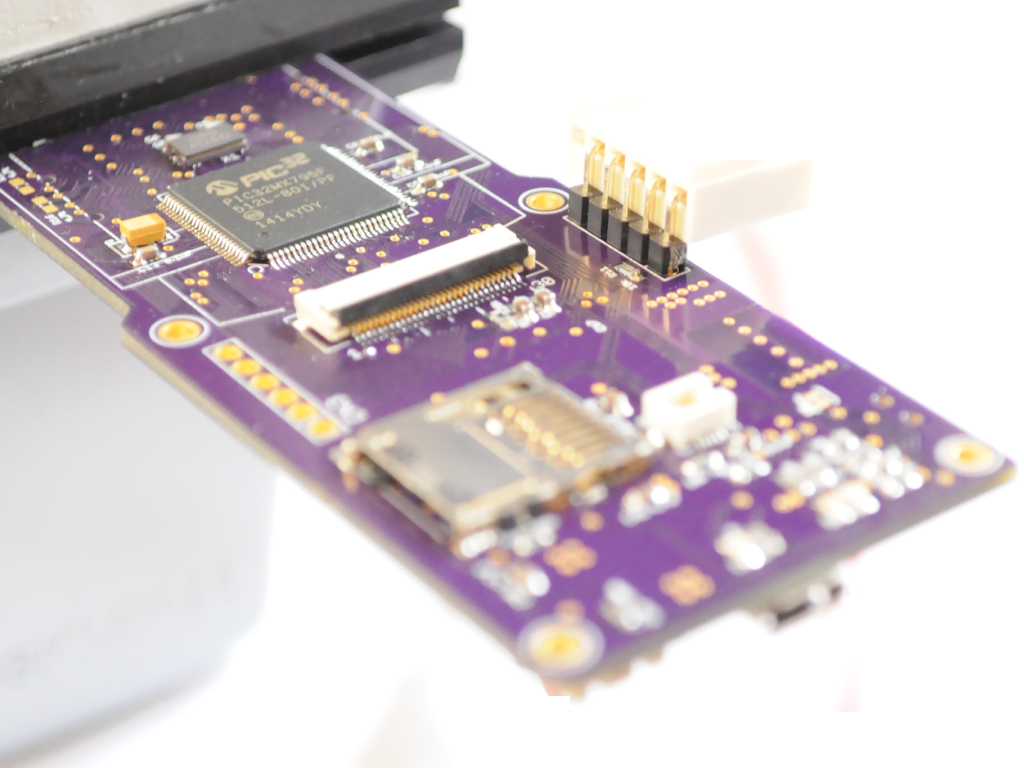
    Next, solder the top components. I do this by hand, starting with the PIC32, moving to the OLED connector, and then if everything looks good, stenciling the bottom of the board for the passives. Please take your time, it's not a race -- and if you bridge the connections it will make a mess of the board to clean up. For reference it takes me about an hour to solder all four sides of the PIC32, going slowly with very small amounts of solder paste. The OLED connector is similarly fine pitched, and the capacitive touch wheel connector is VERY fine pitched, so take it slow. The crystal will require a quick reflow with a hot air station to be properly hand soldered.

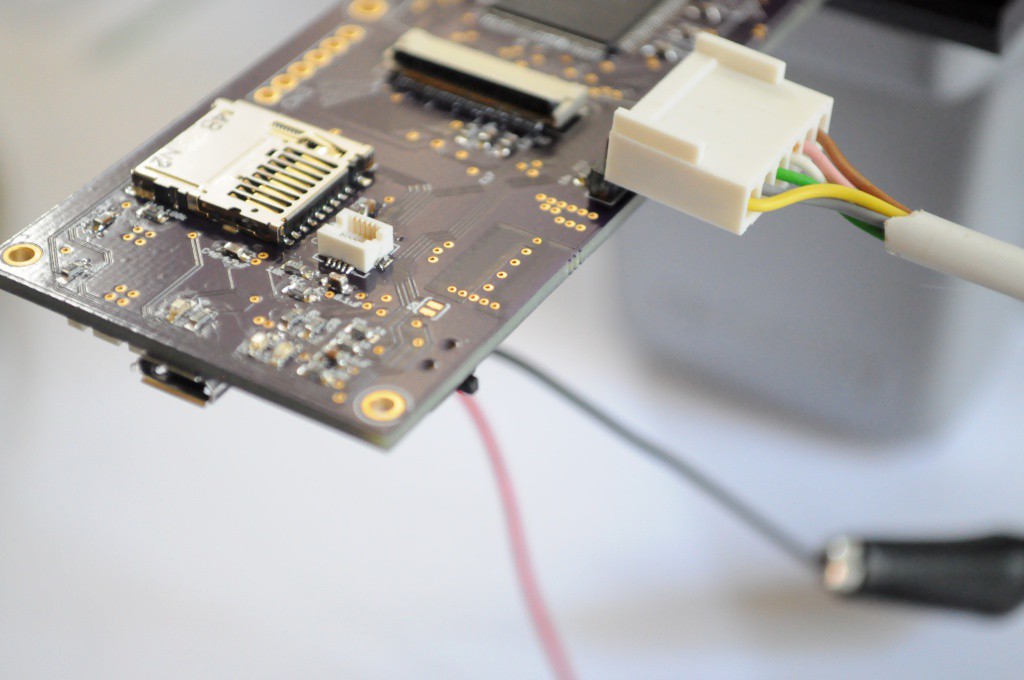
    Do not solder on the programming (ICD3) connector -- This is a one-time use connector, so the pins are offset such that the tension will let you quickly program the device, then remove the header so it's not in the way.

    Firmware

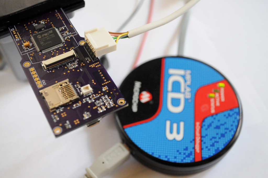
    Next we'll need to load the Chipkit bootloader onto the Arducorder Mini motherboard using a Microchip PIC programmer, like this ICD3. If you're not a PIC developer and don't need the debugger functionality, Microchip also has a programmer that's about a tenth of the cost, and here we're just using it to upload the bootloader -- afterwards we'll be uploading firmware using the Chipkit IDE over USB.

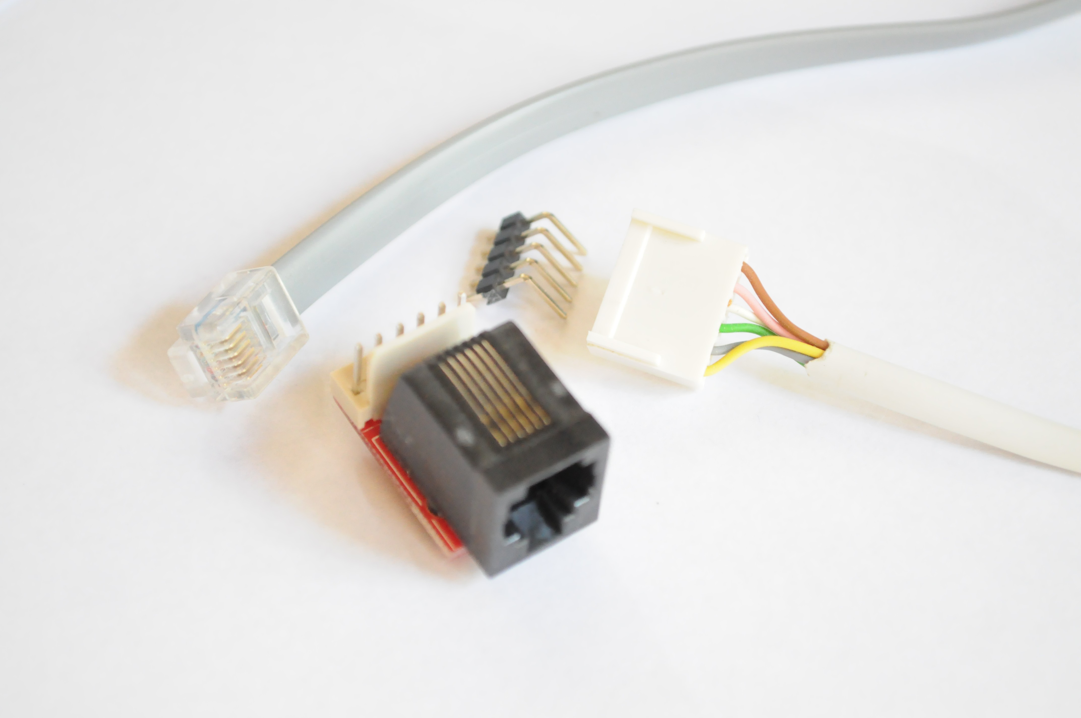
    If you're using the ICD3, you'll need a converter to go from the 6-pin phone connector to a regular 0.1" header (Sparkfun sells these). Note that only 5 pins are exposed on the motherboard -- the unused pin (opposite of MCLR) isn't included since space is at a premium.

    Don't forget to power the board from an external supply through the battery connector -- 3.3V from a regulated supply should to well. Ensure that you check for bridges before powering the board, and are using a power supply with a fuse and current meter so that it doesn't blow the whole thing to the moon if you've got a solder bridge.

    The Chipkit folks maintain a great set of documents on how to go about this process (which only takes a few minutes), as well as having the bootloader that you'll need to install:

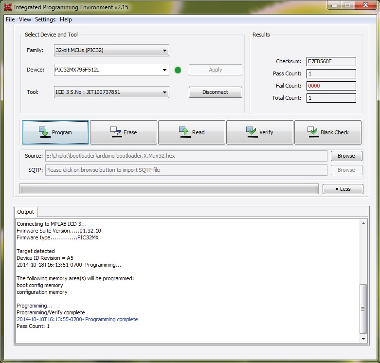
    The abridged version is that in the new Microchip IDE this has been made super easy, and takes only a few clicks with their HEX programmer:

    Connect, Select bootloader, Program. If you see something like this output, then congratulations, the programmer can successfully commuicate with the PIC32 and has programmed the bootloader! If you don't see 'Target Detected', ensure that you've powered the board externally, and that the power switch is in the "ON" position. If those are the case, verify your soldering.

    CC3000 Firmware Update

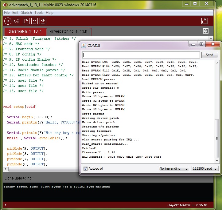
    The Adafruit CC3000 library requires that the firmware on the CC3000 is updated in order to connect. This is a quick update and a good first test. Unconnect the programmer and connect a USB cable. Using the Chipkit IDE (Ideally version 0024 or later), load the driver patch sketch and allow it to update the CC3000 module firmware. You shouldn't require the Arducorder-modified Chipkit IDE (which updates a few of the libraries for better Arduino 1.x compatibility) for this operation.

    Finishing up soldering

    Now that everything's working, feel free to solder on the sensor board connectors:

    If you're eager to see /something/ on the screen, you can grab the latest Arducorder firmware (currently "test2k") as well as the updated Chipkit IDE (skip ahead to the main firmware step for the link). You will likely see something on the screen before it fails to find the sensor boards or capacitive touch wheel attached, and freezes -- but this will let you know that the screen is healthy and functioning.

    Congratulations! You now have a working Arducorder Mini motherboard! On to building the sensor boards.

  • 2
    Step 2

    Step 2: Sensor Boards

    Congratulations -- if you've successfully soldered the motherboard, then you'll likely have little issue putting together the sensor boards. They're very tiny, and about a 2 hour build per board. Because the process is similar for each board, here we'll just highlight any deviations to keep in mind. All of these boards have been designed to be relatively easy for an experienced surface mount solderer to put together -- one side has most of the parts and can be easily reflowed, and then the other side (usually just a connector, and perhaps a few passives) can be quickly hand soldered.

    The six sensor boards are: (1) the capacitive touch board, (2) the magnetometer/IMU board, (3) the atmospheric board, (4) the lightning sensor board, (5) the spectrometer/thermal camera board, and (6) the radiation sensor board. Of these, only the spectrometer board and radiation sensor board have special instructions.

    Spectrometer Board

    The spectrometer/thermal camera board houses the most high value sensors on the entire device, and individually represents most of the BOM. Ensure that you take care when assembling this board, and verify the voltages (both 3.3V and the 5V boost for the Hamamatsu micro spectrometer) before soldering the thermal camera and spectrometer.

    I very strongly recommend placing squares of kapton tape (or another non-conductive tape) under both the spectrometer and thermal camera before soldering. Their cans are conductive, and this will help avoid any of the other pins accidentally bridging with the case.

    Optional light source header: The spectometer board includes an optional 3 pin header for connecting your own light source. This header exposes 3.3v, GND, and an I/O pin. It's recommended that you solder a connector to this header, that you can attach LED boards to. The I/O pin should be used to drive a MOSFET that powers the LED -- the pin itself shouldn't be used to source any current (especially for something like a small incandescent bulb!)

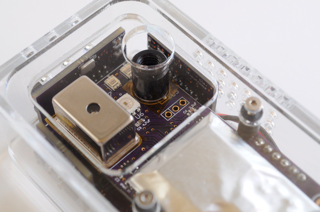
    Filters: The two light sensors at the top right of the board have mount holes on either side. These are designed to allow user-configurable narrow band filters (or polarization filters) to attach, for user configurted applications. You'll need to laser cut or 3D print a tiny holder for your filters that affixes to this footprint, with M2 machine screws.

    Radiation Sensor Board

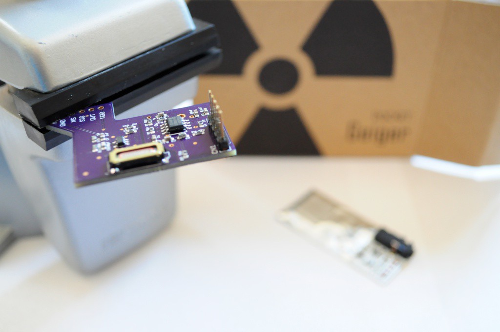
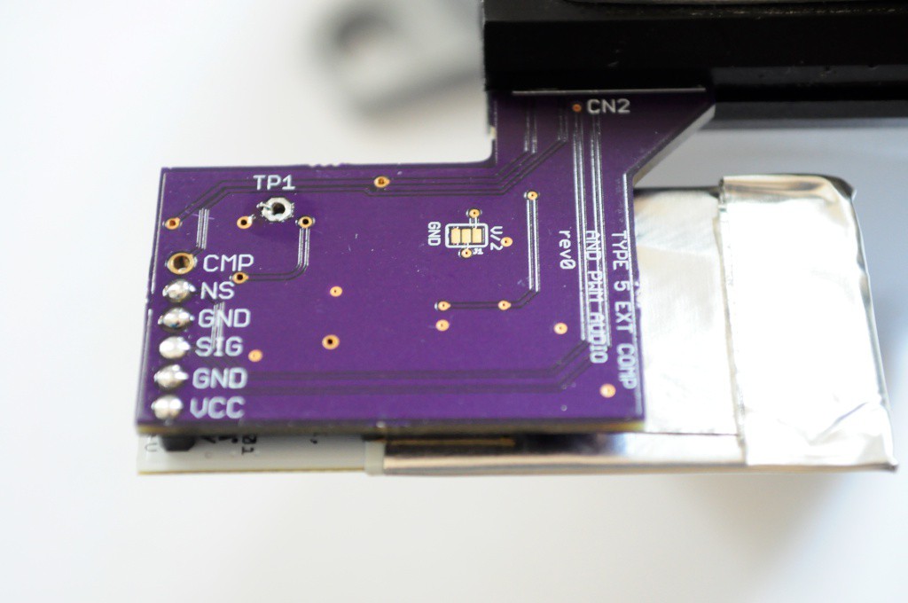
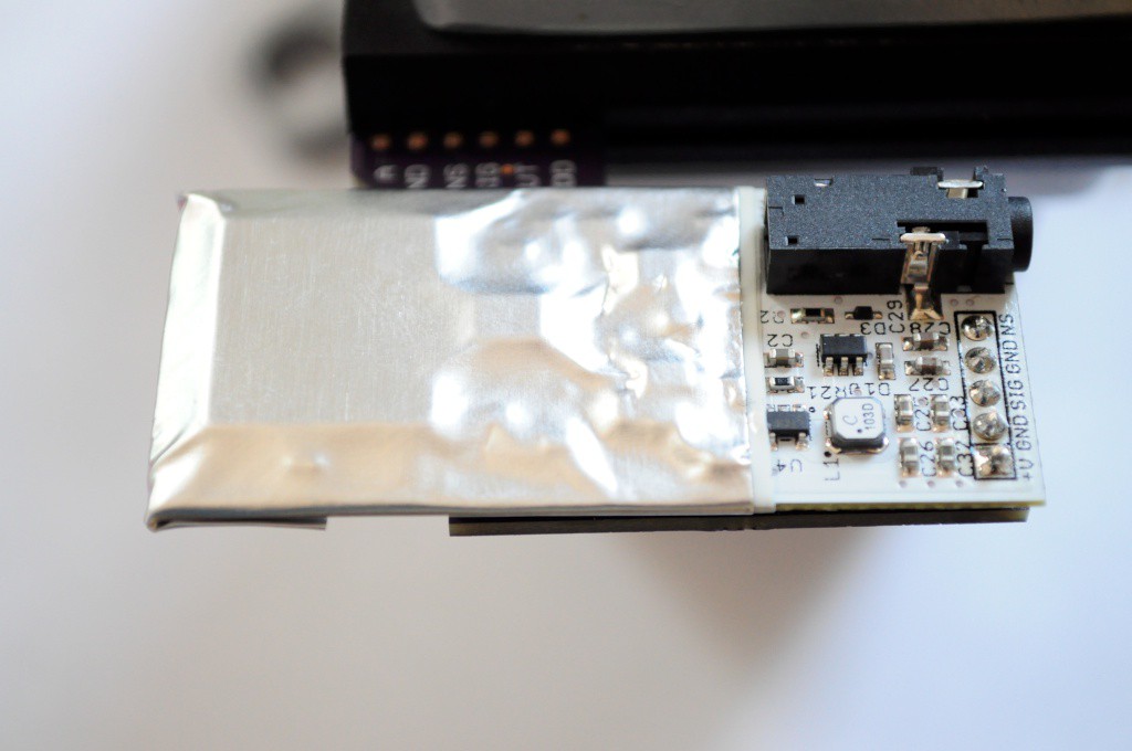
    The radiation backpack board allows the Radiation Watch Type 5 connector to the Arducorder Mini. This sensor board also contains an external comparator that allows the radiation sensor to be much more sensitive. You can experiment with different values for the calibration resistor, but a 2.7k 1% seems to have a good balance of signal-to-noise for me.

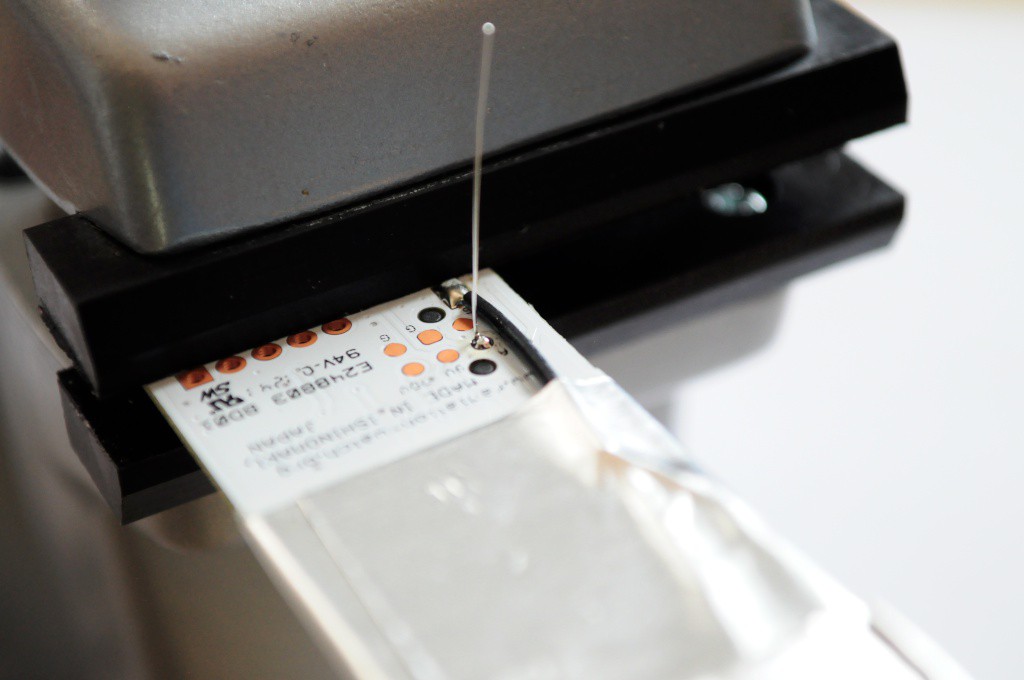
    In order to make the Type 5 extra sensitive, you will have to solder a piece of wire wrap to one of the test points. I recommend making a tiny loop at the end (with some tweezers), bending it 90 degrees, then hitting it with some solder paste. This connection has a very low voltage signal running through it, so be sure to do a good job soldering.

    The short piece of wire wrap solders to the backpack at TP1, which should be directly above the appropriate location on the Type 5.

    Congratulations! Feel free to connect this board up to an Arduino/Chipkit to test it out separately with the example firmware before continuing, if you'd like. The folks at Radiation Watch also have some Arduino-compatible Type 5 firmware that should work with this board (and takes the noise pin into account, if you're planning on vibrating the sensor).

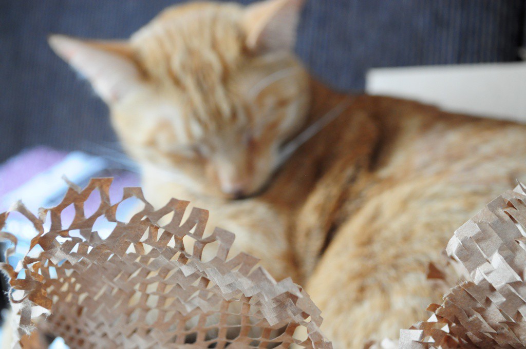
    Cat in Digikey box interlude

    Magnetometer/IMU Board

    This board includes an I2C address solder junction for the MPU9050. Ensure that it's shorted as above (otherwise it may conflict with the MPR121).

    Atmospheric Board

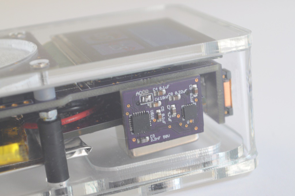
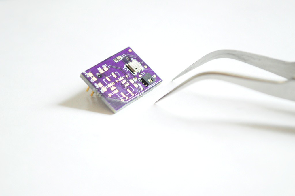
    This is the first revision of the Atmospheric board -- you'll want to put together the second revision, with the mosfets for the gas sensor.

    Lightning / UV board

    You'll need to use hot-air reflow or reflow the board twice to properly reflow the tiny microphone on the back.

    Capacitive Touch Sensor board

    The latest revision of this board moves all the components except for two pushbuttons to the bottom side of this board. The whole thing can be easily reflowed without issue. The two LEDs/resistors beside the button are "do not populate" -- they're included incase you want to have a fancy glowing OK button, but are untested.

  • 3
    Step 3

    http://www.tricorderproject.org/arducorder/chipkit-mplab-ide-0023-arducorder.ziphttp://www.tricorderproject.org/arducorder/chipkit-mplab-ide-0023-arducorder.zip

    Step 3: Constructing the Case

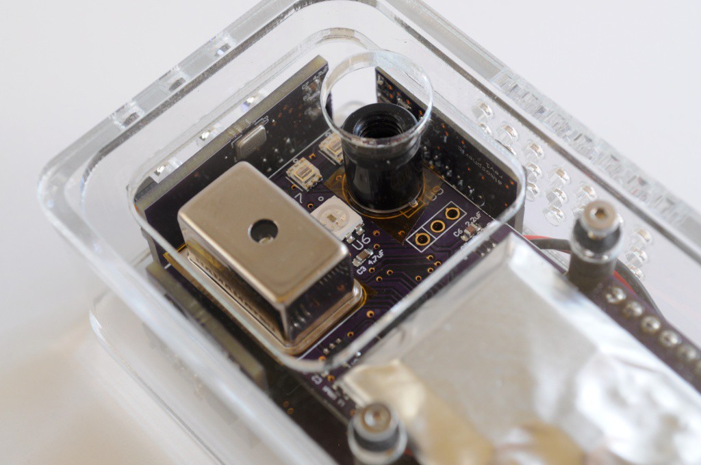
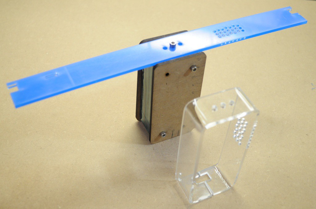
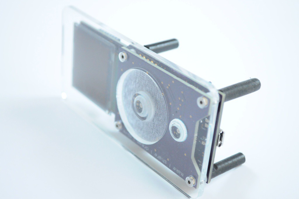
    This beautiful case is constructed from laser cut acrylic -- part of which is engraved to make the touch wheel, and buttons. The side is easily manufactured by bending a long strip of acrylic with a normal hot air rework station.

    Laser cut the acrylic

    The enclosure is constructed from 1/8 inch (~2.9mm nominal) acrylic. The pattern files can be found on the Github repository under "mechanical".

    While the back pieces are standard cutting and engraving, the side requires bending, and the top requires essentially using the laser cutter as a mill. The top process is as follows:

    • Cut the top plate outline and M2 holes
    • Cut an outline around the touch wheel
    • Manually remove the plastic shroud on the acrylic, so the next engraving step won't leave any of the protective cover in the touch wheel engraving area
    • Engrave the touch wheel (on the top of the acrylic) to ~2mm depth
    • Carefully flip the top plate in place, using the acrylic sheet that it was cut from as a placement jig
    • Engrave the bottom of the acrylic for the two button lips, and the buttons themselves -- these should also be engraved to ~2mm depth
    • Cut the buttons

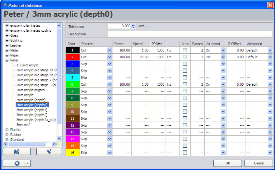
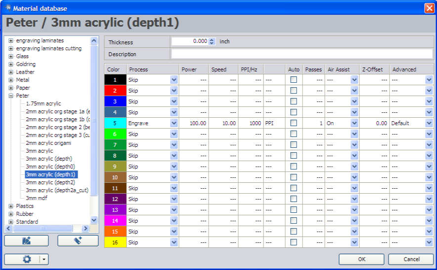
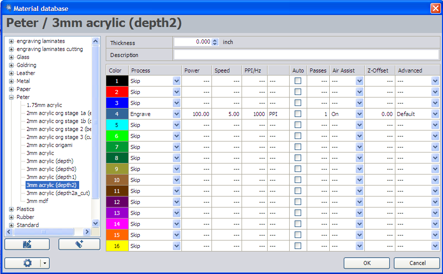
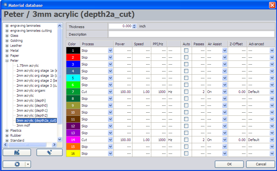
    You will need to experiment to find settings on your laser cutter that engrave to the required depth -- this will take a few minutes of experimenting. The settings that I use for our Trotec 60W cutter at Xerocraft are:

    Initial Cutting Step

    Touch Wheel Engraving

    Flip piece -- engrave buttons and button holes

    Final step -- cut buttons out

    Side Piece

    Cut out the bending jig out of 3mm MDF. There will be one extra middle piece that isn't required. The holes should snugly fit some number 6 screws, and hold the jig together. Don't forget to include a nut in the captive slot, so that you can securely hold the large side piece in place while you bend it.

    This step takes a bit of practice, so I recommend cutting out a view side pieces to practice on. Using your hot air rework station set to around 250C, heat the bends one at a time until they very slowly bend into beautiful curves. For the two long pieces, I attached a counter weight on either end for leverage (Just taping a small screwdriver to the ends). This helps gravity along a bit. Try not to force the pieces -- let gravity do the work, and it'll look better.

    It takes about 5 minutes per bend, or about 20 minutes total. If you have an actual acrylic oven meant for this, then you're job is a little easier -- although be careful not to bend the straight pieces, or it may end up looking more like a Picasso.

    Assemble

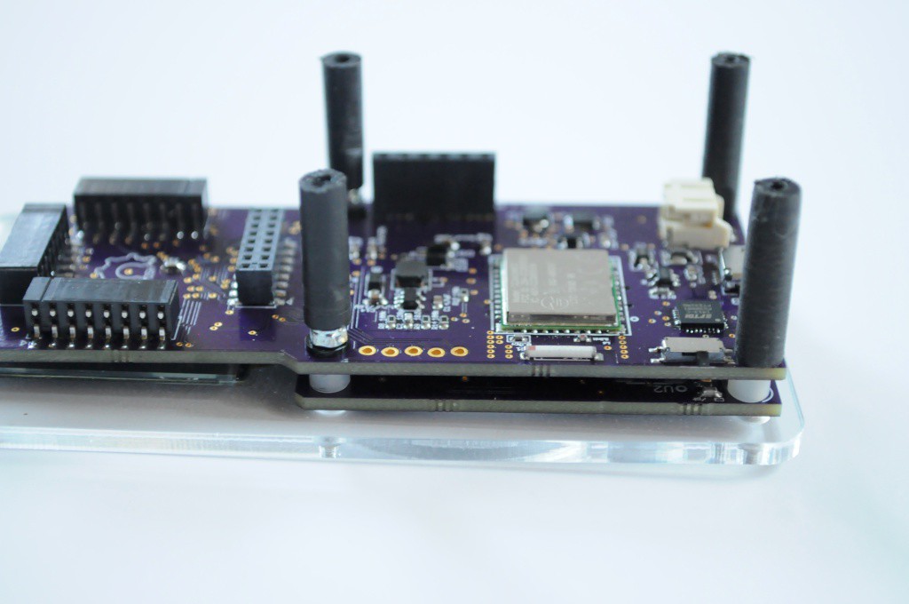
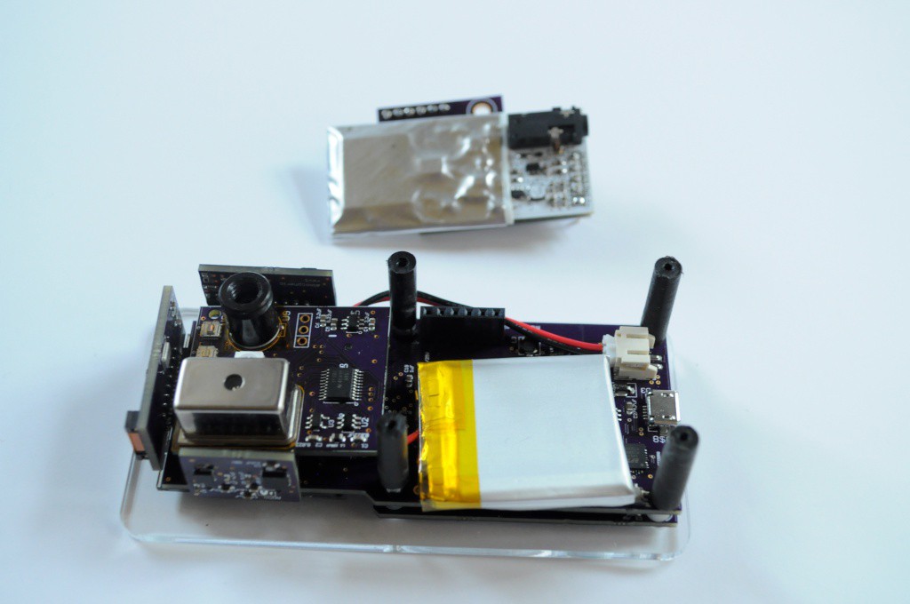
    Countersink the four holes on the top plate. Using four M2x16mm countersunk machine screws, bolt the capacitive touch wheel board to the motherboard. Place four 3mm high M2 spacers between the boards. The two middle bolts should have M2 nylon washers, and M2 locknuts.

    Attach four M2-tapped 5mm diameter delrin standoffs. You'll likely need to quickly machine these yourself, or purchase some nylon standoffs and tap them yourself. These act as the main fastener for the bottom two holes.

    Ensure these are snug, but not too snug. It's critical that the acrylic faceplace makes very good contact with the capacitive touch wheel for normal operation.

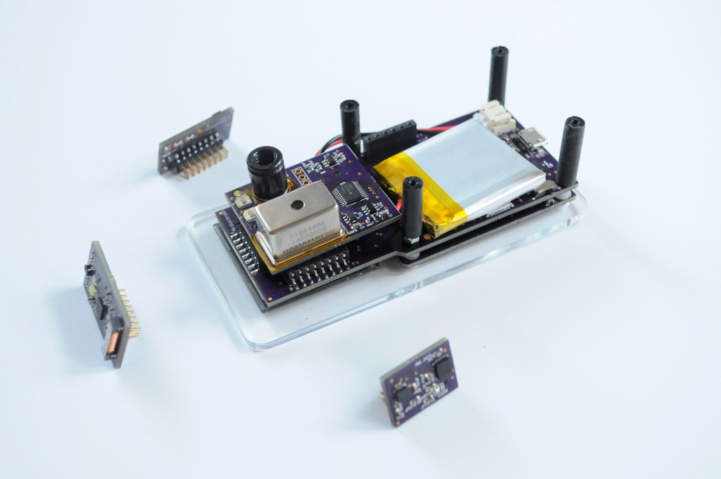
    Attach the battery, with the cable snaked over the top of the spectrometer board connector to take care of any slack. Attach the spectrometer board next, then the three side-mounted sensor boards.

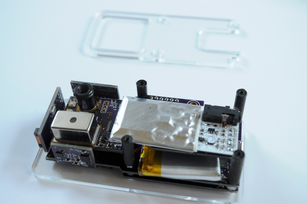
    Next up, attach the radiation sensor board. This should snugly fit between the standoffs, keeping everything in place.

    Next we'll attach the first bottom plate -- this one snugly fits onto the four 5mm standoffs, and provides a lip for the side piece to rest on.

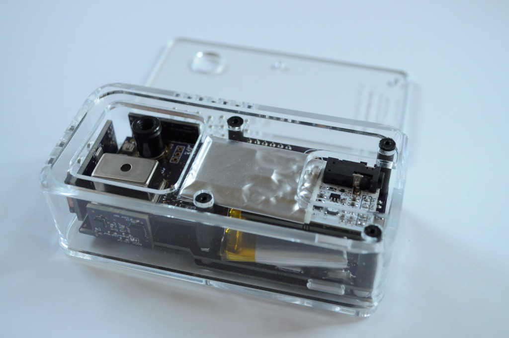
    Next we'll place the side piece on -- this should snugly fit around the top bottom plate

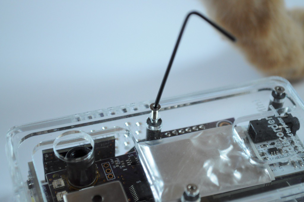
    Last, we'll install the bottom plate with the engraving. The four M2 holes here should also be countersunk. This acts as a retainer plate, very snugly keeping the sides together without any adhesive, so that you can take it apart to tinker without issue.

    Fasten with four M2x12mm countersunk machine screws.

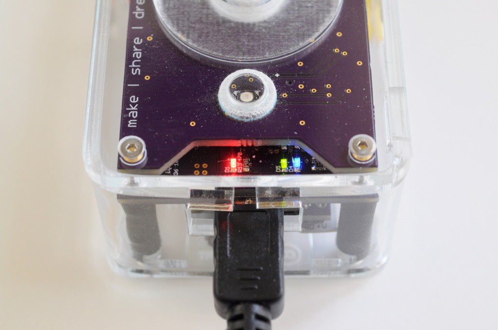
    Plug in the USB cable, and view the beautiful LEDs telling you how great a job you did. Red means the battery is charging, green and blue mean serial communication over USB for firmware programming. If you haven't already, download the Arducorder-modified ChipKit IDE, which updates some of the Arduino libraries towards 1.X compatibility. Grab the latest firmware from the Github Repository (currently test2k) and program the device. The firmware is very large, and will take a few minutes to upload and verify.

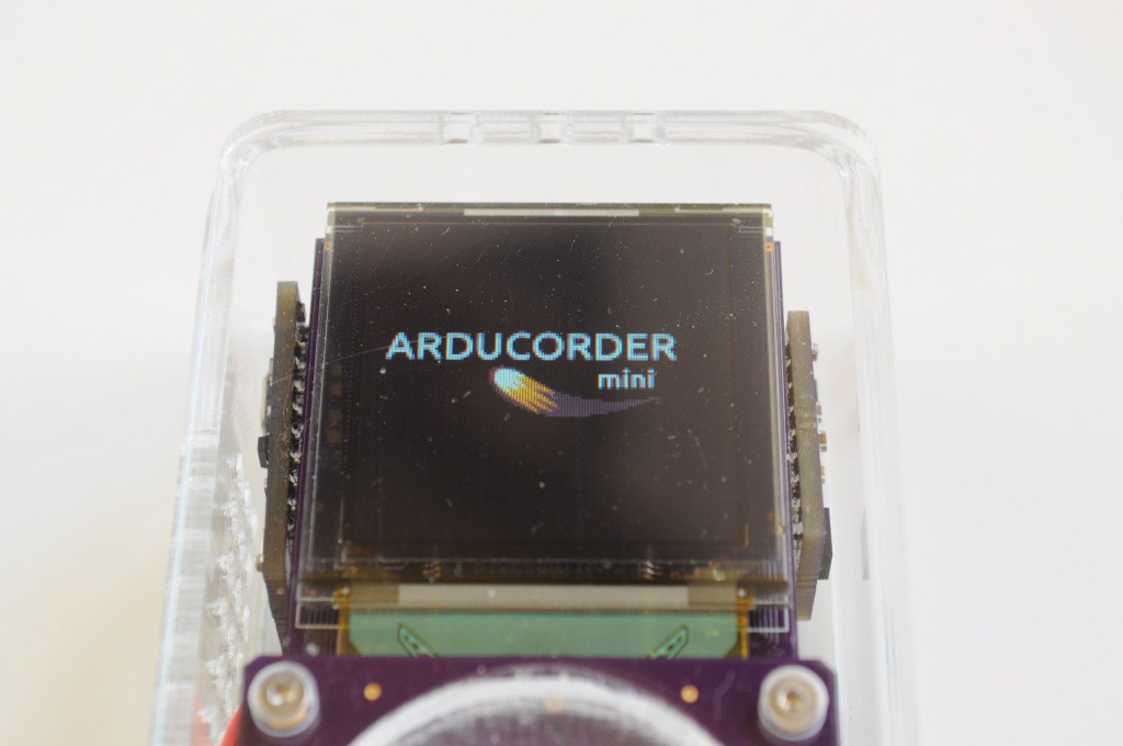
    The firmware will display this splash screen during boot up. It should be on the screen for a few seconds while all the sensors are initialized.

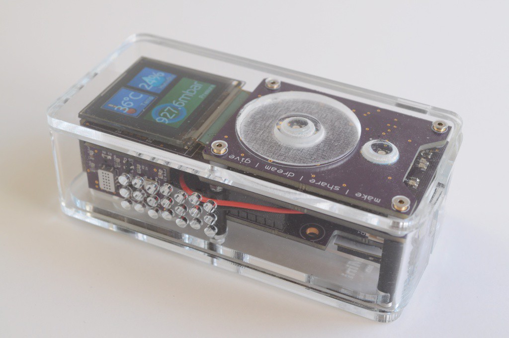
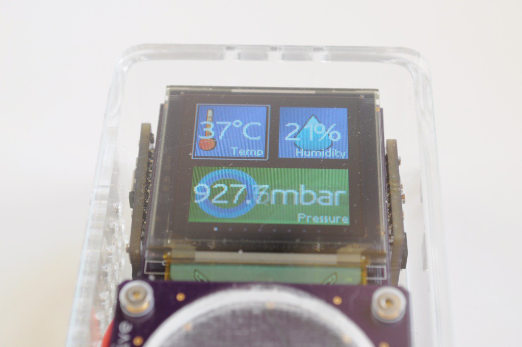
    After booting, your Arducorder Mini should begin to display the tile interface. Go explore the world, and share your discoveries with your friends!

View all 3 instructions

Enjoy this project?

Share

Discussions

Noman wrote 10/28/2014 at 10:15 point
Dear Dr. Jansen, please accept my heartiest congratulations. I am following the development since I first saw your blog entry (The Shape of Things to Come: the Mark 5 Arducorder) earlier this year and wished somehow I can buy or build this. Only I know how excited I am see this project come to reality and finally completed. Although competition is strong, I am sure you will have made your mark and will catch the first place easily. You know this little gadget will save me from buying half a dozen devices on my wishlist including Apollo Board (Approx $200), Type 4s Radiation Watch (Approx $100), Flir 1 ($350+shipping), Sensordrone ($200+sipping), A spectrometer (Min $500 plus), a weather-station with Lightening sensor ($150+) and an imu ($75+), so otherwise I have to spend $1575 plus shipping plus separate battery and charging solutions, extra weight, carry options and bulge in my pockets in addition to a fight with my life partner. The worth of this device is obvious and I would like to keep 3 accessory switchable boards along with as per my field requirement, including laser rangefinder (like lidar lite) , IR detector & communicator as well as a GPS (like navspark I already have). Please no sooner did you win the prize, tell me when you are going to launch and at what price or if I could buy the first prototype in this final video, really!

  Are you sure? yes | no

relias36 wrote 10/15/2014 at 17:29 point
Hello Peter, i just joined this site and found your project it looks very interesting. I'm a mechanical engineering student so i do not know much about making and designing computer hardware but I am still interested in trying to make one of these devices. Is there any way that i could use your board designs and have them built or could i possibly buy one from you?

  Are you sure? yes | no

Robert Hoffman wrote 10/14/2014 at 23:27 point
do you plan on trying to mass produce it?

  Are you sure? yes | no

David wrote 10/14/2014 at 10:03 point
Congrats on making the Top 5!

BTW, I'm really liking that Arduino-compatible Hamamatsu Spectrophotometer sensor. After the competition, if there any chance of seeing its code separated into a new Arduino Library?

  Are you sure? yes | no

peter jansen wrote 10/14/2014 at 17:03 point
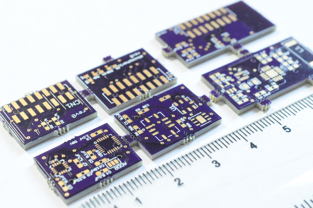
Thanks David! It really is a beautiful little instrument. The driver is already standalone ( https://github.com/tricorderproject/arducordermini/blob/master/firmware/test2k/SensorSpecHamamatsu.cpp / h), and includes some example code at the top, with the exception that one of the methods does resample and export the data into a SensorBuffer() (a circular buffer storage class used by the Arducorder mini for efficiently storing data and graphing it). You could include this too, or just comment out that method and access the data directly.

I have standalone test beds that I use to write and validate the drivers before incorporating them into the main Arducorder Mini firmware (it takes a few minutes to compile and upload, and so the testbeds get that down to ~10 seconds), and either just before or shortly after the competition I'll try to package these as separate Arduino Libaries!

  Are you sure? yes | no

peter jansen wrote 11/05/2014 at 00:27 point
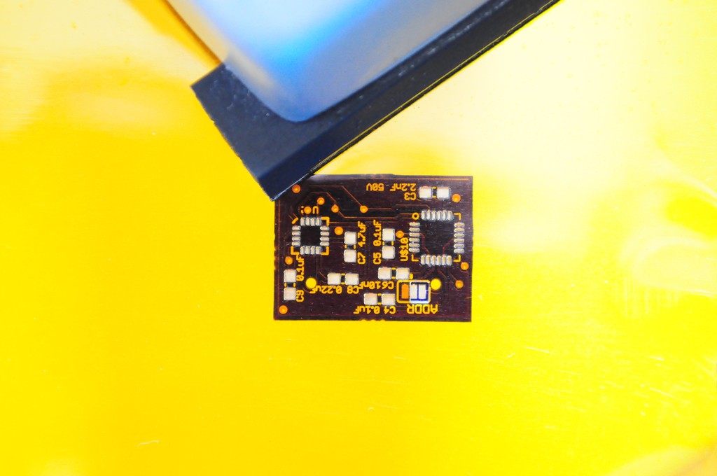
Update: these standalone examples are available here: https://github.com/tricorderproject/arducordermini/tree/master/firmware/examples

  Are you sure? yes | no

Ryan Shill wrote 10/14/2014 at 04:32 point
You should throw GPS on board for the Mark 6!

  Are you sure? yes | no

peter jansen wrote 10/14/2014 at 17:14 point
I've been thinking about this too. I removed it because it's large and everyone
carries around phones that are very good at map applications right now, but I
think it's important enough to warrant coming back. There isn't a lot of sensor
real estate left, but I have been thinking of replacing the microphone with the
Venus638, or even sneaking it on the back of the capacitive touch sensor board.
I designed something with the 638 in it last year, but I used a very small
antenna (and don't fully appreciate RF design, I work with much shorter
wavelengths), so maybe someone from the community with GPS experience can lend a
hand after things are less busy in a few weeks! The sensor boards are meant to
be part of an ecosystem that's easily modified or added to by the open source
community, with a minimum of effort. :)

  Are you sure? yes | no

vipersan wrote 10/15/2014 at 20:27 point
I think EVA-7M from u-blox is bit smaller, has higher sensitivity and consume less power.

  Are you sure? yes | no

peter jansen wrote 10/15/2014 at 23:35 point
Thanks! That looks like a wonderful chip -- 3.3V @ < 20ma draw while running, and only 7x7mm! Unfortunately it doesn't look like it's regular stock at any of the major distributors, and having to go through the manufacturer usually means a minimum order quantity and long lead times. I'm trying to keep it as easy for folks to source parts and build as I can -- hopefully a major distributor starts carrying these or a similar part!

  Are you sure? yes | no

Noman wrote 10/24/2014 at 21:20 point
Please also have a look at Venus868F. http://www.skytraq.com.tw/news/news2014Jul8.html it seems economical at $3 per module.

  Are you sure? yes | no

n49o7 wrote 10/13/2014 at 21:51 point
This is truly from the future.

  Are you sure? yes | no

peter jansen wrote 10/14/2014 at 17:18 point
One of the folks at Ars Technica once claimed in an article that I might be a time traveller from the future borrowing Berlinghoff Rasmussen's business model... I had no idea who it was, so we looked it up, and it made the lab mates and I laugh *so hard*. http://en.memory-alpha.org/wiki/Berlinghoff_Rasmussen

  Are you sure? yes | no

vipersan wrote 10/13/2014 at 21:45 point
Few suggestions:
- upgrade MLX90620 thermal camera to Flir Lepton,
- add 2-3 Mpix camera,
- HTU21D and BMP180 replace with BME280 (it's not yet in production, but maybe you can get engineering sample),
- add ALS (ambient light sensor) - IR / IR+visible sensor eg. MAX44009,
- add distance measurement feature.

  Are you sure? yes | no

peter jansen wrote 10/14/2014 at 17:30 point
Thanks. The challenge with most of these is a combination of size, cost, data, and tractability, and this is largely a device that's about balance. The standard configuration tries to strike a very good balance of sensor coverage with cost, while allowing folks who want extra functionality to design their own boards and modify the software very quickly. I would love to see someone design a small camera with a footprint on the order of 1-2cm sq with an integrated framebuffer that could be accessed over SPI. Similarly I'd love to see a small distance sensor with a good range, but right now many distance sensors have a large volume. Even the small maxbotics ultrasonic rangefinders would take up nearly the entire volume of the spectrometer/thermal camera board. That being said, it would take an hour of work to put together a sensor board that contained only the maxsonar, if one wasn't interested in the spectrometer/thermal camera. Eventually someone will make a very small distance sensor, and I would love to place it on the Arducorder Mini, or a future device.

  Are you sure? yes | no

Jordan D. Ulmer wrote 10/12/2014 at 20:36 point
Wow What An Awesome Open Source Instrumentation Project! Thank you for making this project so nicely documented! What type of design modifications and distribution costs would this project be looking at for a "3rd world" implementation?

  Are you sure? yes | no

reciprocum wrote 10/01/2014 at 14:09 point
This project is just perfect!
I wish all the hardware can be made available in a kit form as soon as possible.
Willing to support it right away if presented at kickstarter platform.

  Are you sure? yes | no

Marcus Vinter wrote 10/07/2014 at 11:38 point
I can't agree with you more.

  Are you sure? yes | no

Kojote wrote 10/08/2014 at 14:44 point
Jupp, same here

  Are you sure? yes | no

matt venn wrote 11/06/2014 at 22:12 point
+1 from me too

  Are you sure? yes | no

Ronny wrote 10/01/2014 at 10:54 point
Hey guys. What do you expect when the development process goes to rollout for public? I really would like to have that personally and in our store here in Switzerland.

  Are you sure? yes | no

peter jansen wrote 10/03/2014 at 21:28 point
Hopefully soon!

  Are you sure? yes | no

Andrej Mosat wrote 09/21/2014 at 18:22 point
Hi Peter, excellent project.
I was reading your questions on mini spectrometer page. One of them was: how to better connect the grating to the enclosure. I use double-sided automotive 3M foam tape, which just works. Maybe you already use the same system, but I could not find how you actually do it. You would also like to use 4mm optics, I might have some suggestions, but again, could not find exactly what the design requires, like the focal length. What is your workflow in programming / debugging / engineering the PIC32 ? It seems like Chipkit Max32 with the modified Arduino / PIC32 platform. Have you found a better diffraction grating? I have an answer to manufacturing of precise, cheap optical slits. What would be the quickest & plug-n-play way to obtain and test your mini spectrometer? Thank you!

  Are you sure? yes | no

peter jansen wrote 10/03/2014 at 21:17 point
Hi Andrej, the transmission for the open mini spectrometer is small enough that it just sits in place, and tends to stay (but you're absolutely right, in a real environment you'd want to use a dab of glue or something to keep it there). The open mini spectrometer is basically a pinhole camera, with the transmission grating at the end of a deep, wide slit, so there currently are no relay optics. This, of course, is non-ideal. If you'd like to experiment with making a better optical head, then the sources files are available at the link above -- I use oshpark for boards, and the parts are available at digikey. Unfortunately if you're not comfortable with soldering surface mount parts, there's currently nowhere that the boards are currently off-the-shelf. Maybe someone will post them on tindie!

  Are you sure? yes | no

Steve Pomeroy wrote 09/14/2014 at 04:17 point
Sweet project. Have you considered using a pre-made GUI/OS layer? You could build on top of things like Linux, QT, Android, etc. and save a ton of dev time.

I suspect one of the things that really make a project like this shine are the way the data are interpreted and visualized, which would be pretty hard to do with an entirely hand-rolled GUI layer. Cheers!

  Are you sure? yes | no

peter jansen wrote 09/16/2014 at 16:56 point
Thanks Steve. Microcontrollers are very different than desktops, and have much more modest computational resources, so they're not usually able to run OS's, and the few that they can run are a little complicated to code for. The PIC32MX I'm using has the most RAM of almost any commodity microcontroller (128k), which is barely enough for a display backbuffer and some rolling buffers for the sensor data. :)

Developing an attractive and intuitive GUI from nothing but a pointer to video memory is a bit of work, but it's also a lot of fun, and very rewarding. Architecting it well in this case also means that folks will be able to customize it with very little background knowledge, and (more generally) that Arduino/ChipKit folks will have a lightweight GUI library that they can use for completely different projects.

Over the past few weeks I've been browsing through a lot of design concepts for ideas, and designed something like a Live Tile interface that's controlled through the scroll wheel. It's very intuitive, and looks beautiful, and feels very good on the actual device. There's still a bit of work to do (and the deadline is coming up), but I'll post pictures shortly! Stay tuned!

  Are you sure? yes | no

justin.m.riddle wrote 08/23/2014 at 01:48 point
This looks freaking incredible. When the first round is ready for purchase I'll be first in line. My dad is a superintendent of a golf course, and could use something like this to detect soil and water chemistry, weather conditions, and we could even build a sensor that interfaces with his irrigation system. So many possibilities! Good work, I'm very impressed. I'm guessing this is going to get you to space.

  Are you sure? yes | no

peter jansen wrote 09/02/2014 at 01:48 point
Thanks for your kind note. I hope you and your dad will get to have all sorts of fun with one, I'd love to see how it works out for that environmental monitoring task!

  Are you sure? yes | no

Jasmine Brackett wrote 08/15/2014 at 19:16 point
Hello Peter,

there are a few small things you can do to your documentation give your project the best chance of going through to the next round of The Hackaday Prize.

By August 20th you must have the following:
- A video less than 2 minutes long describing your project. I see you have a couple of videos. Put a link to the one you want our judges to watch most in the external links section.
- At least 4 Project Logs. You have this covered.
- A system design document. Is it this image https://static.hackaday.io/images/5974661405800489211.jpg?
- Links to code repositories, and remember to mention any licenses or permissions needed for your project. For example, if you are using software libraries you need to document that information. You can highlight these in the project details or external links section.

Thanks for entering. Good luck.
Jasmine

  Are you sure? yes | no

peter jansen wrote 08/17/2014 at 04:36 point
Thanks Jasmine, I think I've put everything up today, including the updated video, the system design diagram, and uploaded the current source snapshotto the GitHub repository!

  Are you sure? yes | no

James wrote 08/14/2014 at 00:30 point
maybe in a future version you could add a full-color lcd, and an infrared camera for monitoring heat, and plant chlorophyl levels.

  Are you sure? yes | no

peter jansen wrote 08/14/2014 at 01:03 point
Hi James, the OLED is a beautiful full 16-bit colour (the graphical user interface is just unfinished), there will be a low-resolution thermal camera, and the spectrometer may be able to monitor chlorophyl levels. :)
  Are you sure? yes | no

[deleted]

[this comment has been deleted]

peter jansen wrote 08/07/2014 at 01:33 point
I mean, you're not wrong -- if you don't value science based on observation and measurement, science education, or being generally interested in learning more about the world around you, then yes, this device will be of little use to you.

If you've taken high school chemistry or physics, you should know about measurement error, and that every measurement from every device has some accuracy and repeatability associated with it -- for example, 25C +/- 0.1C. This is a fundamental property of all sensors (electrical engineering), or the nature of measurement (physics), and is true of a one dollar sensor or a million-dollar instrument. That being said, nearly all of the sensors have been chosen to be particularly accurate, especially for their price point. I think there was an example floating around where the atmospheric pressure sensors are so accurate that, under ideal conditions, you could nearly measure someones height just by measuring the atmospheric pressure at their feet and head, and subtracting the two altitudes you infer from those pressures.

As to why I might be a trustworthy source on sensing and science education, Yes -- I do have a PhD, and have spent the last decade choosing to do academic research (for much less than one makes in industry), teaching, and donating my evenings to projects that help make it easier for folks to learn science -- because I love it, and think it does a world of good. But, as always, you should critically evaluate any source (including me) before you trust what they say.

All that being said, if (after taking time to sleep on it), you still don't understand why folks might find this project exciting, that's okay too. But now that you've (repeatedly) voiced your very strong opinion, I think there are lots of more productive things we can all do with our time.
Best wishes.

  Are you sure? yes | no

[deleted]

[this comment has been deleted]

peter jansen wrote 08/06/2014 at 16:45 point
I'm not sure what you mean -- the open source science tricorders I've been building for 7 years are clearly very real devices. In the case of this one, the Arducorder Mini, when complete it will have about a dozen different sensing modalities. It's basically a multitool for science, like a swiss army knife. So maybe your question becomes, where would you use a thermal camera? Where would you want to detect radiation? Where would you want to characterize the atmospheric conditions of an environment, or sense potentially harmful gasses? Where would you want to take the spectra of an object? And so on...

  Are you sure? yes | no

Piotr S wrote 07/30/2014 at 08:21 point
I fully support your Project.
Few things from my Point of View:
The Case Design should be more Handheld like an Remote
And when it comes to remotes. What about an IR Transmitter/Receiver Package?

  Are you sure? yes | no

peter jansen wrote 08/01/2014 at 05:00 point
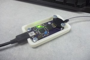
Hi Piotr, the industrial design shows that the Arducorder Mini is handheld, like a phone or MP3 player?
Could you make a scientific use case for an IR transmitter/receiver? And what wavelength?

  Are you sure? yes | no

Piotr S wrote 08/01/2014 at 08:53 point
I was considering that IR waves are everywhere.
And you could use it to read signals from Remotes and other IR driven Devices.
With the Transmitter you could even copy those Signals.
Greetings and thanks for the Questions :)

  Are you sure? yes | no

Fredwordsplat wrote 07/29/2014 at 17:20 point
I Recommend A Voltage Detector With a Detachable Housing and Wireless InfraRed Communications. Like Doctor Bashir uses to Scan Humanoid lifeforms For Injurys.
Image of Scanner :


http://2.bp.blogspot.com/-NP06Lgv6zyA/UFAflMA_WhI/AAAAAAAADBk/LMVzn_71k3c/s1600/Improved+Star+Trek+Medical+Tricorder+Papercraft.jpg

  Are you sure? yes | no

Similar Projects

Does this project spark your interest?

Become a member to follow this project and never miss any updates