 Curt White
-
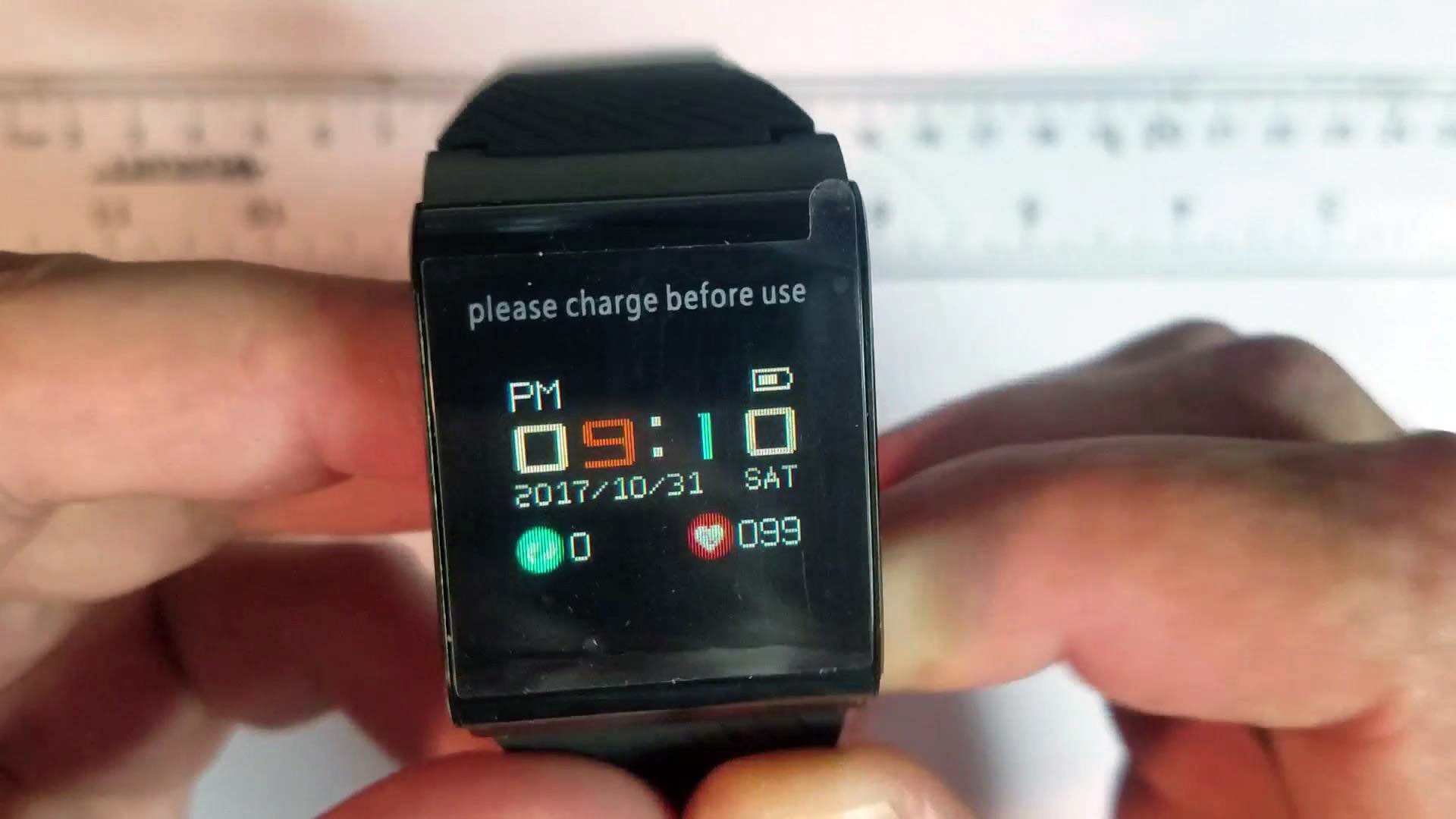
1Get a X9 Pro Activity Tracker
![]()
Aliexpress, Banggood, and Ebay are your best bet. Pricing will vary widely so it pays to look around.
LINK1 LINK2 LINK3 LINK4 LINK5 LINK6
NOTE: I have purchased many X9 Pro activity trackers. Some of them have a green PCB and some have a blue one. It doesn't make a difference for the purposes of this tutorial. The traces on the PCB are arranged a little differently but all the components are the same.
-
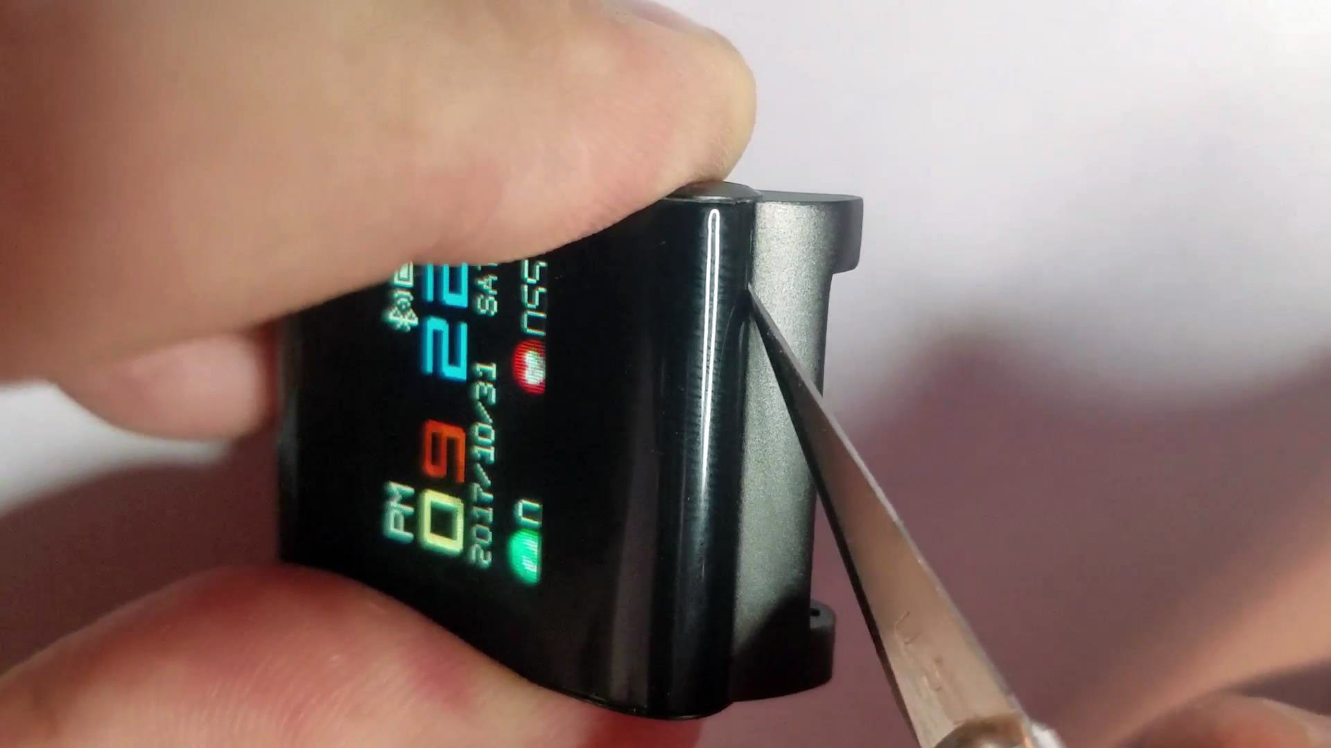
2Cut Glue Between Translucent Plastic Cap and Metal Enclosure Body
![]()
Use a hobby knife ("X-Acto" knife) to cut as much of the glue bonding the plastic cap to the metal body as possible. Getting a thin blade between the plastic and metal will gradually wedge the two apart. Take your time (I would budget at least 5 minutes) and work your knife all the way around the cap.
-
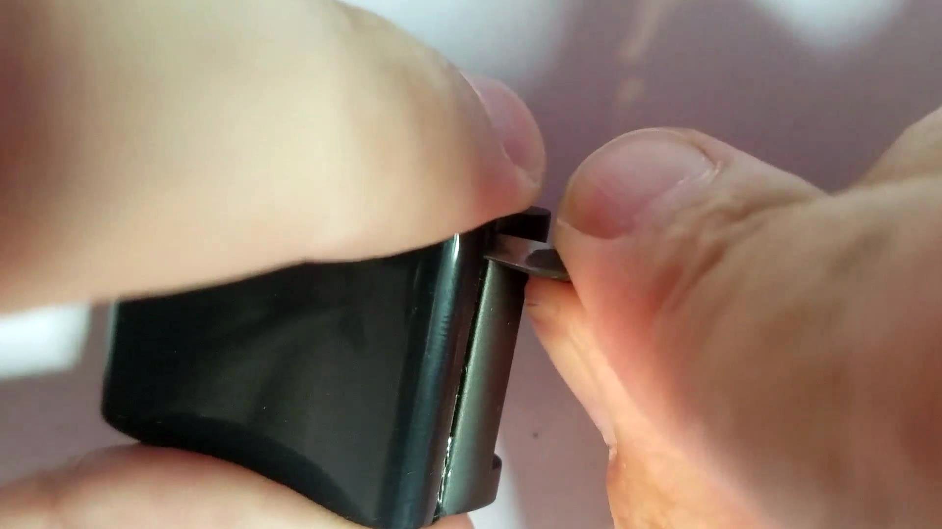
3Lift Plastic Cap Off the Metal Enclosure
![]()
Use a small screw driver or prying tool to carefully lift the plastic cap off the metal enclosure body. Take your time and work thy prying tool around the cap.
Separate the cap and put it aside for now.
-
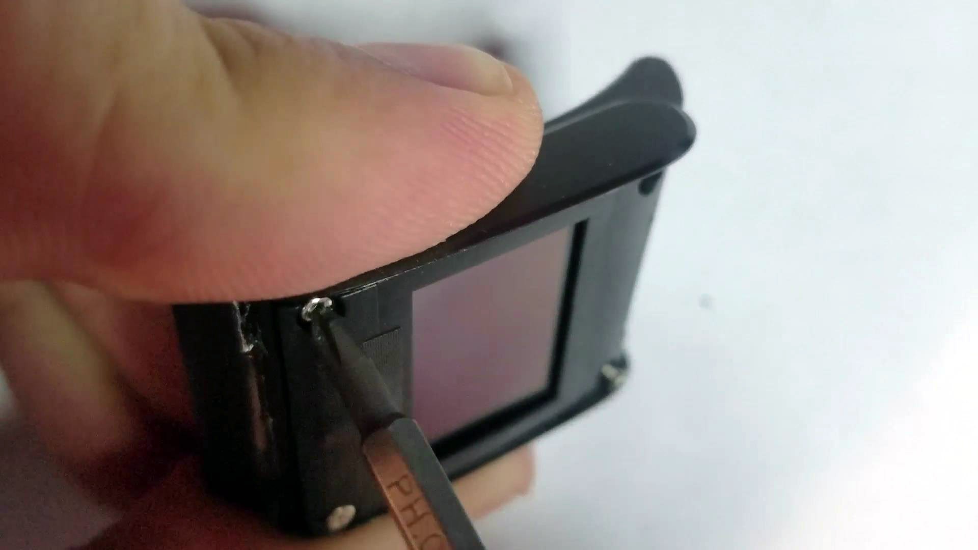
4Unscrew Plastic Retainer
![]()
![]()
Unscrew the plastic retainer and put the screws somewhere you won't lose them.
-
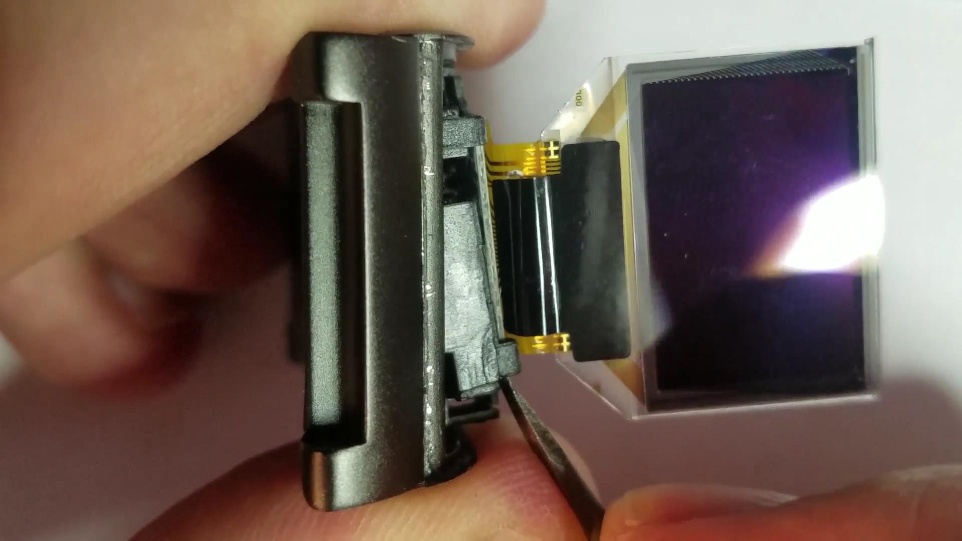
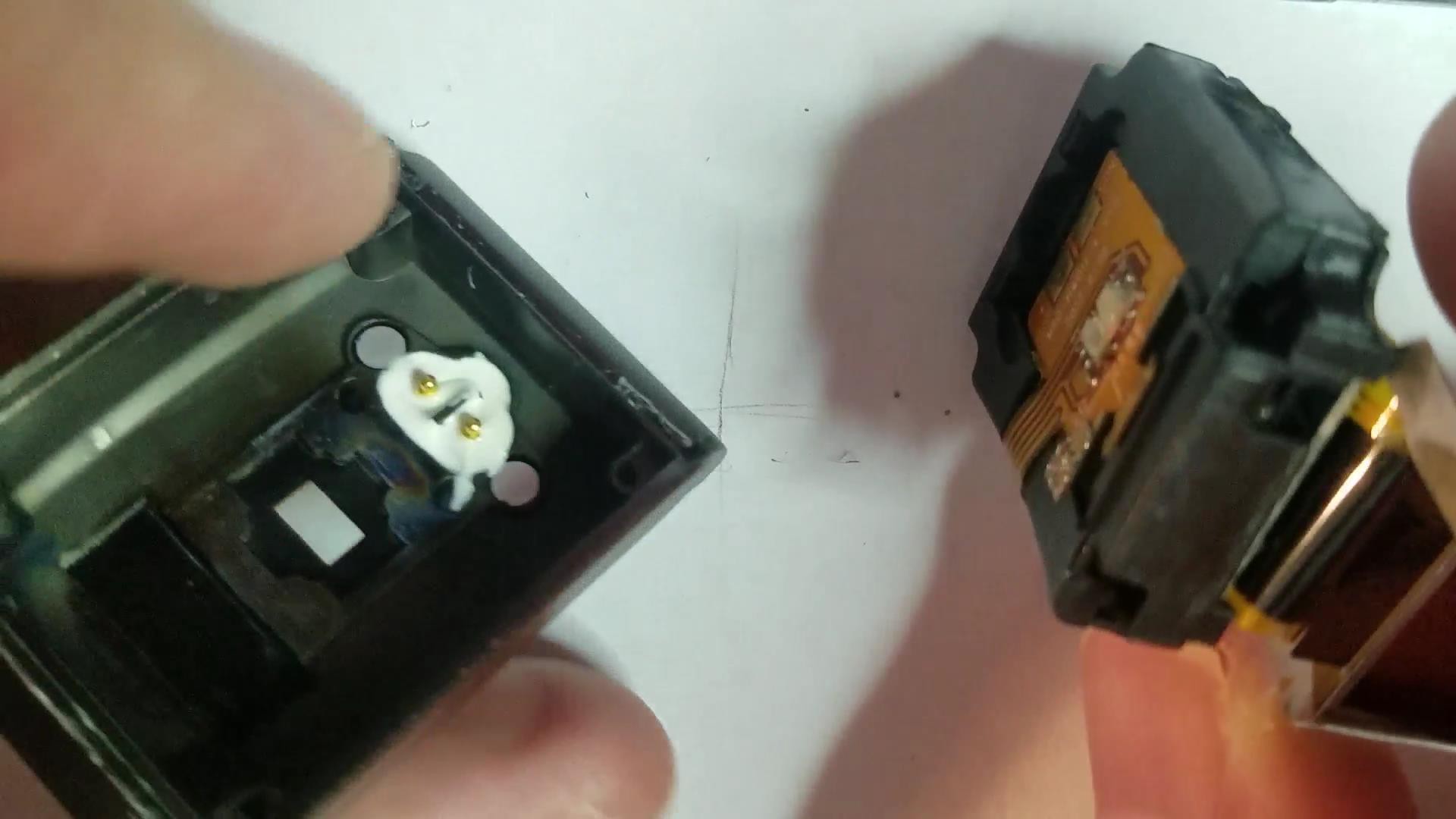
5Remove Inner Plastic Electronics Enclosure
![]()
![]()
![]()
Carefully pry out the internal plastic enclosure.
-
6OPTIONAL Remove the Main PCB From the Internal Enclosure
The PCB test pads that you need to solder are on the exposed side the the PCB, but all those cool chips are on the hidden reverse side. If you are like me you will definitely want to take a look. Carefully push back the plastic teeth retaining the PCB. You will see all the ICs in their glory and also the LiPo battery. Once you are done taking a peak put the main PCB back in the plastic internal enclosure.
-
7Coat the Exposed SWD Programming Connecting PCB Pads With Flux
I always use flux. Flux dissolves accumulated oxidized metal from the top of the pads, making solder bonds easier and stronger.
-
8Solder Wires to the 4 SWD Connection PCB Pads
You may want to dab some glue on the solder point to reinforce it but that is strictly optional.
-
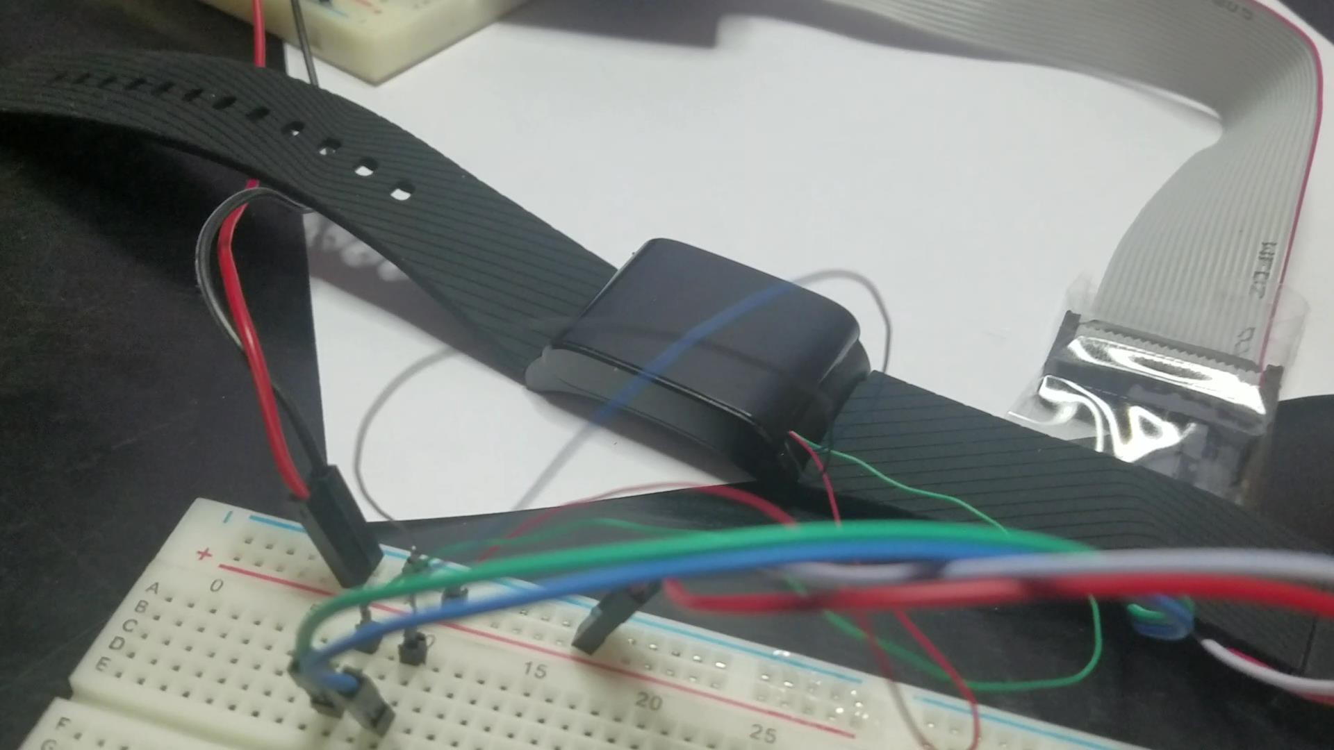
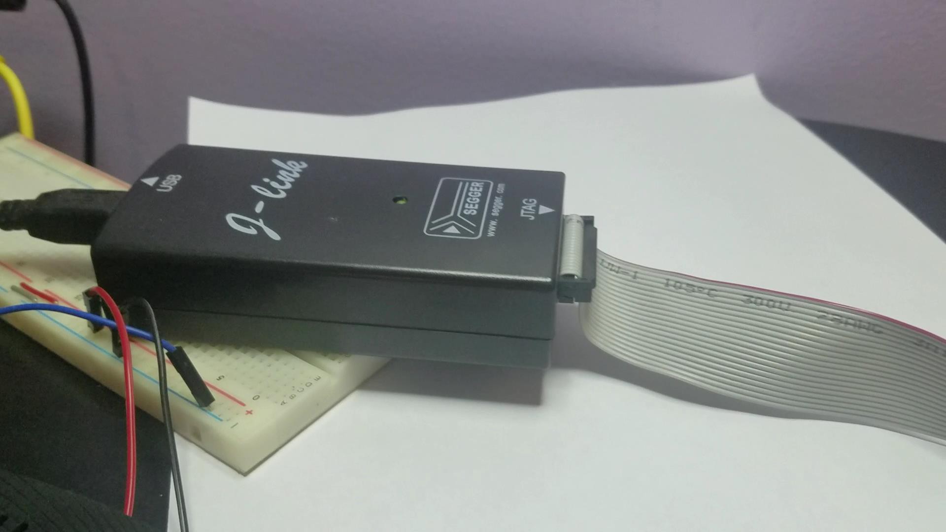
9Reassemble Device and Connect the X9 Activity Tracker Wires to an SWD Programmer
![]()
![]()
Cut a groove in the plastic cap for the wires to fit through and reassemble the device just like you took it apart. Connect the wires to a bread board. Connect the Ground and Voltage Supply wires to a 3.3v bench power supply, as well as the ground and reference voltage connections from your SWD programmer.
-
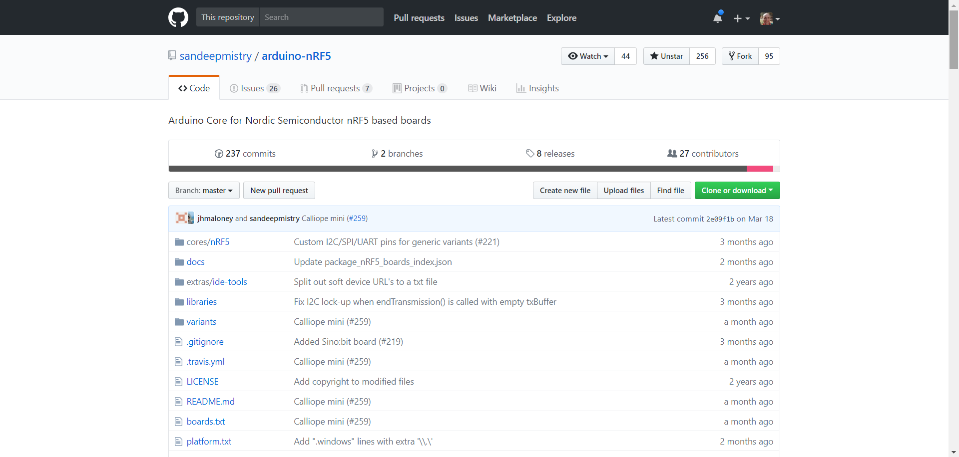
10Install Sandeep Mistry ArduinoCore Arduino IDE Package and Add X9 Variant From Project GitHub Repository
If you have not already installed the Arduino IDE, go ahead and do it. Then go to Sandeep Mistry's Nordic ArduinoCore GitHub repository (Arduino wrapper for the Nordic nRF5x SDK), download the ArduinoCore package and install on the Arduino IDE. There are excellent instructions in the GitHub repository README. Use the variant file for the X9 activity tracker found in the GitHub repository for this project.
![]()
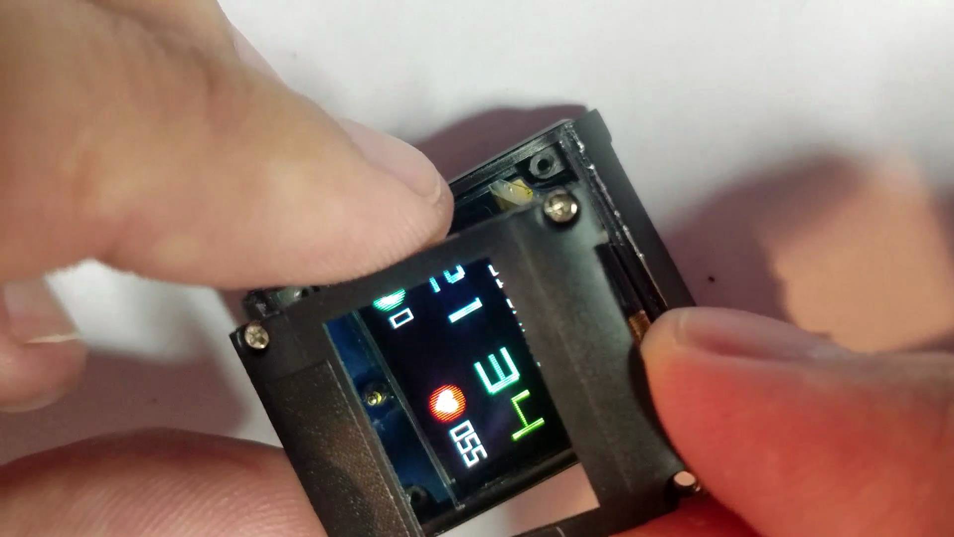
Load the nrf52_X9Project_OLED sketch (attached to this project as a file) into the Arduino IDE. Make sure board is set to "Wearable nrf52 X9" (will show up once you add my X9 variant), and that the SoftDevice (this option will show up after installing Nordic ArduinoCore) to "S132". These settings can be found under the Arduino IDE "Tools" tab. Under the Arduino IDE "Sketch" tab press "Export Compiled Binary". This will create a raw compiled version of your application/sketch in the file folder for the nrf52_X9Project_OLED sketch.
Hacking Wearables for Mental Health and More
Presenting the "Tingle" wearable for compulsive behaviors and a hacked fitness tracker wearable device prototyping platform.

Discussions
Become a Hackaday.io Member
Create an account to leave a comment. Already have an account? Log In.
Thanks for the wealth of useful information, these devices are amazing. Do you know how to build a package that can be flashed via OTA DFU rather than USB / J-Link ?
Are you sure? yes | no
I'm trying to develop a 24/7 hearth rate tracker for my grandmom (data sent automatically to raspberry server via bluetooh for historical data, and if some condition is meet, sent a alert via telegram). I have a nodemcu with ino file working sending data to google sheets and telegram conection, but I have just read your hack and this wearable is just wat I'm looking for. My questions are: do you have a picture how the j-link jumpers are connected? how bluetooth is linked to a device? HR sensors seems to be 4 and 29, and battery 28. I only want to show batery level and conection status, so
Are you sure? yes | no
cheers
Are you sure? yes | no
Yeah, there are two steps. You need the X9 variant file directory + contents (in the repo) into the nRF5x Arduino Core variant directory and you need to add and entry to the boards.txt file in the nRF5x Arduino Core install directory (in AppData). Instructions for the boards.txt entry can be found in a comment in the variant.h file inside the variant file directory (inside "Wearable-nRF52-X9" folder in the repo). Before you do any of this its a good idea to get the generic nRF52 variant working so you know everything is installed correctly and functional. nRF5x Arduino Core comes with a bunch of baked in variants including a "Generic nRF52" and "Nordic Semiconductor nRF52 DK" both of which should allow you to at least go through the process of programming the X9 - even though the firmware won't work unless you are using the X9 variant. In depth instructions can be found on the nRF5x Arduino Core GitHub repo README: https://github.com/sandeepmistry/arduino-nRF5 .
Are you sure? yes | no
how do you add the x9 variant? Does it need to be registered somehow?
Are you sure? yes | no