 Lahorde
-
1Step 1
Project has been done in Amiqual4Home Equipex Creativity Lab - https://amiqual4home.inria.fr/
Description
Power your robot, chair, couch, with an overboard! Gives anything two wheels drive!
Hoverboard are chinese low cost products. Hacking it can give a meaningful platform to give a two wheels drive platform to anything
Prerequisities### hardware
- [Two hoverboard motors] (http://gyro-service.com/moteur/19-moteur.html)
- [Hoverboard mother board] (http://gyro-service.com/cirquit-carte-mere-smart-self-balancing-wheel/17-carte-mere.html)
- [36V battery] (http://gyro-service.com/batteries-samsung-smart-balance-wheel-gyropode/18-battterie-22p-samsumg-ou-de-qualite-equivalente.html)
- optionally [daughterboard] (http://gyro-service.com/accueil/23-plaquette-contacteur-semelle.html) to understand motherboard / daughterboard communication
- Arduino Teensy 3.1/3.2
Setup
### Components Analysis
Refer ifixit for a detailed analysis of hoverboard.
Interesting parts are :- how do these components interact?
- is it possible to control hoverboard externally?
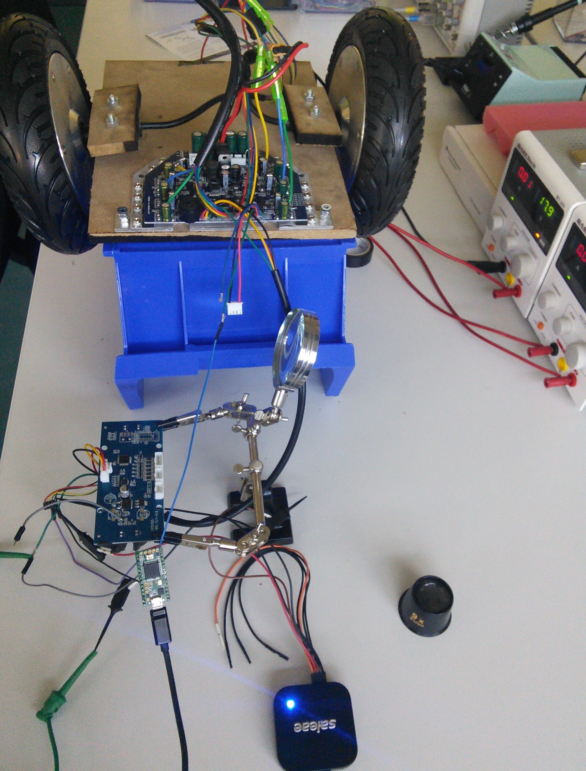
### Daughterboard / motherboard communicationDaughterboard can be used either on right/left. So we only bought 1 daughterboard to decode Daughterboard / motherboard exchanged data.
We connected a single daughterboard to left and left motherboard/daughterboard connectors.
In this case when rotating daughterboard, wheels are rotating in two different directions.![]()
#### Protocol
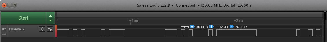
Probing a logic analyser on daughterboard 4 wire connectors gives some interesting info :- logic level = 3.3V
- bit duration ~ 38.10µs => baud rate ~ 26300kbps
![]()
- there is no clock provided on given lines => Async protocol
Is it a standard protocol?- may be UART? Some clues can help... Green and yellow lines of daughterboard are connected to [STM32F103](http://www.st.com/content/ccc/resource/technical/document/reference_manual/59/b9/ba/7f/11/af/43/d5/CD00171190.pdf/files/CD00171190.pdf/jcr:content/translations/en.CD00171190.pdf) PA2 - UART2 TX and PA3 - UART3 RX
In order to get UART parameters :
- get maximum frame length taking for example a frame of 0 or a frame of 0/1/0/ and so on... After that you will conclude (helped with Salae logic ananlysers):
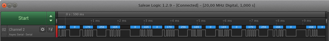
Daughterboard send data to motherboard using 3.3V UART @26300bps - 1 stop bit - no parity bit.
#### Exchanged dataHere are decoded data with UART analyzer in Salae Logic software :
![]()
Do not move daughterboard, power motherboard and read decoded data. We can see :- redondant 256 integer : it is frame start => frame size = 6 9bits integers
Now let's play with photodiode used in daughterboard contacts :- if we hide at least one of it last frame integer = 85
- otherwise last frame integer = 170
If 170 value is sent to motherboard : motors won't be driven (it means user to not have its feet on hoverboard)
4 remaining bytes must be decoded : two of these bytes repeats.
Rotating daughterboard gives indication :- little move only modify a frame integer => this integer must be low significant 9bit
- more rotation modifies other integer => rotation seems to be encoded on 2 9 bit integers.
Rotating around 0 helps us :
Angular value is coded in 2x9bits signed integer value (2's complement)
We can check it is only an angular value applying linear acceleration to daughterboard. In this case angular value do not change.
## hardware
In order to control hoverboard we need an external MCU to :- send left and right foot angular position => we need two UART Tx lines supporting 9bits UART @ 26300bps
- optionally read daughterboard current postion (for tests) => we need 1 UART Rx line supporting 9bits UART @ 26300bps
Different MCU can be used, we could use UART bitbanging libraries... But a nice solution is to use teensy 3.1/3.2 :- it runs @3.3V
- [9 bit uart supported on Arduino Core] (https://www.pjrc.com/teensy/td_uart.html)
- 3 avaialble hardware UARTs!
### software
As we saw in our first tests, when same daughterboard is connected to two motherboards/daughterboard connectors :- wheels rotating direction is different. Hoverboard is rotating
In this case same angular value on left foot and right foot is sent to motherboard.
In order to have hoverboard moving forward / backward we must apply for example :- a positive angular value on right foot daughterboard Uart
- negative angular value on left foot daughterboard Uart
From that simple code is provided here :
[Refer code](https://github.com/OpHaCo/hoverbot/blob/master/hoverbot_embedded_software/teensy_hoverboard/teensy_hoverboard.ino)
InechoGoForward()function : it reads current angular value from daughterboard to control hoverboard in forward direction.
After testing we can easily :- control speed of both wheels when it is rotating in different direction (under load or not)
But we cannot :- control speed of both wheels when it is rotating is same directions (not under load). **In this case, motors reach needed value but quickly speed up until max speed**
We can suppose, closed loop algorithm on motherboard does not support forward / backward mooving when it is not under load.
## Commands
TODO
### Control commands
TODO
## Events
TODO
## References
* http://www.electronicspoint.com/threads/reverse-engineering-a-hoverboard-with-wheels-accelerometer.279098/
* http://drewspewsmuse.blogspot.fr/2016/06/how-i-hacked-self-balancing-scooter.html
## TODO
Low cost two wheels drive - hoverboard hack
Power your robot, chair, couch, with an overboard! Gives anything two wheels drive!
Discussions
Become a Hackaday.io Member
Create an account to leave a comment. Already have an account? Log In.
Did you gave supply for the red and black wire in the daughter board?
Are you sure? yes | no