Yann Guidon / YGDES
-
Dual-voltage power supply
11/19/2016 at 21:15 • 0 commentsThe system is getting a bit more complex... but bear with me ;-)
A previous log, Fanout and multi-rails power supply, came to the conclusion that 2 voltages were needed to kep the liaison capacitors from being polarised in reverse.
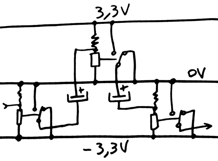
What came to my mind is this:
![]()
The logic output of one relay goest to a relay in the opposite rail. This way, the capacitors are always correctly biased. Alternating power rails is a method used in the first ECL circuits...
But this creates more new problems, that I will spare you (and leave as an exercise to the reader if you are versed in the art). Drawing the above circuit, it appeared that I was blindly repeating what I already knew, yet forgetting that the new and different context has more flexibility.
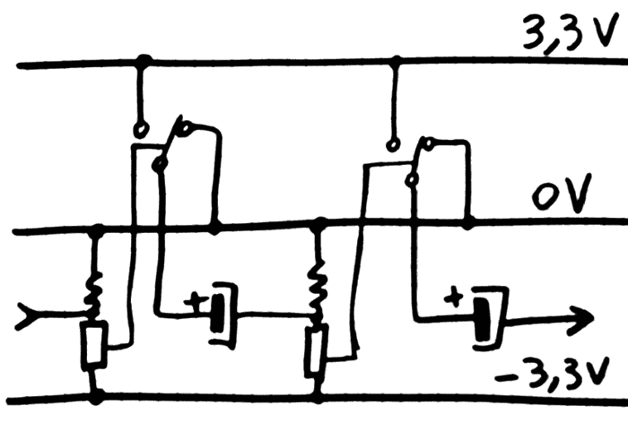
Unlike transistors with only 3 pins, the relay has 5 and it's possible to "shift" the voltage of the switch :-)
![]()
Then, the system is greatly simplified, there is no question about controling relays on both rails at the same time with a unique signal.
The main rail (0/-3.3V, but it could be reversed) can sustain most of the load (a constant 40mA/relay), while the positive side (0/+3.3V) must only sustain spikes (the average current is lower but it requires more decoupling).
Is is already known that the "latch" coils require a separate 3.3V power supply to isolate them from the spikes of other activities. Long coil strings also require another PSU at about 20V. So it's not really an inconvenience to have 4 instead of 3 PSU...
But wait!
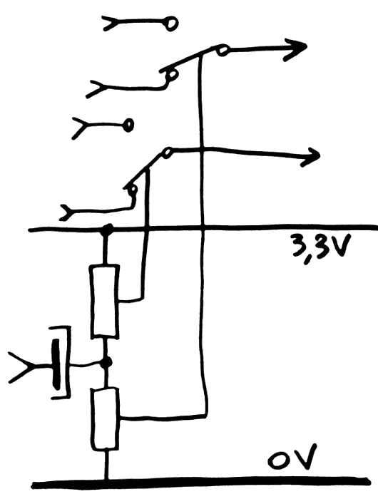
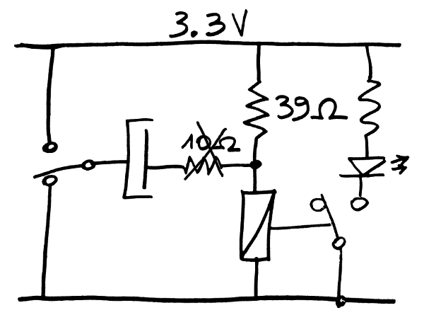
Since the bias resistor has the same value as the coil, what keeps us from replacing it with another coil ?
![]()
Yes, we get a DPDT with no increase in power consumption. Just make sure that there is no path that allows short circuits because the relays don't switch exactly at the same time.
This is particularly interesting for the carry logic, which is still being studied...
But this is not the end yet !
I mentioned that there is a need for a 20V PSU, to power the long strings of 8 relays with high fanout. The calculation is simple : 8 relays require 2V each to turn on, that's 16V, plus a suitable resistor to tune the string to at least 60mA. 18V won't do and I have some 20V PSU around.
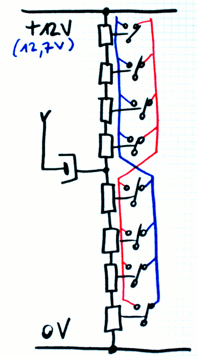
But the above DPDT circuit can be easily extended into a 8-pole pseudo-relay with prebias, using a bit more than 12V ! The bias voltage is approx 1.58V, or 12.64V for 8 relays. The working point can be adjusted on classic open-frame blocks.
The drawback is the higher quiescent current, but it will remain pretty stable during operation, preventing load-dependent fluctuations and heating.
Another auxiliary 12V PSU is required to polarise the liaison capacitor.
But the same 12/13V that powers the long strings can be used directly by the DC/DC to generate 3.3V, saving some complexity as well.
![]()
(note: the liaison capacitor should probably be increased from 100µF to 470µF because there are more coils to drive, but the increase of voltage might compensate as well. Anyway, more capacitance can increase the working voltage margin, when using relays with mixed characteristics)
Do you see the crossing in the middle ?
When there is a low-going pulse, the bottom relays get de-energised while the top relays "stick". And vice-versa. If all the data must be coherent, then the polarity must be exchanged somewhere.
The good news : it can simplify the wiring and control of the register set MUX8s.
The bad news : the power consumption just increased. Though probably not by much since some relays would draw >60mA anyway. But at least the heating is totally balanced and not load-dependent, which adds a bit of reliability.
Another bad news is that I must check ALL the relays for Von/Voff before wiring, which makes the #ReTest-RPi project more important.
You know what would be even better ? That the new circuit gets actually tested on the bench, because I've had enough bad surprises already :-D
-
Instruction ROM
11/16/2016 at 02:15 • 6 commentsI have studied the data RAM ( Read/Write circuit) but the instruction memory is not designed yet.
Actually I have not designed an instruction set or format so the following discussion will remain very prospective.
Magnetic memory wouldn't work with relay logic levels. The RAM needs to be refreshed too often. So far the only method that makes sense is an array of switches and diodes.
Ted inspired me to design a modular system with boards that can be swapped in/out for convenient programming and reuse of common code routines, so at least 4 boards are required in a bus. I suppose each board could contain about 32 instructions...
With this modular approach I can implement the program memory boards with various methods :
- DIP switches for easy development (but they are not cheap)
- 0.1" male headers with jumpers for more stable code (a bit cheaper but don't lose the jumpers)
- soldered diodes on a higher density matrix for stable libraries (math routines ?)
To ease development, a companion board should be created to provide a visual aid for assembly and disassembly. This is the same idea as the #Discrete YASEP's "hardware assembler" but with relays ;-) Now, maybe the "hardware assembler" should be simply integrated in the actual instruction decoder, to save on hardware and keep up with any ISA changes. A switch will simply determine if the current instruction comes from a front panel (easy for single stepping) or one of the boards... The front panel will provide a first practical interface to develop and debug the execution unit while the actual program counter and instruction memory are being developed.
So basicly, we have an electrical interface : X instruction bits and a strobe...
20161117
TODO : when a code routine is done, hardwire it with RED LED. More voltage drop but OMG it will look so amazing !
20161121
The LED will not sustain enough current to switch the coils (60mA)
Since there will be several program boards of different types, let's ponder what the first ROM will do : initialise all the CCPBRL states to a known value and contain the routine that refreshes the DRAM.
The refresh routine might work as an interrupt and needs to save a few registers before doing its job so a few (2? 4?) scratch registers are needed. How to implement them is a new question to answer...
-
Fanout and multi-rails power supply
11/14/2016 at 03:12 • 0 commentsIn the log Capacitively Coupled Pre-Biased Relay Logic, I have explained the discovery that capacitive coupling with 100µF can effectively replace the 22 Ohms liaison resistor. The working voltage range is increased. This also reduces the power draw because a current path is removed, the average required power is lower.
Why do I bring thing again ?
Well, I tried to drive several coils from one relay. With resistive coupling, things didn't work well.
The 22 Ohms resistor is great for driving one relay.
For two relays, the current paths become more complex but it still works somehow. With 3 coils loads, things are not good. Some relays barely switch. This is because the voltage swing is not symmetrical anymore, as seen on the 'scope.
The CCPBRL can solve this. But this creates a new type of problems...
My test circuit worked but it is considered as a "fluke" because electrolytic capacitors don't like being backwards-biased.
Electrolytic capacitors are chosen for their cost and capacitance density. Non-polarised capacitors are larger or too expensive. So there is a need to bias it properly.
The "solution" is to use more than one supply voltage rail. For example, +3.3V and -3.3V.
For a single output, this works as expected : the signal drives the slave coil(s) through a capacitor that is connected to the opposite rail.
For 3 coils, there is a new possibility : tie the 3 coils in series and use the higher voltage (between -3.3V and +3.3V).
It's pretty easy but the power supply becomes a different story.
The funny part is that I encountered this situation while trying to create additional voltages (-3V and +6V) using a charge pump. The thing more or less works but is not worth continuing.
Higher voltages are required at least for the RAM system. A higher charge should provide a stronger "kick"...
Trying to "stay true" to antique design methods and using technology that my grandfather has used, the natural approach is to use a dual-windings transformer (torus if possible) followed by a couple of diode bridges and a crazy amount of capacitance (I'm covered on that part).
I'm not covered on the transformer part though. Most voltages I find are at least 9V but I need 2×3V.
At 3.3V working voltage, add the diode bridge drop : 4.7V. Then the transformer output should be around 4.7/1.4=3.35Vac. The lowest secondary I can find is +6V/-6V. Maybe I'll need an autotransformer in front (a Europe-USA converter, 240-120V), but I'll loose efficiency and room...
So for now I'll simply use a couple of cheap switching PSU.
-
Read/Write circuit
11/12/2016 at 04:34 • 9 commentsI don't know why the TIM-8 uses diodes.
I have redesigned the RAM array without them and it is much simpler now:
![]()
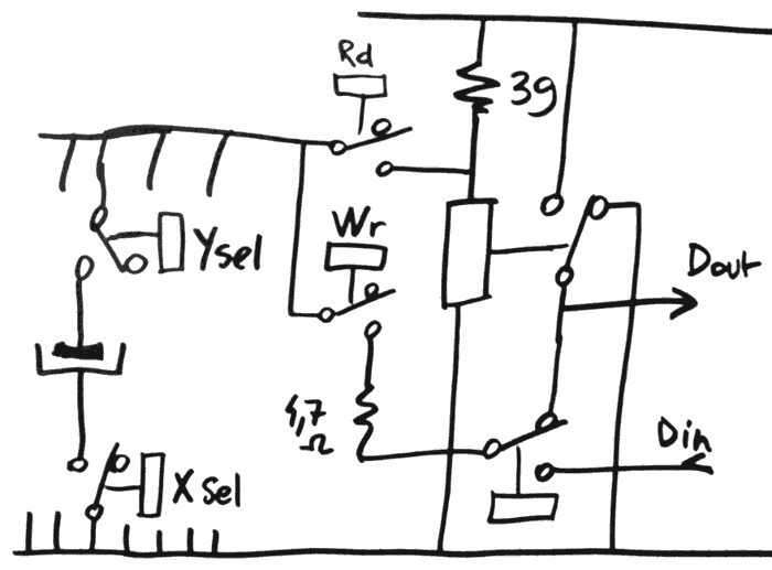
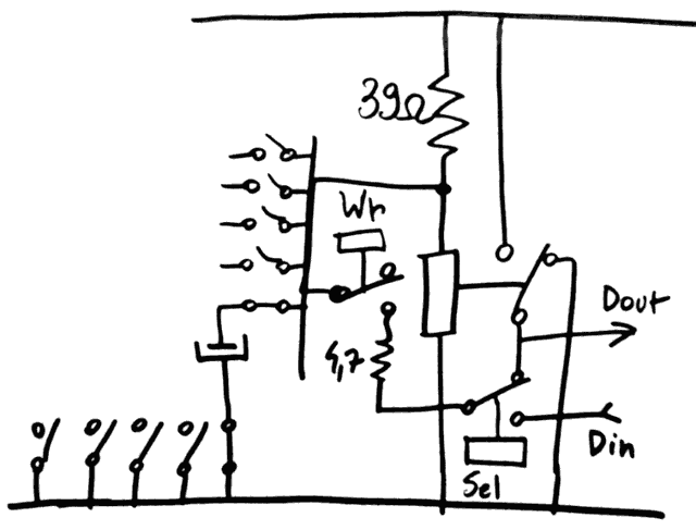
It can get even simpler as it appears that the Rd switch is not really necessary. 3 relays per bit, nice.
![]()
Only 3 relays, now, but let's not forget the steering relays that move data around the globule.
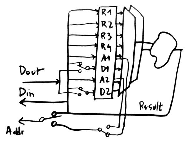
![]()
Yes I should use "Dread" and "Dwrite" instead of Din and Dout. But you get the idea. That's 7 relays per slice, which can be added to the globule boards.
I implemted and tested the circuit at the top.
It doesn't work.
I'm overlooking something but what ?
-
Diodes.
11/12/2016 at 01:58 • 2 commentsIn the previous log Capacitively Coupled Pre-Biased Relay Logic I have characterized a new twist on the prebiased relay circuit. But the RAM cell contains more than a capacitor, there is a couple of diodes. It was time to verify their influence on the circuit.
![]()
The bad news : the working voltage range has shrunk to only 3.35-3.75V, giving an ideal voltage of 3.55V. That's a very narrow tolerance (+/-5%) and kills my hopes of using a dumb unregulated tranformer, as any ripple will be an outright parasite. The range also varies with the frequency of the signal, as the capacitor is charging through the 39 Ohms of the coil and the resistor. This explains why the working range is pretty symmetric this time.
For this circuit, I'm using the eternally famous 1N4148. You can get them in bulk quantities for "dust" price, only resistors can be cheaper... The drop voltage is around 0.7V, less at small currents, but in this case it only deals with spikes. The instant drop might rise to 1V or more, with no limiting resistor.
How can the range be extended again, providing more ripple noise immunity ?
- First idea is to use Germanium diodes. I love this idea because it "feels true" to the spirit of the retrocomputing. The drop voltage is halved and that gives about 0.7V of additional range back. However sourcing 1000s of them will be much less cost-effective than the 1N4148 (whose prices can go lower than 0.005USD/pc) and they are rated for a lower current (usually 20mA for point-contact Ge diodes such as 1N60). I don't want to push this limit.
- Then the logical contender is to use Schottky diodes. Cheaper, bulk modern stocks, available in all sorts of ratings. I have a reel or two waiting to be used but it's too modern and does not have the "dirt cheap" appeal of the 1N4148 in axial packaging. I'd like to keep through-hole parts for easier manual soldering, SMD is great but not in all the cases.
- Figure out a charge pump trick to over-charge the cap ?
Wait. In the above circuit, the cap is only charged mid-way (Vcc/2) through the resistors, and a write circuit must reinject a full-swing voltage, not Vcc/2.
Approach 3. now makes sense because it's not only "dirt cheap" (the 1N4148 are not a major expense in the project) but also faster. The cap is charging through resistors and the 100µF takes a while to reach a voltage that allows the next cycle to trigger correctly. I have tested the thing manually at a few Hz but I'll need a faster (50Hz ?) system !
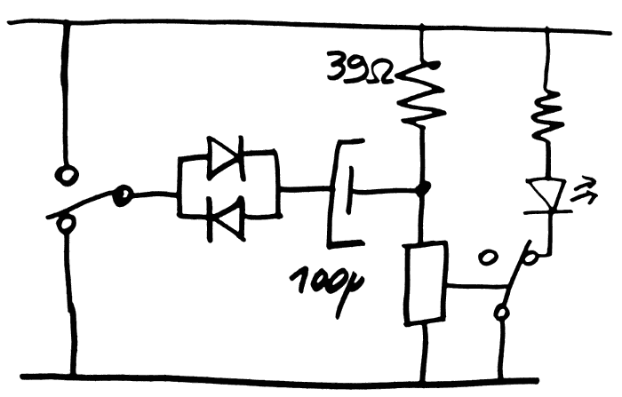
Yes, now it becomes obvious that the cap is charging in average to Vcc/2=1.6V, after it has delivered its "kick". There is the need to recharge it, if the bit was found to be "1". To write a "0", just inhibit the rewrite, or do like the below circuit (to be tested). The "cost" is "only" a second relay per bit of datapath. There were 16 relays, now 32, that's one box of RES15 :-D
![]()
To increase efficiency, I've imagined a diode which prevents the cap's current from flowing back to the supply rails. The diode adds some drop, which is compensated by the adjustable resistor in parallel with the main bias resistor. This could allow fine-tuning of the sensitivity.
I'm getting nervous about the sequencing of the control pulses of the RAM now...
There is the W/R pulse to generate at the proper time. I hope that this version works well because other versions need the sense relay to be "cleared" before "read", which adds more relays (to de-energize the sense coil) and more sequencing to do.
Oh and I forgot a critical aspect : how do I write data ? That's one more MUX/relay...
Furthermore, if 100µF is not a concern, the whole word will use 16 bits. Writing a word means charging 1600µF, more than the typical 470µF decoupling capacitors. A small series resistor is required on the write line...
And now here comes the actual trick question!
Why does this RAM array even uses diodes at all ?
Using relays, it's possible to connect both electrodes of the capacitor to form a 2D, and even 3D assembly. The more I look at it, the more I fail to understand what the diodes bring. It may have been useful for TIM-8 but here ?
....
Gone are the diodes.
-
Capacitively Coupled Pre-Biased Relay Logic
11/11/2016 at 07:04 • 6 commentsOh my, another acronym... CCPBRL doesn't particularly roll on your tongue :-D
The preliminary design of the RAM made me wonder about the values and characteristics of the parts: the storage cap, the sense relay, etc.
So I experimented and the result is pretty awesome.
![]()
Against my initial intuition, this system works well.
First, as a purely logic system, the capacitive coupling actually reduces the average operating current. It also helps to extend the operating voltage range a bit. The series resistor might be useful, but not necessary. This new system swapped a passive part for another, which enhances the circuit ! I'll have to see if this also increases the speed.
I'm working with 100µF but it is functional with 22µF & 10 Ohms. The lower limit might be around 10µF but I couldn't find one in my parts bin... 6µF is not enough though.
As a RAM storage component, the retension/refresh period could be in the minutes range. The series resistor would be removed. Oh and it works with a single voltage, no need of complex diodes or higher voltages ! However, the 1N4148 silicon diodes drops 0.7V, I have to check if this still works...
Now it's funny how, by looking at the RAM part, I discover how to enhance this already simple and efficient circuit !
Time to find the cheapest capacitor bulk suppliers...
-
Memory arrays for relay toy^Wcomputer
11/11/2016 at 00:13 • 2 commentsThe computing unit is fine but I have not even covered the memory aspects.
I'll leave the instruction memory for later, since I'll need quite a bit of it. I'm focusing on Data RAM (less memory needed), and there are 2 memory ports.
I decided to use a unified adress spaces because this saves relays. At first I didn't want to deal with multiplexing, but the amount of relays needed to decode addresses is significant... I will use 16-bits words and see how to make a scalable system, where I can add more bits without changing the whole thing. Hopefully I could reach a few Kbits (one or two hundred words).
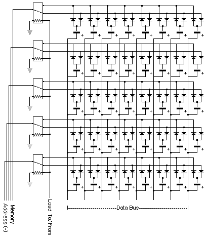
Let's have a look at the capacitor-diodes array (as already developped for the TIM-8 computer). From the website:
![]()
Using one relay per bit would be incredibly noisy, power-consuming, expensive and large... OTOH I have to plan for an idle loop that will read (and refresh) each word.
1N4148s cost almost nothing and I can find rather cheap capacitors. On top of that, since I have characterised the relays, I know the triggering parameters and the required current to flip a state under a pre-bias condition.
The TIM page does not tell the capacitance of the array, but I suppose it's somewhere around 100µF. The capacitor must supply enough charge to flip the sense relay and it's about 3.3V and 25mA or something (for how long ?). I am thinking of a way to increase the "kick" by using higher voltages, so I'm looking at 25V capacitors, which is fine is I use 20V for the high fanout control signals. 16V caps are cheaper though...
Of course, all of these suppositions must be tested/verified and TIM's sense and refresh circuits are not explained so I'll have to figure them out.Update: yeah, it was good to test the sensor circuit. No need of 25V capacitors, 3.3V works nicely.
Oh and I probably should think about adding parity protection to the RAM.
Update : this is more complex than that...
The diodes have been removed (this also saves a layer of relays), the type of capacitor is being refined... See the following logs.
-
Bitslice architecture update
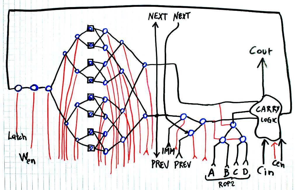
11/09/2016 at 01:36 • 4 commentsThe latest diagram of a bitslice is shown here:
![]()
Blue circles are SPDT relays, red lines are control, black is data.
There are some notable tweaks since the original design :https://hackaday.io/project/14628/gallery#1974aa13d487c3bb02791679e8e65966
For example, no memory input anymore, since it's directly connected to the registers. Logic operations are now using the ROP2 system and the shift is performed before the bit operation (interesting shift & compute combinations could emerge).
The carry logic is still not defined but there is a lot of inspiration to draw from Dieter Müller. Funny how I somehow reinvented his findings before I even read his work.
Overall, the majority of the design is composed of MUX. MUX8, MUX4 and some more in the adder logic. That's important because the PBRL cells are seldom used, maybe at the ROP2 level. The rest is a lot of control signals that drive the relays with more swing and less power.
Update: I forgot to include the "zero" flag "open collector" output... A huge wired-or is essential for the control circuits!
Here's an updated version:
![]()
-
A more reliable PBRL parameter
11/08/2016 at 21:25 • 19 commentsAfter the ring oscillator has run for almost 2 days, I have seen that the operating parameters had shifted a lot.
I reduced the liaison resistor: from 39 ohms down to 22 and now the working range is approx. from 3 to 4V.
![]()
I've left it run under 3.3V and despite the higher control current, the average current is still 200mA for 4 relay (50mA/relay) and because voltage is lower, the power is lower too !
After 1h, the range has drifted to 2.75..3.80V but not shrunk. So far, 3.3V seems to be a good voltage.
Back to 3...4V... It's no relays, it's yo-yo's !
2.90V...4V : the range seems stable now.
About 3 million cycles later... Still ringing.
3 days, now, and it's still stable.
The working range hasn't changed much.
I think I proved my point :-) -
Relay endurance, speed and reliability
11/07/2016 at 01:07 • 7 commentsThe question of the relay quality has resurfaced and I want to characterize my stock.
What is their endurance ? The only way to try is to make them work, fast and hard, and see how long they last. The best circuit for this is a ring oscillator.
I have had bad experiences already (see the #SPDT16: 16-bits arithmetic unit with relays logs) but this time I know these relays better and I shouldn't make some blunders. In particular, the PBRL reduces wear on the contacts so a string of relays will do a good delay line.
Another interesting side is that the relays' speed can be measured, simply by the ferquency of a ring, depending on the number of relays.
The ring did not work as easily as expected, I had tried one or two relays in series but not 4 or 5.
Something I learned : decoupling is even more critical ! 470µF for 4 relays seems to work... Otherwise, I start to increase the PSU's voltage. With enough capacity, the voltage doesn't need to increase. They don't tell you that in the books !!!
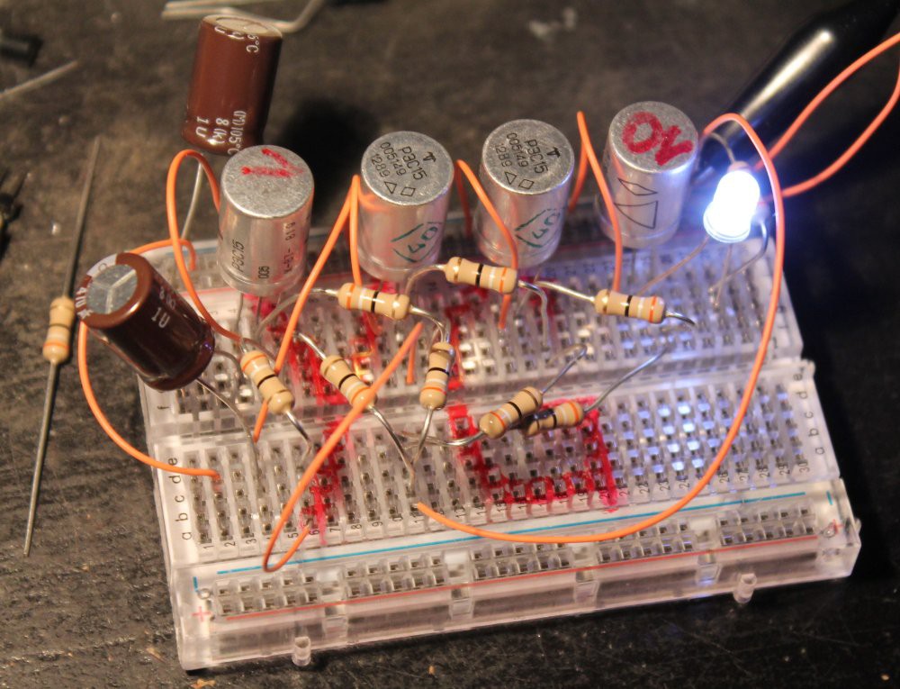
OK, with the decoupling solved, the voltage becomes important. It drifts in a few minutes, and this can actually be seen on the 'scope, as the duty cycle is affected. The sweet spot seems to be around 3.8V..4V but it might change. It's important to find a voltage that works in cold and warm conditions.
![]()
Because of the crazy quantity of bouncing, it's hard to measure a precise frequency. But I estimated the following:
- 2 relays: Tcycle=15..17ms
- 3 relays: Tcycle=23ms
- 4 relays: Tcycle=30ms
It seems that each relay adds about 7ms to the cycle time, which includes the high and low states. A relay seems to increase the chain's delay by 7/2=3.5ms, which is consistent with my previous measurements.
From this, I can estimate the cycle time of the circuits. If I can keep the critical datapath short (less than 7 relays), I could reach maybe 40 to 50 instructions per second :-D
I have left the oscillator circuit working for the night at about 43Hz under 3.8V (@0.21A), and I will see tomorrow how it has aged... That's about 150K cycles per hour, or a million cycles in 7 hours. I know it's not signifiant because I should test more than 4 relays at once (20 ?) but it's a start.
And yes, those prototyping breadboards are not reliable... But my first try with a soldered board didn't work, I suppose by lack of decoupling.
Bad contacts stalled the circuit 2× in 1h already... I must solder that circuit.
3h later: the circuit stopped several times already. I must change the voltage to 3.4V because the working range was reduced to 3.21..3.75V (below the 3.8V I had initially set). When I started, it worked up to 4.1V...
For the next systems, should I "burn-in" the relays for a few hours ?
Almost 12h later: the working voltage range is now about 3.3..3.8V. I've set it to 3.5V. Just like I computed in the first PBRL log. I don't know if the ambiant temperature has affected it...
If I'm ever doing a computer with this, I'll have to add a diagnostic and tuning mode to set the POL DC/DC.
18h later: the range has been reduced to 3.25..3.65V so I set to 3.4V.
I should probably increase the bias resistor and halve the series resistor. The control current will be doubled but the working range will be greatly extended.
25h later: still ringning. The voltage range is now 3.4..3.7V => set to 3.5V.
Ambient temperature : 15°C.
I can't make sense of the variations of the range. Is my lab PSU faulty ?
However the current remains stable: 0.20 to 0.21A.
Yes, relays should be considered as current-driven devices.
28h later: it stopped ringing. The relays work but the range (3.45..3.65V) has shrunk too much for a reliable system. I'll see how long it works at 3.55V.
I've never seen such an erratic-looking behaviour, the range variations are hard to explain or to model. I must design a better set of resistor values.
H+36: Still ringing. The range didn't change much this time, did I reach a plateau ?
H+42: still clicking. That should now make about 6 millions of on-off cycles.
AMBAP: A Modest Bitslice Architecture Proposal
Trying to unify and simplify a minimal architecture for various implementation technologies...