Yann Guidon / YGDES
-
Another register set version
10/31/2016 at 19:22 • 0 commentsSummary from the previous episode: as the number of registers grows, the power draw grows even faster (in N×log2(N) or so, depending on the aproach). If this can be reduced to N, the power draw could be greatly reduced.
This is actually possible, with minimal overhead but potentially some... complications.
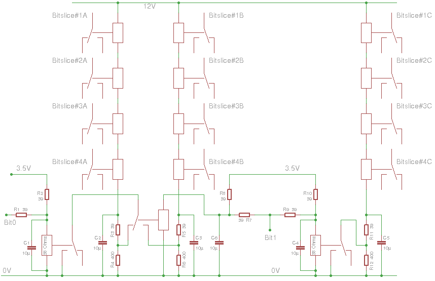
The overhead is because instead of having a MUX2 tree, we simply use N relays to connect one output to the read "bus". So for 8 register as currently envisioned, there will be 8 relays per selector (instead of 7). Those relays will in turn be driven by other relays (the dreaded control signal fanout trees) which are not significantly larger than in the precedent version.
For a 16-bits ALU, there is a 2-level driver tree. Each register is split into 4-bits nibble with shared control lines (with a 10-12V power supply). They are in turn driven by a selector (inverted MUX) powered by the 10-12V supply.
The trouble is basic electromechanics : there is no garantee of a break-before-make on the data output and there are good chances of transient short circuits.
The original MUX tree approach garantees that there is no contact between the Vcc and 0V. Paralleled relays create the corner case where one switches some data that is 0V while another relays is still switching Vcc.
One solution is to add protection resistors on Vcc and 0V. This resistor is needed anyway futher down the signal path.
The other solution is to work with a different logic level : only 0V is switched, otherwise left dangling. This becomes a large "wired-or" network (à la TTL and open collector). No risk of shorts but the level must be restored so a "buffer" stage is required, drawing 1 relay power unit, added to the already constant unit to select one register. The load is pretty constant now, instead of jumping from 0 to 3 all the time. Which approach is better, since the averages are equivalent again ?
Another concern is the latency of the control signal tree: 2 relays-times, with potentially small discrepancies between different branches. Driving 16 relays at once is quite a challenge, no ?
Each coil uses a bit more than 2V so at least 36V is required but standard voltages 24V and 48V are easier to find. I want to avoid high voltages, by the way, and I have some 24V units. 8 coils will need about 20V, which can be obtained by under-volting the PSU (with the tuning pot).
The relays are rated for 100V and 100mA: 2 paralllel strings of 8 coils will draw at least 120mA so an additional 20mA must be drained (through a resistor).
In the log Pre-Biased, or Hysteresis Relay Logic, I see that some, but few, relays require about 60mA, 20% more than the others. These could be "binned" before assembly to save a bit of energy. I'll probably have to build a custom version of @matseng's #ReTest - Relay timing tester
-
Register set update
10/01/2016 at 16:31 • 0 commentsConstruction of one bit of the register set is looking good. I made several adjustments to the original design:
- A separate power supply for the latches and the output.
First reason is to prevent current spikes (during switching) to affect the stored value. A series resistor and a capacitor reduce the susceptibility to electric intererence.
Second reason is that I may want to drive the output with a higher voltage to increase the fanout.
It makes the overall design a bit more complex but a bit safer too. - I use old green LEDs to show the state of one latch. Each draws only 20mA instead of 50mA for the Glühbirnchen. This again increases fanout.
- Added series resistors for the latch inputs.
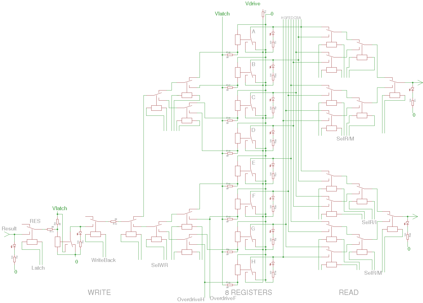
- Each relay has their own driving pin. Yes, that's a LOT of signals to drive and wire. However it should reduce the overall power consumption because only the required relay is energised. There are 21 MUX2 for the register set read and write, and at most 9 will be energised instead of 2.5× more. Of course it increases the complexity of the driving logic but it's already covered in a previous log.
- The input of two of the latches is directly accessed so the register value can be overdriven by external circuits, in particular for memory read (during the latch cycle, to prevent conflicts with the writeback cycle).
![]()
For each bitslice module, I have selected a 2×40 pins header. Most of these pins are used for the MUX. There should be enough pins left for the ALU.
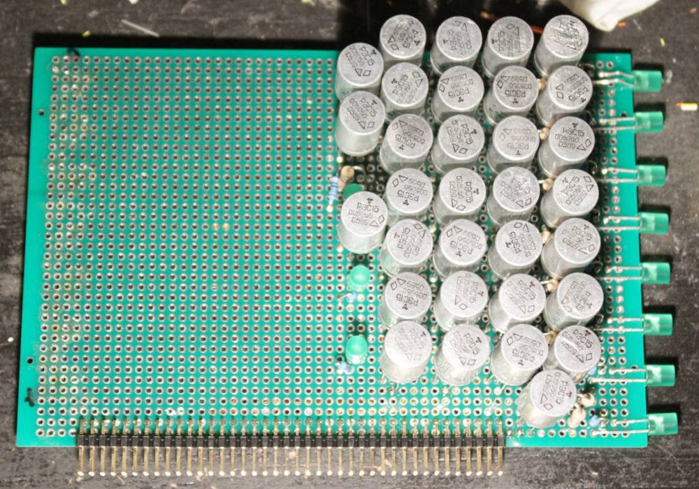
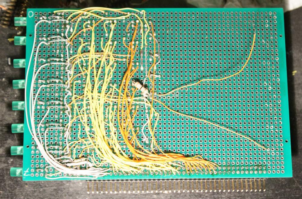
And here you can see 32 relays in all their glory, taking one half of a 160×100mm protoboard:
![]()
![]()
The control circuits will be pretty crazy too... I'm also building a carrier board/backplane to distribute all the contro signals.
Note: on this circuit I didn't manage the Vlatch and Vdrive correctly, the idea came after I soldered all the latches... So I split the 0V rail. The final version will have a split V+ but it will be "mostly compatible", at least for the connector, because V+ and 0V use 2 pins each. It's then a question of which pair to split.
Here I try to transcribe the connector's pinout:
Function pin# pin# Function 0V latch 1 2 0V drive V+ latch 3 4 V+ drive H (R7 out) 5 6 G (R6 out) F (R5 out) 7 8 E (R4 out) D (R3 out) 9 10 C (R2 out) B (R1 out) 11 12 A (R0 out) Sel1 13 14 Sel1 (return) Sel1 15 16 Sel1 (return) Sel1 17 18 Sel1 (return) Sel1 19 20 Sel1 (return) Sel1 21 22 Sel1 (return) Sel1 23 24 Sel1 (return) Sel1 25 26 Sel1 (return) OverwriteH 27 28 Sel1 out Sel2 29 30 Sel2 (return) Sel2 31 32 Sel2 (return) Sel2 33 34 Sel2 (return) Sel2 35 36 Sel2 (return) Sel2 37 38 Sel2 (return) Sel2 39 40 Sel2 (return) Sel2 41 42 Sel2 (return) OverwriteF 43 44 Sel2 out SelWr 45 46 SelWr (return) SelWr 47 48 SelWr (return) SelWr 49 50 SelWr (return) SelWr 51 52 SelWr (return) SelWr 53 54 SelWr (return) SelWr 55 56 SelWr (return) SelWr 57 58 SelWr (return) (0V?) 59 60 Result (WriteIn) Latch 61 62 Latch (return) WriteBack 63 64 WriteBack (return) 65 66 67 68 69 70 71 72 73 74 75 76 77 78 79 80 Only 8 pairs left...
- 2 pairs : Cin-Cou, /Cin-/Cout
- 2 pairs : F0, F1, F2, F3 (ALU)
- 1 pair : Carry enable (+return)
I can still add 4 pairs but it will be pretty delicate.
Yes, splitting the supply rail is a requirement. Apparently the best working voltage for Vlatch is in the range 3.2V-3.5V and could vary from board to board. A 3.3V regulator would fit...
- A separate power supply for the latches and the output.
-
8 registers
09/25/2016 at 02:16 • 0 commentsI have decided to increase the number of registers to 8.
This is justified by a few choices and enhancements. The first being that I'll map two memory spaces to the new registers, so they are not really registers. OK, they are, now, but they will be rewired, and the necessary MUX would have been put somewhere else otherwise so this is not really a significant increase in complexity or relay count. Actually, it removes the MUX that selects the operands (either the register or the external data, which is either an immediate from the instruction word, or memory).
The trick is that the constants will be injected at the ALU level with the ROP2 logic unit :-) so 2 MUX are "saved".
The relay count is increased to 32, including the result latch. This last part is pretty critical because the bounces lasts at least 2ms so the capacitor trick doesn't work. A 3-phases system is necessary:
- acquire/latch the result data (at least 2ms to stabilise the latch bit)
In fact this also corresponds to the ALU delay, as well as the time to switch the result MUX8. - turn the latch signal off (at least 2ms more). The result MUX8 must be stable by now.
- send the WriteBack signal, at least 5ms (2ms for the WB relay to switch then 2ms for the register latch to switch too)
In case writeback is not required (for comparisons, maybe ?) then some of these cycles can be saved and the instruction can run faster. If the result register is different from both operand registers, the latch can be short-ciruited as well !
32×16=512 relays... things get serious, and power consumption too ! A lot of power is used by the MUX8s and their consumption must be reduced as much as possible. See the previous logs about that. About 24 control signals must be driven....
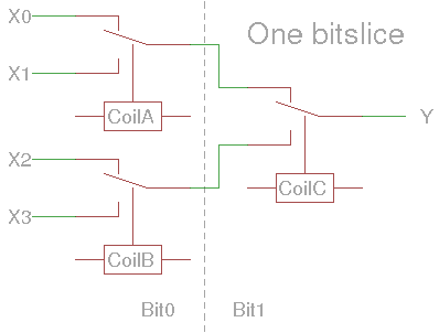
I'll try to build a prototype of the following circuit, which is one bitslice:
![]()
It's going to be a pretty cute 8×4 array of cylinders :-D
The 8 latch relays will be on the outer edge of the board, to expose their value with a LED. The Glühbirnchen would be much better (visually) but they consume 50mA and already eat most of the switching capacity of the relays (100mA) and I still am not sure about the fanout in the ALU. In the beginning I'll use normal LEDs (green ?) and later, a set of 8 #DYPLED :-)
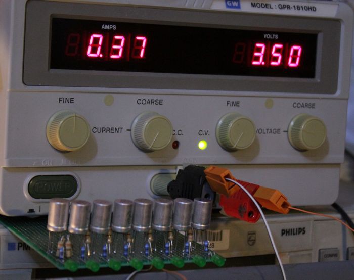
I couldn't wait and I started soldering stuff. Good news : 8 relays fit into 100mm :-)Power for 8 latches is 0.37A×3.5V=1.3W. Yes, more than 1W per byte :-D
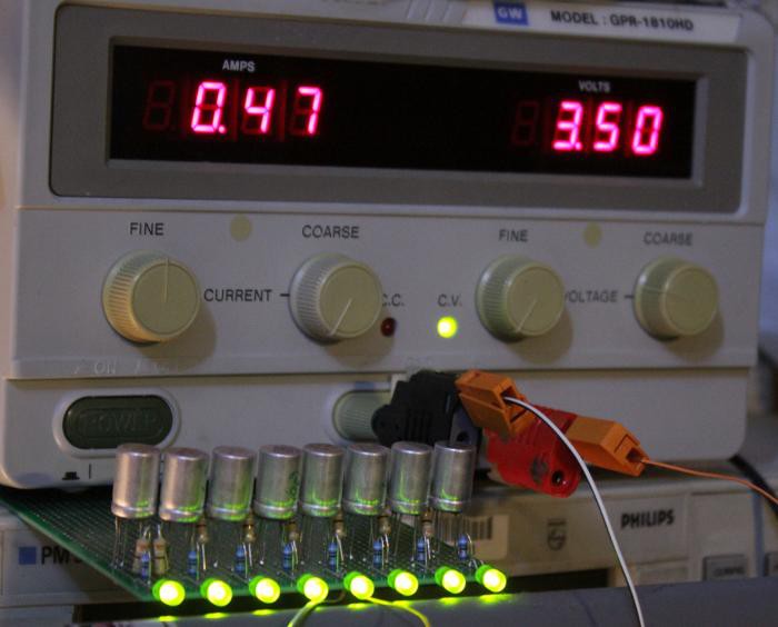
And this is when the latches are cleared because the LEDs draw some current too:![]()
![]()
Yup, that's 1.6W :-D A whole set (16×8) will draw 27W.
No wonder this technology is not used anymore.
The first LED turns on at 3.6V and the first LED turns off at 2.55V.
- acquire/latch the result data (at least 2ms to stabilise the latch bit)
-
Majority gate with PBRL
09/24/2016 at 02:39 • 0 commentsStill reading Dieter Müller's articles...
The idea of the majority gate designed with parallel resistors (or a crude DAC ?) is too tempting and I understand his fascination. Looking at this diagram:
![]()
This could be translated into ECL or resistor-relay logic almost directly !
Now the question is: could this work with my pre-biased logic cell and what is the value of the parallel resistors ?
20160925: Hysteresis would kill the design but all hope is not lost. Switching from a "DAC" to a "current adder" could be a solution. Diodes let the current go through one direction and this is great because the relay is mostly a current-driven device.
However, according to this log, the coil current must be >= 60mA to turn the relay on, and less than 25mA to turn it back off. The Hysteresis is way too high to make the current adder useful. Is there a way to reduce a relay's hysteresis ?
-
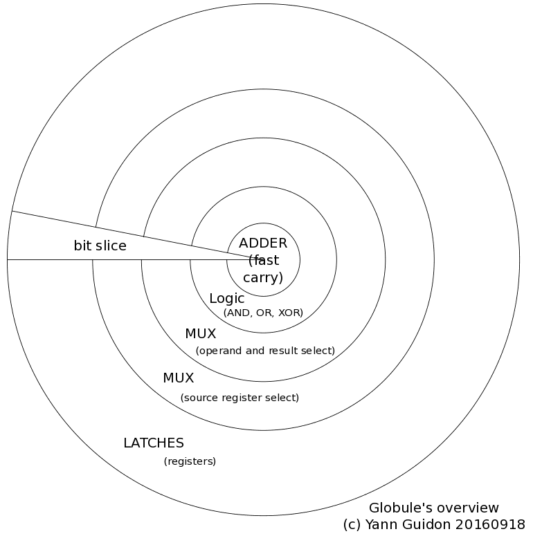
A modest Globule proposal
09/18/2016 at 15:01 • 0 commentsAfter a week of thinking about all the aspect of this "AMBAP", I realise that it is much more than what I thought.
It started as a toy idea that needed to be convenient, conceptually minimalist yet self-sufficient for making a reasonably RISC-y machine.
To my surprise, along the way, it brings a really minimal critical dapatath. This translates in raw speed. This thing can go fast and I'll see how fast I can go with it, either with relays, germanium or silicium, ECL or TTL :-)
Each bitslice contains all the necessary elementary parts of a computer : you can make it with the usual gates AND, OR, XOR, MUX and latch. It is not just educational : it also reduces the burden of the design and analysis of the ALU and register set. Design for one bit and you have the behaviour of all the bits, no uncertainty !
But there is more to this approach, which brings a new perspective and more appeal. The bitslice point of view has reduced the absolute critical datapath to this of the adder's carry chain. This means that it is the only aspect to optimise and the rest can be organised around it.
This is a major thing for ASICs. In integrated circuits (CMOS), wiring delays are as prominent as gate delays. So this single optimisation criterion becomes a natural geometric constraint. The high-speed part (the adder) becomes the center of the unit, to keep wires short, and the other gates are litterally spread around this core.
Since a circle is highly symmetrical and all the bits are identical, the design is extremely simple and all you have to design is one slice, not like a slice of bread but a slice of pie :-)
![]()
Asymptotically, when the number of bits increases, the angle of the pie slice nears 0 and becomes almost flat.
Another remark is that this also works naturally well with fanout trees : there are many control signals to broadcast throughout the whole unit and the centrally symmetric design is perfect!
Of course, I still have to analyse how to optimise the adder's datapath. @roelh has provided some important insight in the comments of the project :-)
But so far, I can analyse the design with relays, transistors, ICs, and I have suitable FPGA to test the integrated version. I still use the old ProASIC3 because its granularity is close to the logic gates we use, giving a pretty accurate feeling of what would happen in a full custon ASIC.
I wasn't aiming at speed but it's so fast I can't go any faster. Maybe add a pipeline gate here or there. It is so minimalistic that it's worthless to include pipeline bypass. More complex operations (multiply and barrel shifter) must be performed by external units, in multi-cycle fashion.
The big issue remains: the control lines, with many very high fanout, consume power and wires.
Now, since the datapath is looking totally different, I found a name for the ALU+REG-datapath: "Globule". In a given implementation, you could use one or several globules for increased ILP :-)
There are many benefits of the approach I am developing now. They will heavily influence the design of the #YASEP Yet Another Small Embedded Processor and #F-CPU. But more than that: you can just forget about the canonical RISC pipeline of Patterson and Hennessy. Just design one bit, copy-paste-rotate, and you have your datapath. All the fun stuff will now be relegated to designing your instruction set and scheduling :-)
-
My first Pre-Biased Relay Logic gates
09/12/2016 at 19:56 • 0 commentsAfter the theory, let's practice :-)
I simply wired the simple gate as designed yesterday and it runs smoothly:
![]()
![]()
So I can hear the characteristic click of the relay, with a sound that differs from the switche's.
But I don't learn anything...
Or did I ?
It works well at 3.15V then ceases after a few minutes.
3.30V, OK.Then now it's 3.40V...
The coil is constantly energised and power is dissipated in the copper coil, which changes resistance. This increases the working voltage... Fortunately, I'll use adjustable POL regulators :-)
So before examining the dynamic behaviour, let's make sure the thermal behaviour is good.
Let's say that 3.5V is a good compromise.
With the pulse generator, I'm able to drive one relay coil with a lozange waveform. In turn, this drives the slave coil (#1) with the 3.5V square waveform.
The master coil behaves well and I could push the pair to more than 25Hz. However the waveform at the coil of the slave is quite dirty, with and without the parallel 100n capacitor. I don't see overshoot but a lot of bouncing...
Pushing to 50Hz with a triangle waveform, the master still works well but the output is very bouncy. This sort of relay can switch very fast but the outputs will become very dirty in comparison. Capacitors have no apparent influence on the waveforms so let's just get rid of them.
![]()
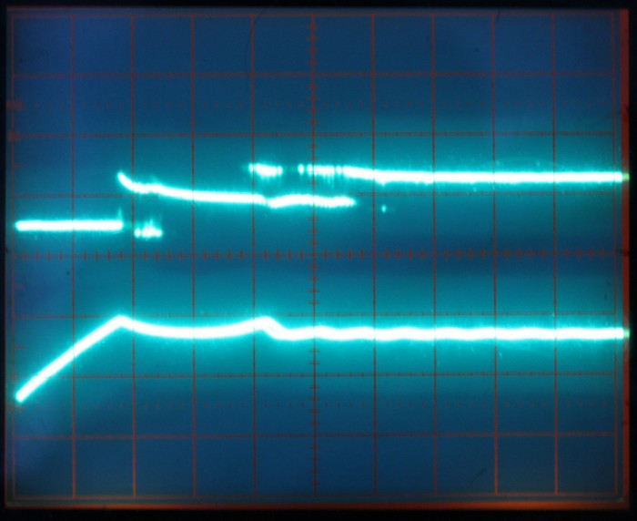
A 4.7µF tantalum across the slave's coil smoothes the waveform enough to become quite recognizable. No need of a parallel capacitor with the liaison resistor. The 4.7µF reduces the junk on the coil (a little bit), not the actual bounces, so the EM emissions are still be quite high. 10µF would be better but 47µF is too much.
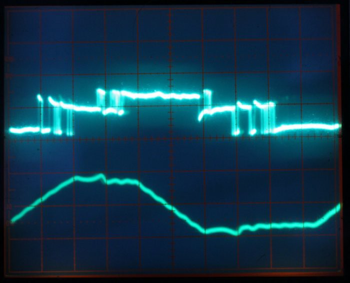
Below: coil voltage without cap : (1V/div, 1ms/div, lower trace is the control voltage of the master relay, with 1/2ms chopped by the trigger at 0.5V)
![]()
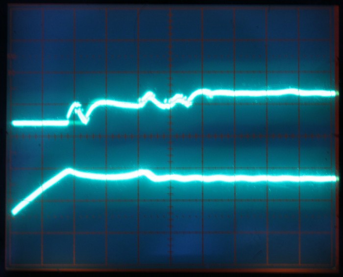
Below, with 4.7µF tantalum:
(looks a bit better)I have also measured something else : the signal-to-contact latency is about 2ms (with a ramped control so it might be a bit shorter) then the ringing lasts about 4ms. This gives an upper bound for the circuit's speed. I must measure the actual delay with more relays in a chain :-)![]()
When pushed to 50Hs, the cycle time is 20ms, with 10ms high and 10ms low. The coil voltage looks like that:
![]()
Compare to the unfiltered signal (no capacitor, and the lower trace is the clean 50Hz ramped signal from my generator):
![]()
The transients last 4ms (2ms/div).
The thermal drift does not exceed 3.5V too much so that's reassuring.But the protoboard's bad contacts make the circuit very unstable, I must solder it...Now, considering that the relays will draw 50mA (in average) and there will be at least 30 per bit-slice module, the expected power consumption of the bitslice is around 1.5A ! Let's round it up to 2A.
For 8 bits, that's 16A.
For 16 bits, 32A at 3.5V, or approximately 100W, and there is still no control or memory circuit !
It is obvious that half of the relays of the bitslice (16 at least) are MUX relays that are completely controlled by the outside circuits, all in parallel. They will be wired in series to reduce the power losses, and they will not use PBRL, but swing between 20 and 60mA.
![]()
(the resistor values are NOT experimentally checked yet...)
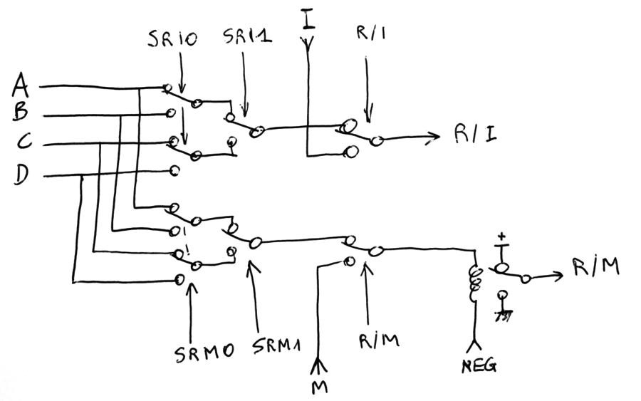
Furthermore, there are several multi-level MUX and DEMUX but only one path is taken so there are cases where one first-order MUX (controlled by bit0) provides useless data. These MUX can be left at rest.
![]()
The above diagram shows that at most 2 relays need to be energised. This is solved by the circuit below:
![]()
Bt1 controls which branch gets more current, with the help of a 3rd relay that MUXes either of the first levels signals.
And now that I think about the bounces, I realise that the latch won't work well... The capacitor will receive a lot of noise, unless it's a very high capacity (>100µF) with a series resistance.
A two-stage relay latch, with correctly spaced pulses (with a 10ms interval between them), is necessary. The test at 50Hz shows that 10ms pulses are possible but the control signal must be clean...
20161107: The above assertion must be carefully examined. A single clock source is better than a sequence... The new project #ReTest-RPi will clarify this.
-
Pre-Biased, or Hysteresis Relay Logic
09/12/2016 at 00:36 • 25 commentsPLEASE tell me that this system already exits in the wild (or has existed) because it makes me feel uncomfortable to reinvent an ancient technology...
Borrowing ideas from ECL (non-saturated transistor logic) and from the single-relay flip-flop (using internal hysteresis), let's now play with non-saturated relay coils :-)
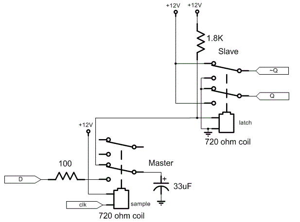
![]() Relays have hysteresis. This is used by the flip-flop of the register set (see the principle, above, from http://relaysbc.sourceforge.net/circuits.html). But this could also be used for the logic, for these great reasons:
Relays have hysteresis. This is used by the flip-flop of the register set (see the principle, above, from http://relaysbc.sourceforge.net/circuits.html). But this could also be used for the logic, for these great reasons:
- Faster switching because less voltage difference
- more controlled average consumption
- no freewheel diode
- less current in the signals, increasing fanout
Let's simply start with the flip-flop and characterise the relay, to compute the right resistors/supply voltage.
I took 10 RES15 from their box and measured the following:
# coil
(Ω)ON
(V)
ON
(mA)
OFF
(V)
OFF
(mA)
1 38.4 1.83 48.5 1.15 30 2 38.2 1.92 50 1.06 27.6 3 38.9 2.05 50.4 1.05 26 4 36.9 2 52 1.2 31 5 38.2 2.05 52 1.18 30 6 37.8 2.30 59 1.43 36 7 37.4 2.26 59 1.27 33 8 37.6 1.81 46.8 1.30 33.6 9 37.3 1.82 47.5 1.20 31.2 10 36.7 1.77 46.8 1.12 29.6 avg. 37.7 1.98 51.2 1.19 30.8 (note: the voltages might be slightly exagerated because the ampmeter was in series with the PSU, but the current seems to be the most important and stable value. Mechanical wear and temperature might also affect these values)..
The mid-range seems to be
- (51.2+30.8)/2 = 41mA
- (1.98+1.19)/2 = 1.58V
MinVon=1.77V, 0.19mV margin
MaxVoff=1.43V, 0.15mV margin
The deviation of the resistance is quite low, compared to the triggering values. 5% resistors will work...
What is the highest supply voltage that a 1/4W pull-up resistor can stand ?
U=P/I = 0.25W/0.041 = 6.1V (to be added to the 1.58V average).
With a 5V power supply for a latch, the resistor will dissipate 0.041*(5-1.58)=0.14W
That resistor will be R=U/I= 83Ω
This is close to the standard value 82Ω, but what supply voltage is required for a lower, 50Ω resistor ?
U=R×I = (50+37.7)*.041= 3.6V
The voltage swing now must considered:
- MaxVon=2.3V, margin: 0.72V
- MaxIon=59mA, margin: 18mA
- MinVoff=1.06, margin: 0.52V
- MinIoff=26mA, margin=15mA
A relay must pulse about 20mA to change the state of the slave coil. The system is more sensitive so the wasted energy in the bias resistor is compensated by the lower switched current (20mA instead of 60mA) which increases the fanout ! (going from barely 2 to 100/20=5 coils).
My stock has a quantity of 91Ω and 47Ω resistors.
- (47+37.7)*.041= 3.47V
- (91+37.7)*.041= 5.27V
These values are "close enough" to the standard 3.3V and 5V commonly found in power supplies, with a little offset (0.2V or 0.3V), which can be adjusted by a pot in several types of PSU.
The best choice seems to be a 3.5V supply. Not just because less power is lost in the pull-up resistor but more importantly because it is closer to 1.58×2=3.16V so a resistor tied to 0V or 3.5V will have roughly the same perturbation current.
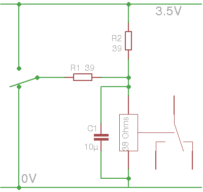
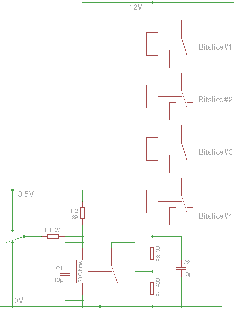
OK now it gets fun: I just found a box of 1K 39Ω resistors. Which is, by coincidence, very close to the coil's resistance ! Calculations will become very simple :-)
At 39Ω and 41mA, the voltage is 3.15V.
![]()
- When the left-hand switch is open, there is a 41mA current flowing through the coil. The previous state is preserved.
- When the switch is connected to 0V, the capacitor C1 will act as a short to 0V and both R2 and the coil's reverse surge will try to charge it. However there is a parallel resistor R1 of same value that will 1) discharge C1 (during times of bounces) and 2) keep the coil's voltage low.
- When the switch is connected to +3.15V, the same will happen but with reversed polarity.
Increasing C1 will help increase the value of R1 (and increase fanout). But with R1=R2=Rcoil, we have Vcoil = 1/3 or 2/3 Vp, or 1.05V and 2.10V. The capacitor is required to give the "extra kick" for the relays that trigger beyond these limits.
The total current, when R1 is connected to 0 or 3.15, is: 3.15/(39+(39/2))=53mA. Since Rcoil=R2, the current in R1 is half the total current, or 53mA/2=26mA. OK that's not the expected 20mA but we still have a fanout of 100/26=4 relays. Good !
The value of C1 is arbitrary and should be tested, for example at high frequency, since I have tested the relays near DC, with very slow ramps, and there could be some magnetic remanence.
Now, I haven't solved the problem of the XOR, and some AND situations, where both sides of the coil are switched.
-
SPDT version
09/10/2016 at 23:22 • 0 commentsIf you have followed the #SPDT16: 16-bits arithmetic unit with relays project, you will recognise a lot of elements. Actually, most of the important details have been solved :-)
The first part of the datapath is incredibly obvious with SPDT relays, because they are natural multiplexers. Even the XOR uses a single relay:
![]()
9 relays so far :-)
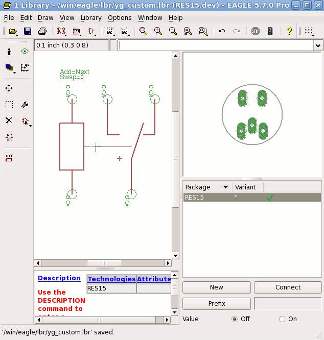
It's so simple that I had to make a component for Eagle:
![]()
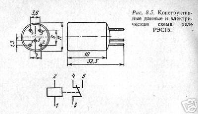
I have reused the little data I got from the seller:
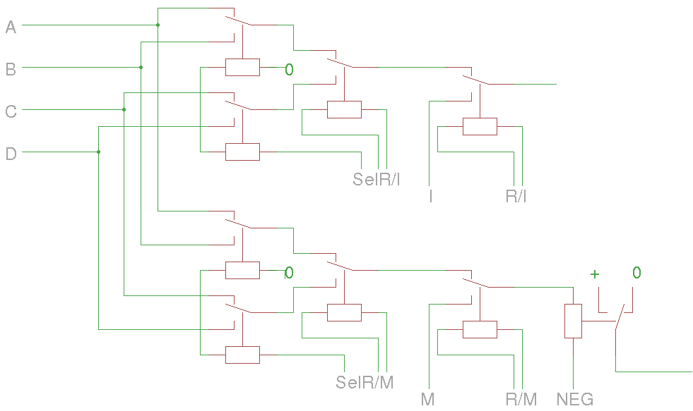
![]() Now I can proceed with the rest.
Now I can proceed with the rest.![]()
Adding the write logic and the latches is pretty easy.
Parts count : 17 relays "only" :-) Asymptotically, the parts cost is around 4 relays/bit (1 latch, two mux, one demux) (+4-3). I use the "hysteresis" approach for the latch, where a resistor is chosen to provide just enough current to keep the latch either ON or OFF.
![]()
I can already see that the control signals will drive A LOT of relays simultaneously. Considering the rather low current handling capability of the RES15, I believe that it is necessary to use higher voltages when the fanout is high. The relay's contacts will be stressed so current limiting resistors, capacitors and overshoot protection diodes must be designed.
I think that running the high fanout signals at 12V is reasonable, this could control about 6 or 7 coils in series. A 24V PSU is also possible for more fanout. Then, DC/DC will step this down to about 5V for the "logic" signals.
From the seller's description:
> Coil : 2.8V 60mA
> Switching voltage up to 150V 100mAThe coil's characteristics have been studied before (and are more reasonable) but this means that at most 2 relays can be driven in parallel... The backplane will have to take this into account, when it connects the coils in parallel and series. A multi-level amplification tree must also be used.
Furthermore, to reduce switching times, the coil's energy must be released/dissipated quickly. Different working voltages would make the coil's energy swing around the hysteresis point...
This will be a fancy and noisy heater for this winter.
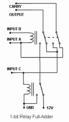
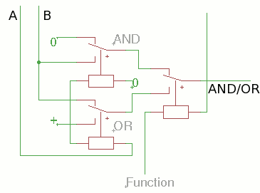
The rest ot the datapath is pretty simple and is centered aroud a full-adder circuit as described at Rationale and general idea. It takes only 3 SPDT to compute one bit, as explained at Basic Relay Computer where you can find the following drawing:
![]()
More relay tricks have been found at http://relaysbc.sourceforge.net/circuits.html
The above circuit computes the XOR between A and B but the output is also influenced by input C. Thus the normal output can't be directly used as a XOR, unless C can be disabled and kept low.
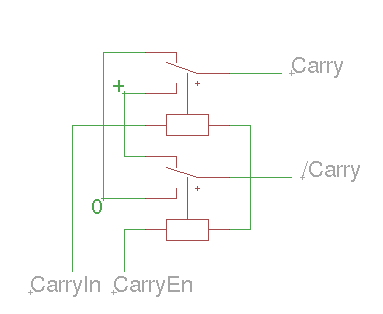
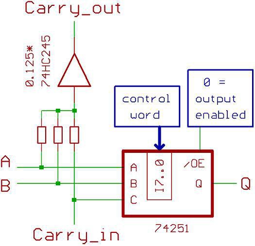
Merging the XOR and ADD signals saves one MUX input and one relay, though disabling the carry chain also consumes one relay... One stone, two birds : I add a "Carry enable" that is also a buffer that regenerates the Carry signal. This is necessary because the "input C" will progressively get more and more current, from all the inverting relays it will find along the carry chain...
![]()
CarryEn will get a large load but will only switch to 0V, it might be handled by the control/backplane with a fanout tree.
Logc is easy as well and uses 3 relays:
![]()
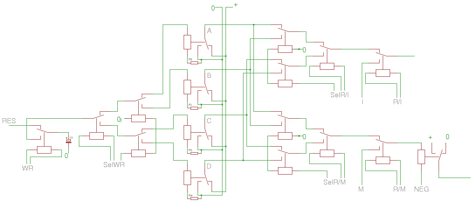
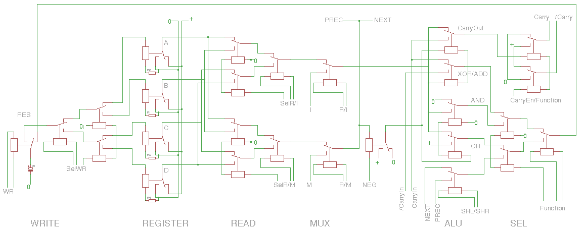
Overall the single-bit datapath uses 27 SPDT relays :-)
![]()
Somehow I managed to reduce the result's MUX8 down to a MUX4, though many sub-functions have been moved/transformed upstream. I'm quite proud of this achievement :-)
Note : I could have replaced the OR with diodes but... no. Because there are design rules that force me to be careful about driving strength and current direction. I would have had to add an amplifying relay in the critical datapath.
27 relays on the bitslice module, plus a few amplifiers on the backplane, let's say 30 relays/bit.
- 8 bits wide : 240 relays
- 10 bits wide : 300 relays
- 12 bits wide : 360 relays
- 16 bits wide : 480 relays
This is very tempting :-)
8 bits or 10 bits is reasonable, 12 bits will make a nice quad-octal (or tri-hexadecimal) machine :-D
However at 16 bits, the carry chain will use most of the cycle time. 16 bits is within my reach but might be an extra challenge...
So let's just try it as it is, evaluate the issues (delays, consumption, fanout, etc.) and see if the above design really needs any enhancement :-)
AMBAP: A Modest Bitslice Architecture Proposal
Trying to unify and simplify a minimal architecture for various implementation technologies...


 Relays have hysteresis. This is used by the flip-flop of the register set (see the principle, above, from
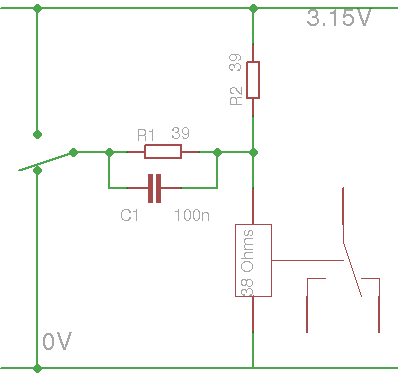
 Now I can proceed with the rest.