Close
0%
0%

Wireless PIR's + Controller for PTZ Camera

A cheap open-source 4ch wireless ptz alarm controller

Similar projects worth following
I have a ptz camera installed at my house and do not want wires running all the way around my garden and really didn't want to pay a lot of money.
My camera only has 4 alarms that i can use, but the system can run upto 6 at the moment.
I originally started with a cheap household pir hooked upto an arduino but have just completed my first fully wireless pir complete with a charger circuit.
I have never coded anything before but have been wanting to start the arduiuno for over a year now, So obviously my code does have its problems I'm using NRF24L01 but really need to figure out how to put my NRF24L01 into standy when not sensing anything. also all my PIR's are on the same channel, which doesn't seem to cause to much of a problem yet.

The good thing about this project is that it does not have to be just used with cctv cameras could also be used for many other applications.

The current state of product at moment is as follows,

The main controller

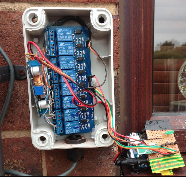
- Operates 4 relay outputs. The camera has a common wire and 4 alarm wires. i wire the common wire to common of all relays then each alarm wire to the corresponding NO contact on the relay.

- Very easily upgradable to more alarm outputs

-

The PIR version. 1

- Can select which alarm output 1-4

- Only lasts a week per charge (OLD CODE)  not tried the new stuff yet. 

The PIR version. 2

- Solar powered cell charger

- Can select which alarm output 1-4

I am starting to look around for custom components to build the pit micro controller from scratch been looking at the aTtiny84

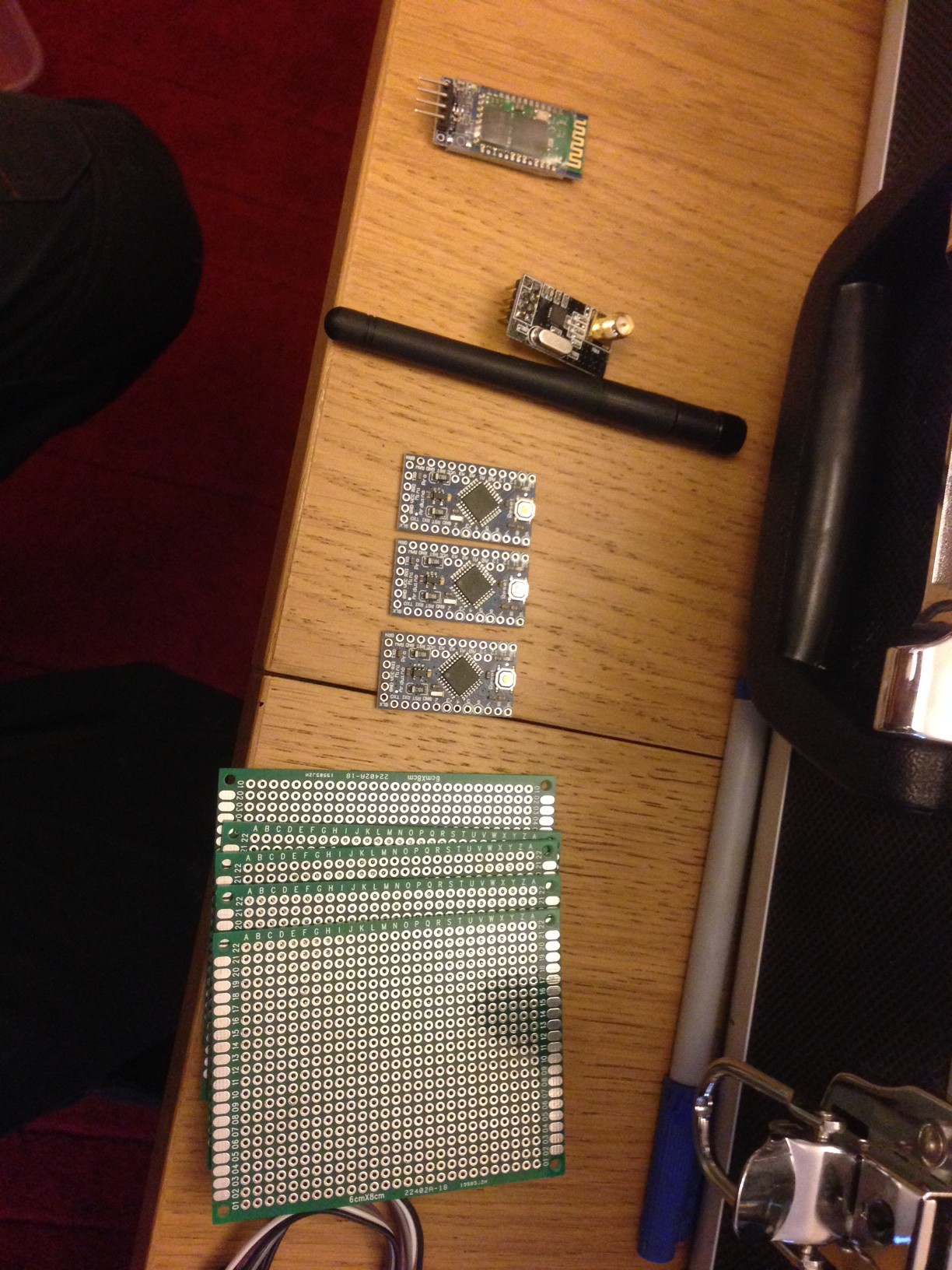
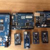
  • 1 × Arduino pro mini 3v 8mhz Atmega328 This is for the PIR
  • 1 × 5v PIR module This is for the PIR, Item model number: ST-ZV390-ZX (amazon)
  • 5 × NPN Transistor I used a 2n3904 (what i have lying around) used for PIR
  • 2 × Breadboard used for the PIR and Controller
  • 5 × LED various flavours Used for both PIR and controller

View all 6 components

  • Version 0.3

    dannyritchie07/14/2014 at 08:42 0 comments

    Finally got around to updating the firmware on on the controller and PIR's. So let's hope we don't have to any problems as this is the first time the completely rewritten source code has been in the real world. Mi need to update my Dropbox folder as that only has version 02. 

  • Tidying page up. This was posted on the details should of been a project log

    dannyritchie07/06/2014 at 15:26 0 comments

    At the moment i only have one 3v3 8mhz arduino mini pro so only have one complete PIR. I found using these made sense as the NRF24 module runs at 3v3.

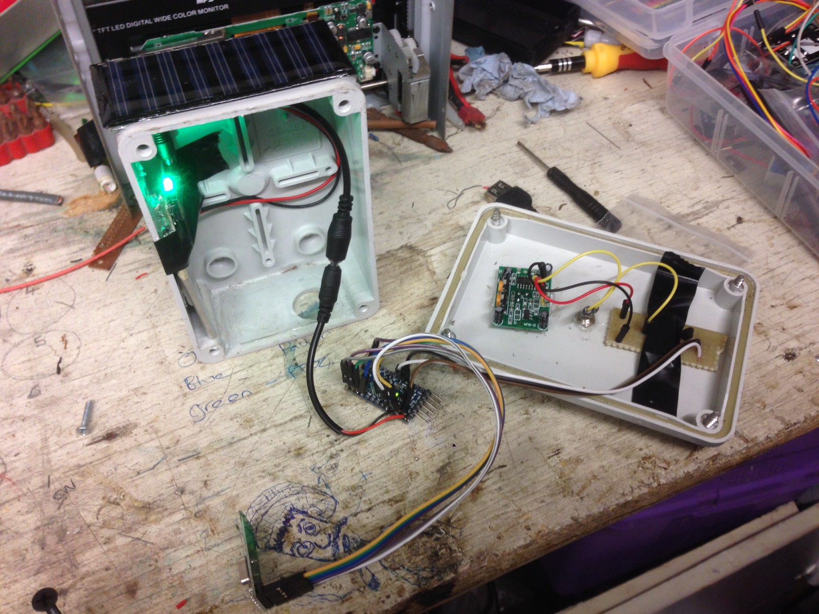
    The housing on the current one is from a faulty wired pir, I removed the golf ball like lens off my pir module. I do plan on keeping the golf ball cover on future models and make my own housings.

    Heres a short video of two prototype pirs controlling a couple of LED's

    Here's a new video of a 4ch remote i made up for testing the main receiver.

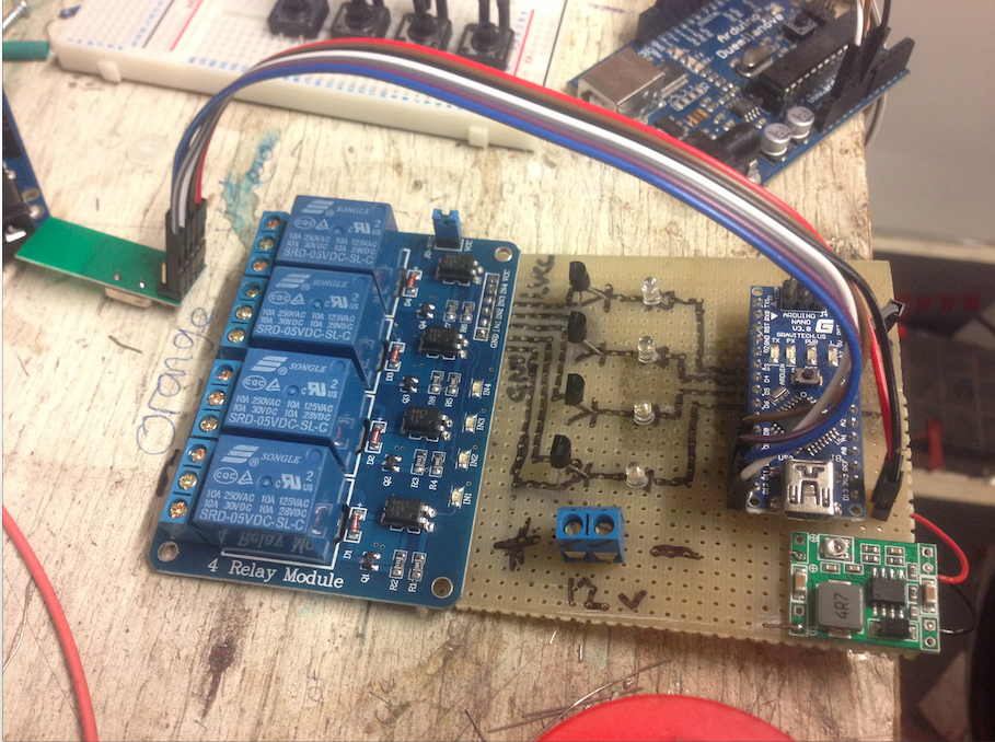
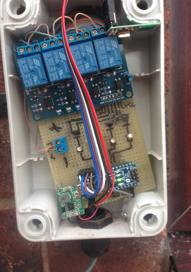
    Here's a Photo of the main controller box, I've just received my 4ch relay but not had time to fit it yet, Board on the left is a step down power supply as the camera is using 24vdc. The relay module for some reason uses a low as on and high off. I have made a temp proto shield with the outputs going through some NPN transistors i had laying around

  • (edited) Updated the source code

    dannyritchie07/05/2014 at 21:52 0 comments

    Not a lot of work done on the hardware side of things this week, But i have completely rewritten the source code for the product. I now have a sketch for the main controller and a separate sketch for the PIR. I was using an Array last time and now have gone for assigning each pin. The source code has no comments as of yet will add them at a later date. 

    On another note the PIR i added a solar panel too is still active.

    Hopefully if i get chance i will create another PIR this weekend see how the system copes with 3.

    The source code has been updated again i seem to be getting a lot better results, I'm currently testing with 2x remotes and 1x controller. I also have a bit better serial output a lot more useful for debugging.

  • We now have a Solar PIR

    dannyritchie06/29/2014 at 16:59 0 comments

    Im just hoping that it will be able to keep the PIR powered all the time now.

  • Finally some post has arrived

    dannyritchie06/29/2014 at 15:09 0 comments

    Finally some of my post has turned up.  Looking forward to adding the new NRF24L01+ with amp to the main controller. plus i can add one of the 3v3 arduinos to external pir which has the duemi. I also have a couple of Solar chargers arrived which will be getting installed to that PIR as well.

    On another note the last project log i entered about adding debounce so the controller will keep the output high while the PIR is active , I think i have sussed it. On my test boards i have set up i can have the sender keep the input HIGH and the controller output stays HIGH. Just need to get code flashed to controller and PIR's to fully test if each PIR can communicate sill.

  • Time to work on some code

    dannyritchie06/23/2014 at 17:08 0 comments

    Back to working away from home so time to work on my code. At the moment when ever  a PIR is triggered the controller will latch a really for a set time if the PIR remains sensing something the controller does not recognise this. Im quite sure that this is because i need to make the PIR thats sending the signal to check to see if the pin is still LOW. I believe that adding debounce (I think) will help with this. Hopefully i have enough parts with me to build a couple test units or testing will have to wait until the weekend.

  • Quick video

    dannyritchie06/22/2014 at 00:28 0 comments

    video of me testing the new controller board before replacing the old model.

  • A bit of tidying.

    dannyritchie06/22/2014 at 00:05 0 comments

    Well decided to tidy up the main controller today lot more happy with it now, Still need waiting for the new NRF24 with external antenna. I also created a second type of PIR this time using the golf ball like lens. On another note i think i am going to try get hold of some solar panels so the PIR's will bell fully self sufficient.

    Heres the new 4ch controller,

    And here it is in the enclosure,

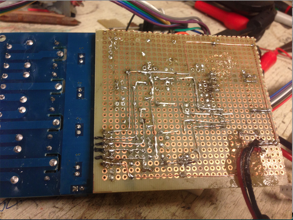
    Heres the back of the panel this is before i added the 24v step down,

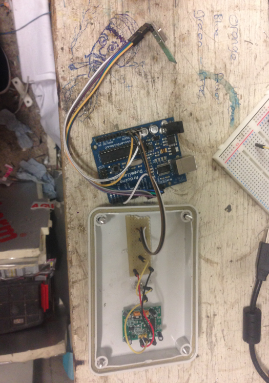
    Heres the insides the of the new PIR, The Duemilanove is temp,

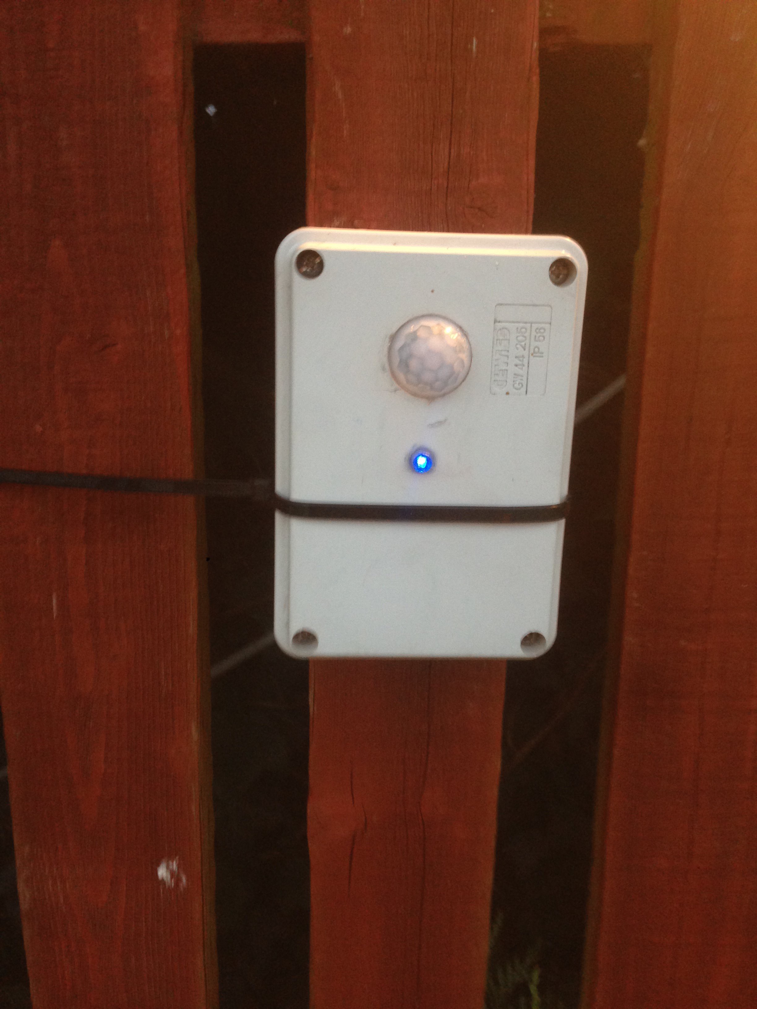
    Here it is mounted on the fence in the garden.

  • Always Waiting

    dannyritchie06/21/2014 at 09:36 0 comments

    Been a quiet week, Still waiting for my 3v3 mini pro's and various other components :)

    As soon as parts arrive i am going to tidy up the controller, I have a decided to add an NRF24L01 with external antenna to the controller. At least while i am waiting for the parts i can work on the code a bit.

    Need to do.

    *Possibly put the NRF24 and arduino to sleep in the PIR's, (Needs testing as i do not want there to be to much of a delay moving the cam.)

    *

    *Possibly have each PIR on it own channel. At the moment they share the same i have two PIR's which seem to be getting along will see what happens when new boards arrive.

    *I need to spend a bit more time R&D existing external security PIRs, (Need to learn to direct the sensor help reduce false detections.)

    *Been thinking of adding a solar panel to the PIR's to help with battery.

    *Start to design a custom board, (First version will be 3v mini pro shield)

View all 9 project logs

  • 1
    Step 1

    For the controller and PIR the NRF24L01 uses the same pins to connect to arduino, 

    Pin connections are,

    - Vcc - 3v3

    - CE - Pin 9

    - CSN - Pin 10

    - SCK - Pin 13

    - MOSI - Pin 11

    - MISO - Pin 12

    - GND - 0v

    - On the controller board you will need to connect to pi A4 to GND

  • 2
    Step 2

    The OUTPUT pins are mapped to the INPUT pins which are

    PIN 2 = INPUT/OUTPUT  1

    PIN 3 = INPUT/OUTPUT  2

    PIN 4 = INPUT/OUTPUT  3

    PIN 5 = INPUT/OUTPUT  4

  • 3
    Step 3

    On the new version of source code i need to add a 10k resistor from arduino INPUT pin to GND on one side of switch and 5v on other side. Before i added the 10k i was getting false readings. I may need to re enable the internal pull-up resistor in the next version of source as on my PIRs i have an NPN which would normally bring the INPUT pin LOW

View all 3 instructions

Enjoy this project?

Share

Discussions

Ron wrote 07/01/2014 at 22:15 point
I am going to follow you on this one, great Project

  Are you sure? yes | no

Adam Fabio wrote 06/19/2014 at 03:58 point
NRF24L01 and a PIR? where do I sign up? Thanks for entering The Hackaday Prize! You've got a great setup for everything from home security to occupancy monitoring and recording there.
Keep the updates coming - we're about to start the community judging!

  Are you sure? yes | no

dannyritchie wrote 06/14/2014 at 23:40 point
That sounds spot on, do you recommend any books that will help with arduino I'm a real NOOB only been coding for arduino for about 3 weeks and not got an other experience with coding. lol. only just learning that i can put arduino into sleepmode. lol

  Are you sure? yes | no

davedarko wrote 06/15/2014 at 10:04 point
I must admit that I never tried that myself but I want to with my sonic screwdriver project. Their website is always a great start point for reading material.

http://playground.arduino.cc/Learning/ArduinoSleepCode

  Are you sure? yes | no

davedarko wrote 06/14/2014 at 23:11 point
if it helps you can check my wristband project for the selection of a channel with dip switches. WIll you use the PIR to switch on the Arduino on an interrupt pin and then turn on the nrf24?

  Are you sure? yes | no

dannyritchie wrote 06/14/2014 at 23:22 point
I was more thinking of just putting the nrf to sleep as with it being for the camera i want to keep it as fast as possible. My goal at the moment would be to try and get at least 3 months per charge. i have thought about adding a solar charger which could solve my problem.

  Are you sure? yes | no

davedarko wrote 06/14/2014 at 23:34 point
You should test the interrupt part for speed since this would allow you to put your arduino into sleepmode, too.

  Are you sure? yes | no

Similar Projects

Does this project spark your interest?

Become a member to follow this project and never miss any updates