To keep this simple I'm going to use some existing designs that are proven to work.
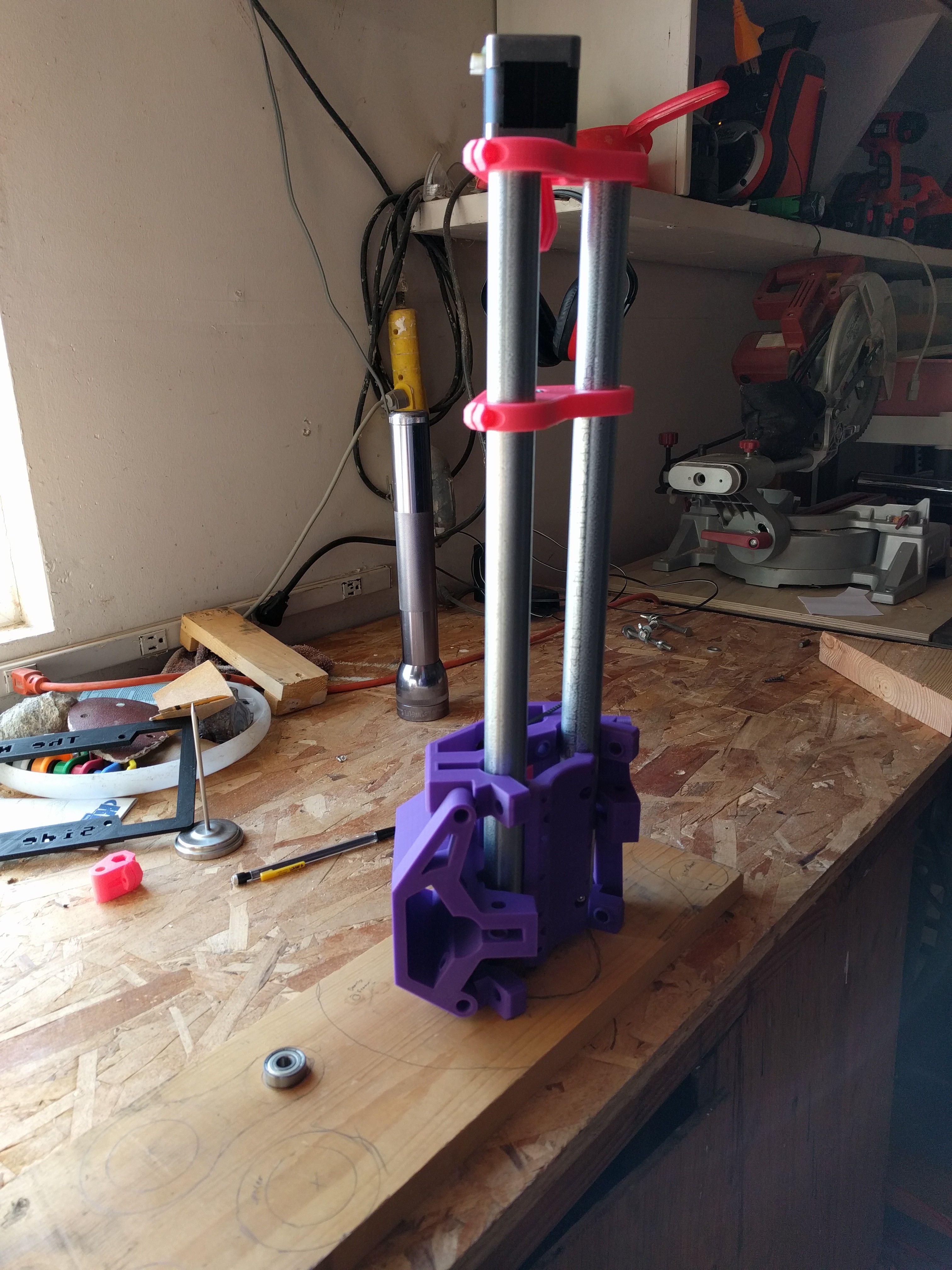
The Z-axis will be copied from the Mostly Printed CNC from http://www.vicious1.com/. It uses 3/4 inch conduit, screw drive and standard nema 76oz motor.
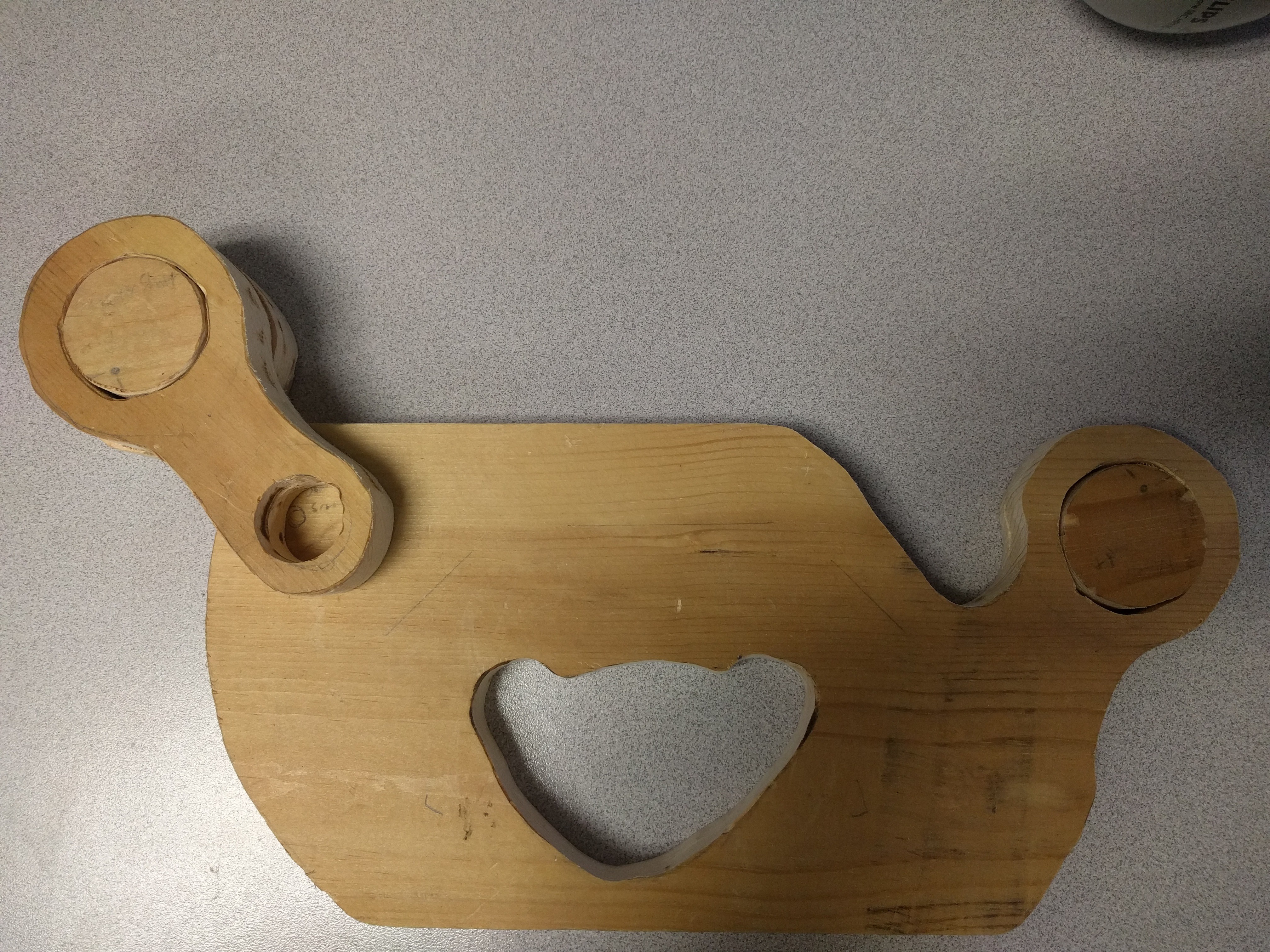
Next we are going to mount that to the same system that was used by the shaper to move the CNC (see image posted by hackaday.com). Most of the parts around this will be cut out of the 6x8 plywood
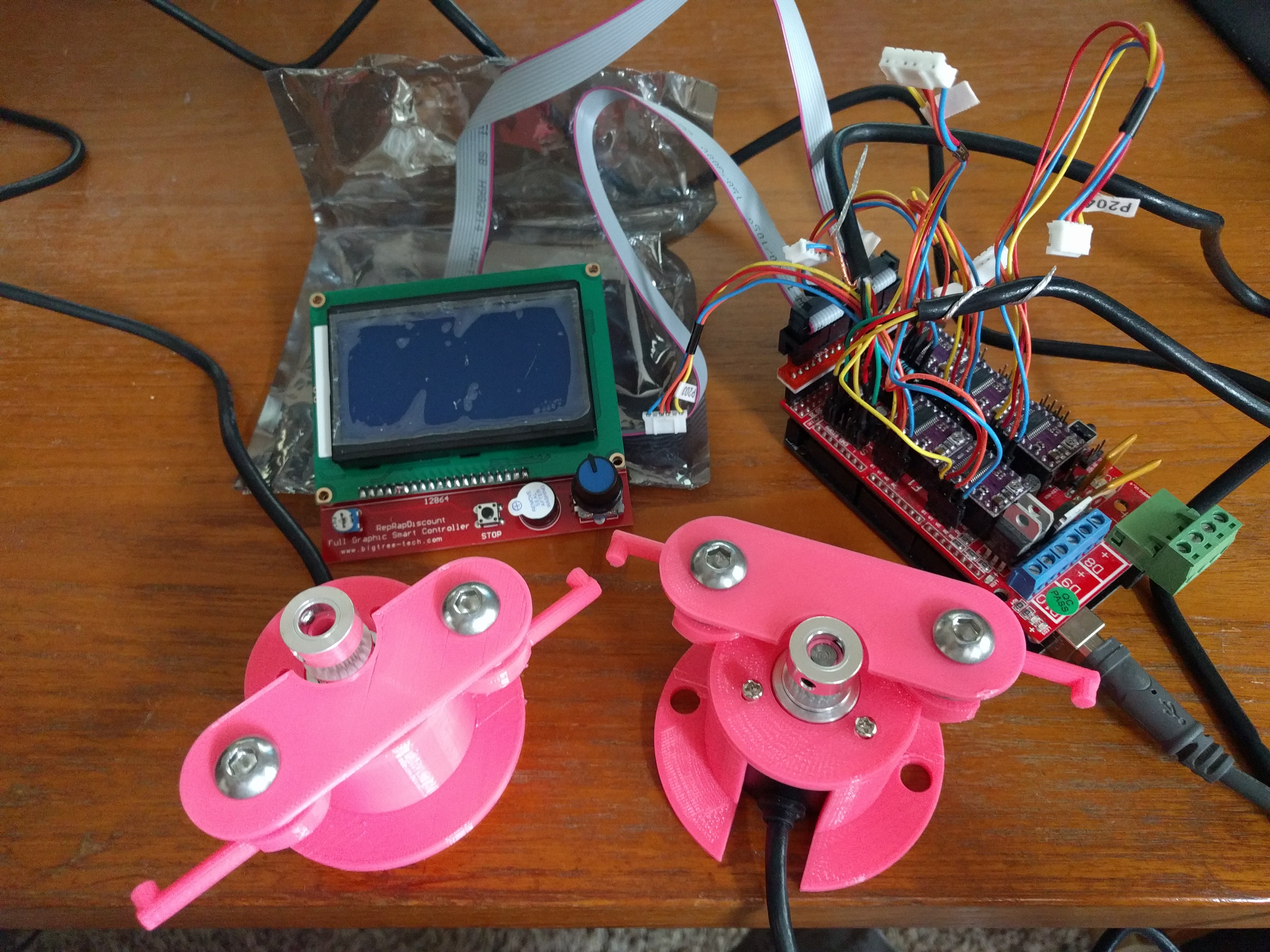
The steppers will be driven by an mega and ramps 1.4 board. The SD-Card will have the full depth map file (For every x,y position a number for Z height will be specified). The mega will place the Z depth based on the bit's current location and will move the two shaper style steppers to compensate for error. If you get closer to the outside edge of the limit it will begin to pull up the z-axis to make it out in time.
Lastly how does the mega know it's location? Easy picture a draw bot but a little backwards. The 5m (16ft) of GT2 belts are wound up around a 3D printed spool that is spring loaded. It then travels around the GT2 pulley attached to the encoder then out the 3D printed guides. This end is attached to a screw. There are two opposite facing ones in the bottom left and right corners.
HOW TO USE IT:
Place the depth map file on the SD card and insert into LCD smart controller. Screw the location tracking belts to the bottom left and right of work surface. Power on the mega and pull the Shaper to the center of the work surface. Power on the DeWalt drill (momentary power foot switch suggested). Use the LCD screen to start the cutting in the Z-axis direction and set the x,y position to 0,0. Based on your current position the router will move to the correct Z height. Just move it around until it drops into the cutting surface, try your best to follow where it is cutting. If you go out it will come up, move it around again until it drops back into the work surface. I would like for the screen to give you hinters of the next closest cut point. Cut till the job is completed.
Hopefully this all makes sense. I have a few things that are left to be figured out.
1. I suggested a 400 pulse encoder (for price $9 each) is that enough precision for a 16 tooth gt2 pulley?
2. Programming the mega to drive the LCD screen, get map from SD-card, control z-axis, and calculate coordinates
3. Auto adjust for x and y axis (v2)
4. Could the mega have trouble completing all these tasks?
5. Figure out how to convert a g-code file into a depth map file. (v3)
6. Compensate for rotation of the device.


Hi
Awesome project.
Have you tried these ideas :
- a computer vision solution using a mehtod similar to their encoded sticking paper ? (a nice feature would be to be able to attach your smartphone to the mobile CNC and use it as they do as an augmented reality / input device - even if I putting an expensive smartphone near a vibration source is a bit risky)
- using at least two optical mouse diodes to measure precise translation and rotation ? (even if as mentioned before it won't be a reliable solution on a dusted surface)
links :
o https://artoolkit.org/
o https://www.edn.com/design/sensors/4439292/Rotational--or-linear--measurement-using-an-optical-mouse-sensor
o https://sites.umiacs.umd.edu/elm/2016/03/09/mushaca-a-mouse-supporting-rotation/
o https://hackaday.com/2012/09/15/robotic-odometry-from-an-optical-mouse/