 Salvador Mendoza
-
1Step 1
The only necessary changes in the original MagSpoof design to work with this project:
-Remove the button and replaced it with a 10k resistor.
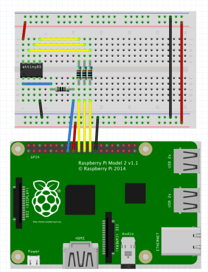
I will use Raspberry Pi pin numbers(board numbers), NOT GPIO numbers to describe this instructions.
We will need four 1k resistors, connecting the Raspberry pins:
-Raspberry pin 15 as reset button, to the Attiny’s PB5.
-Raspberry pin 19(MOSI) to PB0.
-Raspberry pin 21(MISO) to PB1.
-Raspberry pin 23(SCK) to PB2.Then connecting the Raspberry Pi GND(pin 25) to Attiny’ GND and Raspberry DC power 3.3(pin 17) to Attiny’s VCC. Example:
![]()
The pin 7 will help to control(on/off) the MagSpoof after a succeed installation of MagSpoofPI. So the end user will be able to enable/disable the MagSpoof without removing it from the Raspberry PI GPIO. So the pin 7 is connected to a 10K resistor. The another end of the resistor to GND.
Completed configuration example:
![]() After this, you can find the instructions to install the MagSpoofPI library in the github repository.
After this, you can find the instructions to install the MagSpoofPI library in the github repository.
MagSpoofPI
Be able to make & upload MagSpoof with variable tracks, to use it without Arduino dependencies, and implement it on the same Raspberry GPIO.
 After this, you can find the instructions to install the MagSpoofPI library in the github repository.
Discussions
Become a Hackaday.io Member
Create an account to leave a comment. Already have an account? Log In.
need help with a magspoof v3 email me 123caltempa@gmail.com $$$
Are you sure? yes | no