-
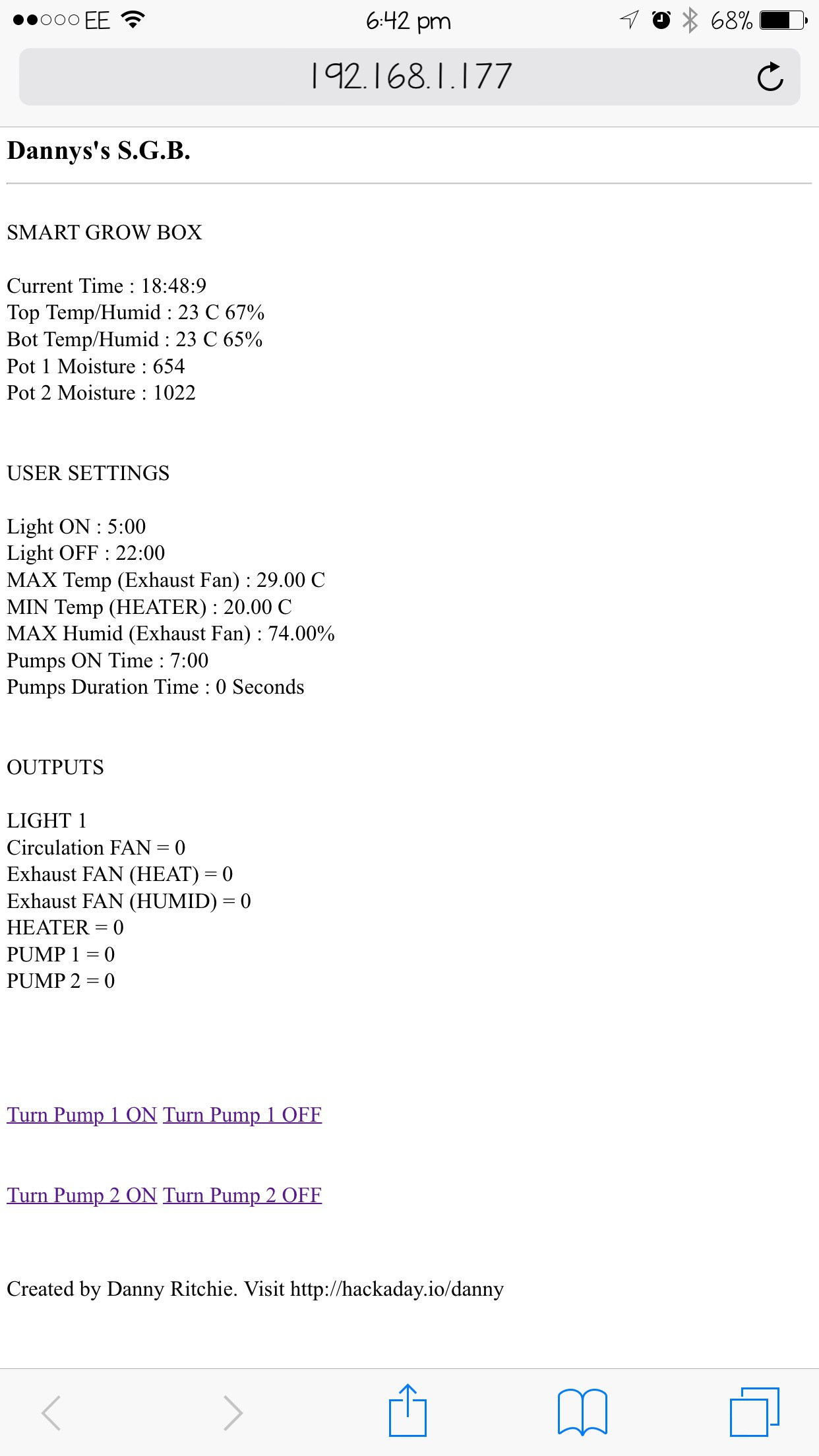
Added Ethernet and Webserver
01/25/2015 at 19:01 • 0 commentsWell inhale now decided not to use the gsm module from adafruit until I can understand it a bit more. I have however added an Ethernet shield which I have running a webserver which allows me to view all sensor information and what outputs are active. I've also started to add buttons for manual opperation of the pumps but don't quite have them fully working. I've also fixed a little annoying bug which was that I have humidity and temperature both control a single output and which ever one was written first in the code would cause the output to pulse. I've solved this buy having both humidity and temperature have there own output and connect a diode onto each one then join them to the external fan relay out.
-
Need some help with gsm support
01/19/2015 at 09:35 • 0 commentshi all I'm hoping someone reading this can help me. I recently bought a fona gsm module from ads fruit. I managed to get the fona to recurve a text message and display on my lcd of my smart grow box but i could not get it to do all of the time. I'm also struggling to figure out how I could send a text message to the unit and have it relay some information back to me. So if there is anybody out there that can shine some light onto this for me would be a great help.
-
Making progress.
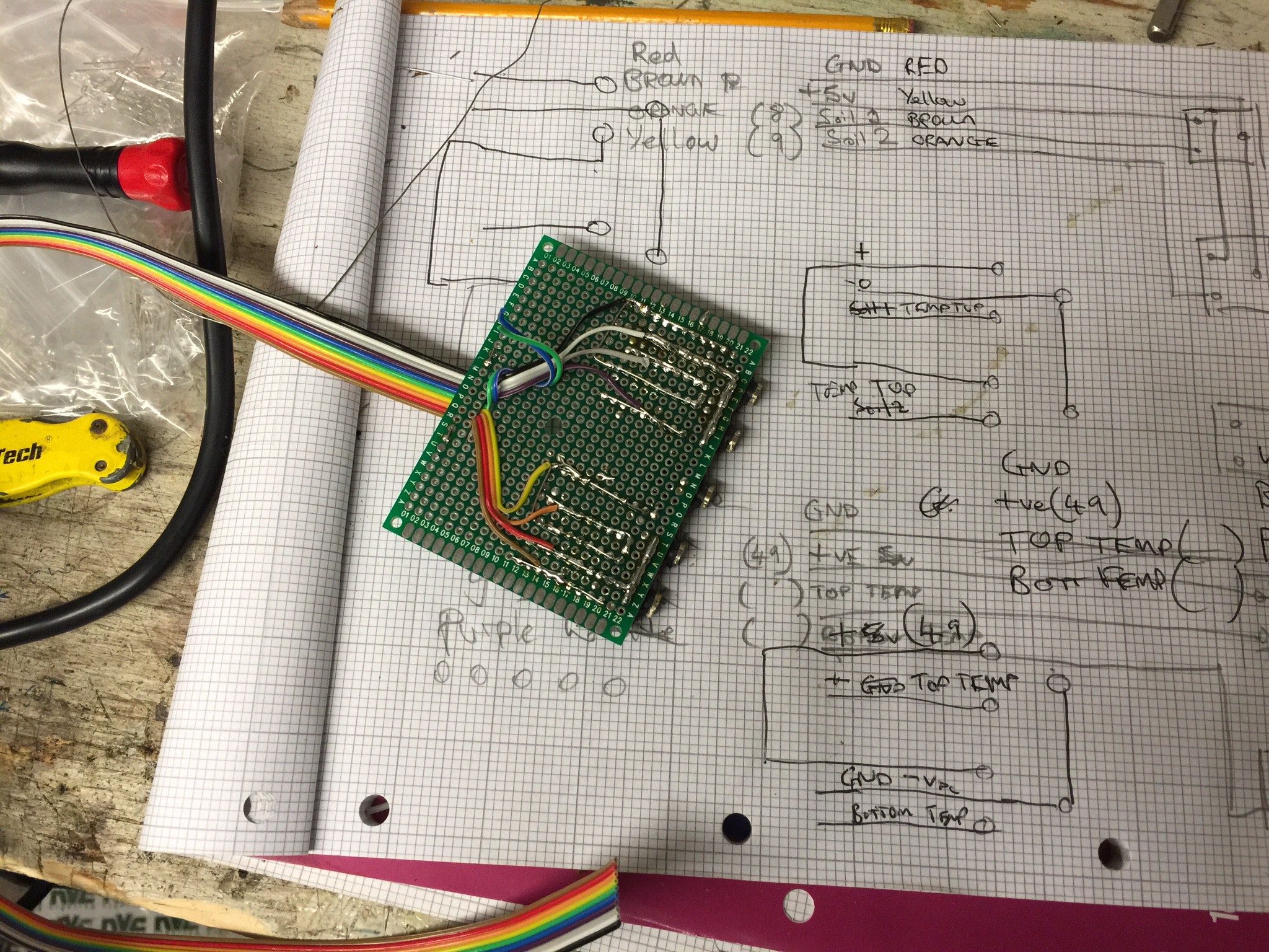
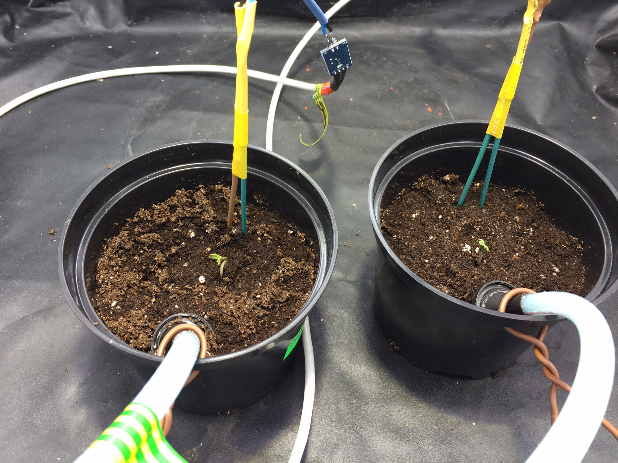
11/17/2014 at 18:35 • 0 commentsWell its been a while since i last updated my progress and as you can see I've had a lot of progress. I've finally got round to finding a suitable enclosure to house everything, Im just waiting for some 3 pin plug sockets. I now have my soil sensors with custom probes installed and working so rather than just watering the plants daily they will only get watered when needed. The soil gets checked every hour and if soil is above a set level then will activate the water pumps for user set duration (can be set from front panel :) ). All fans and light are now running off 230v and controlled via individual 40A solid state relays. I am in the process for adding a heater as I've noticed the temperature dropping an the night.
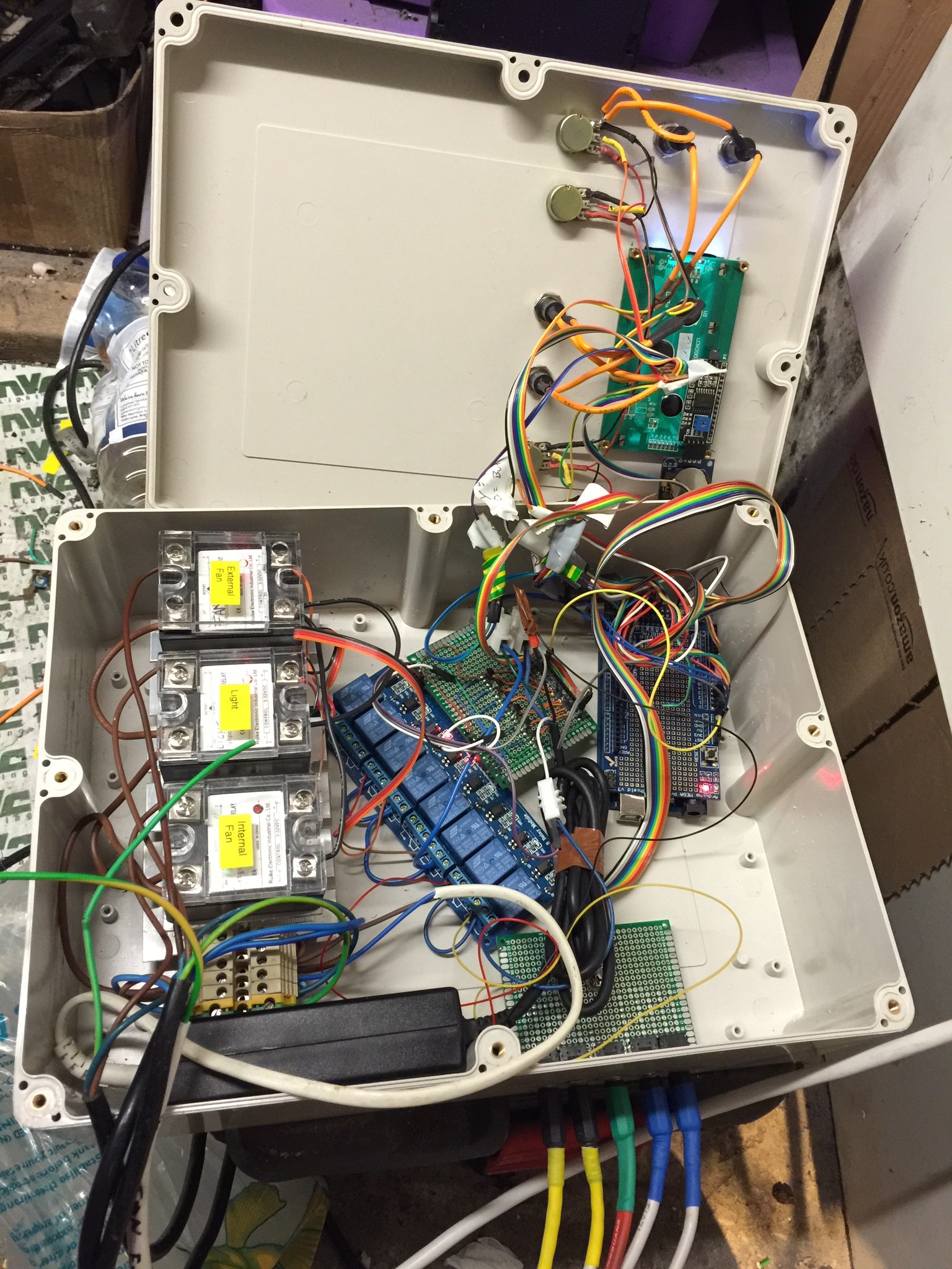
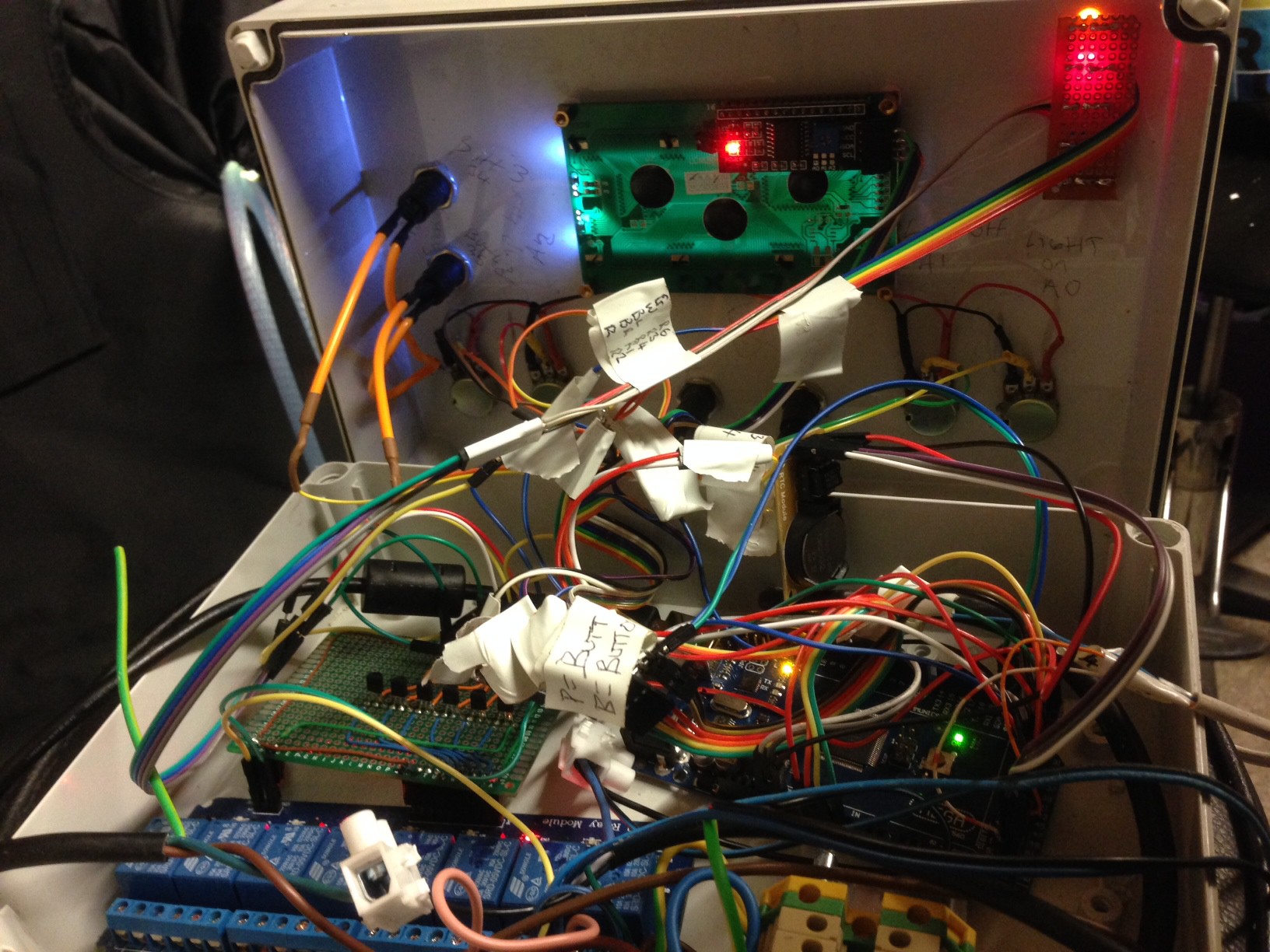
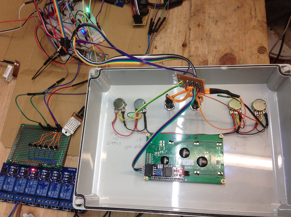
Heres a pic of the insides a little bit messy, at the bottom right of the box i have installed 5x 3.5mm stereo jacks and made the two Yellow jacks for temperature sensors, Green is for water pumps, and Blue for the soil sensors.
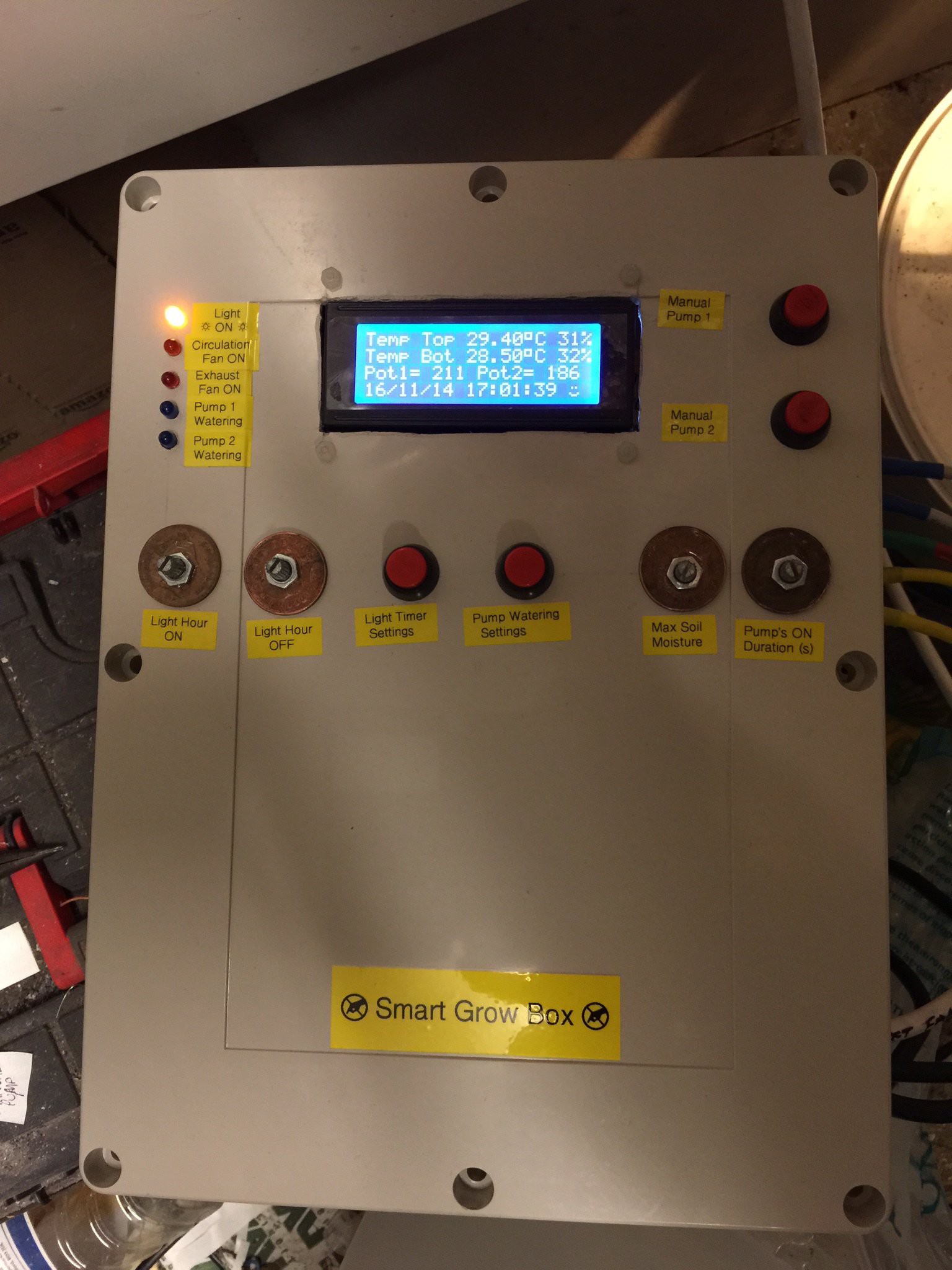
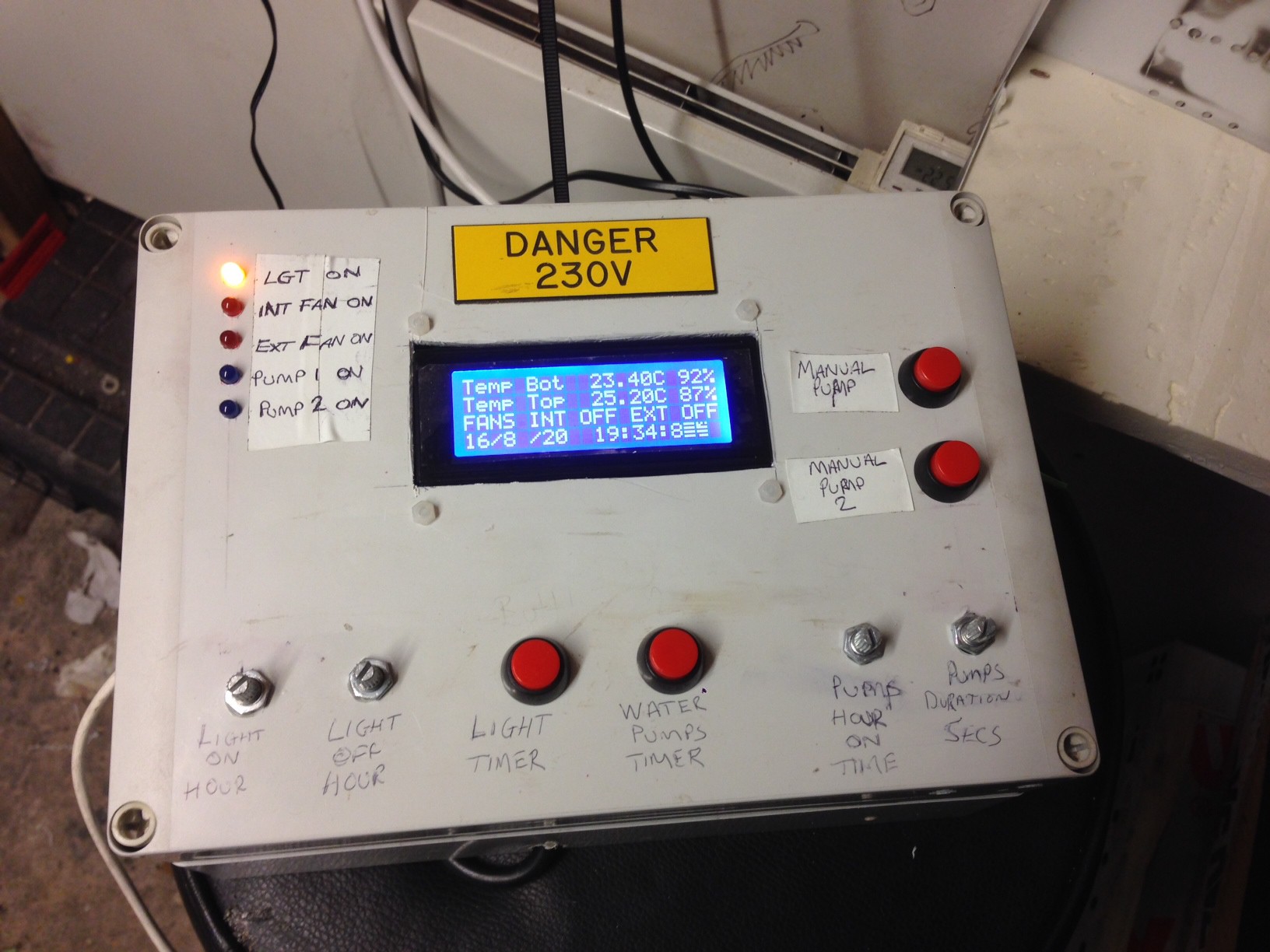
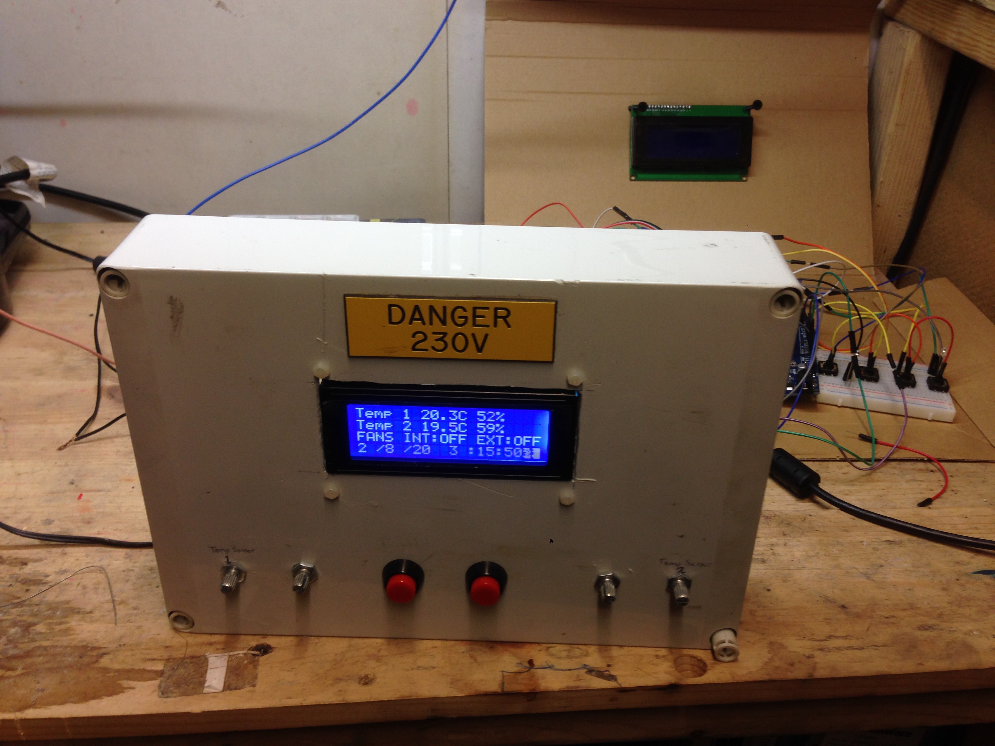
Heres the main control panel from the front
3.5mm jacks just installed.
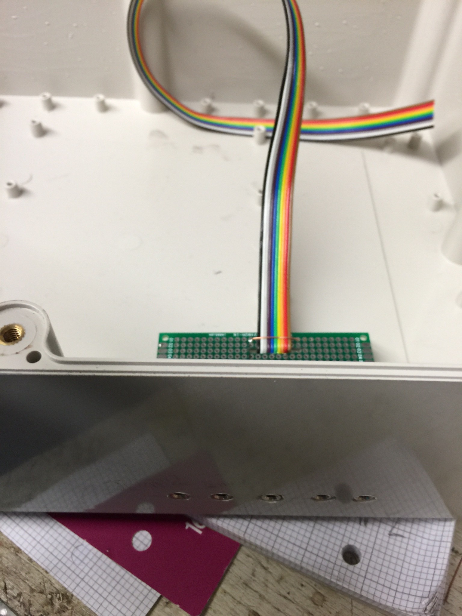
the 3.5mm jack panel, I originally only was using it for inputs then later added the centre jack for the water pumps.
A close up of the soil probes.
-
System now up and running.
08/16/2014 at 23:16 • 0 commentsFinally got around to sorting out an enclosure to house some plants and the system. The main lid has now got my indicator LED's and manual watering buttons installed. I've managed to fit it all in the box in a kind of fashion.
So far the system has been running for about a week and am happy with the stability managing to maintain around 23degrees C and 75%/80% humid.
Ive started to work on way to control through serial so i can control/view via a raspberry pi remotely. Im currently trying to figure how to configure the rtc without having to do a full upload,
Here's the main box with new status lights and manual water pumps.
Here's a pic of the inside of the main box.
Here's a pic of the setup i had running this week before adding the LED's and buttons.
-
We have Pumps, Lights and Fans
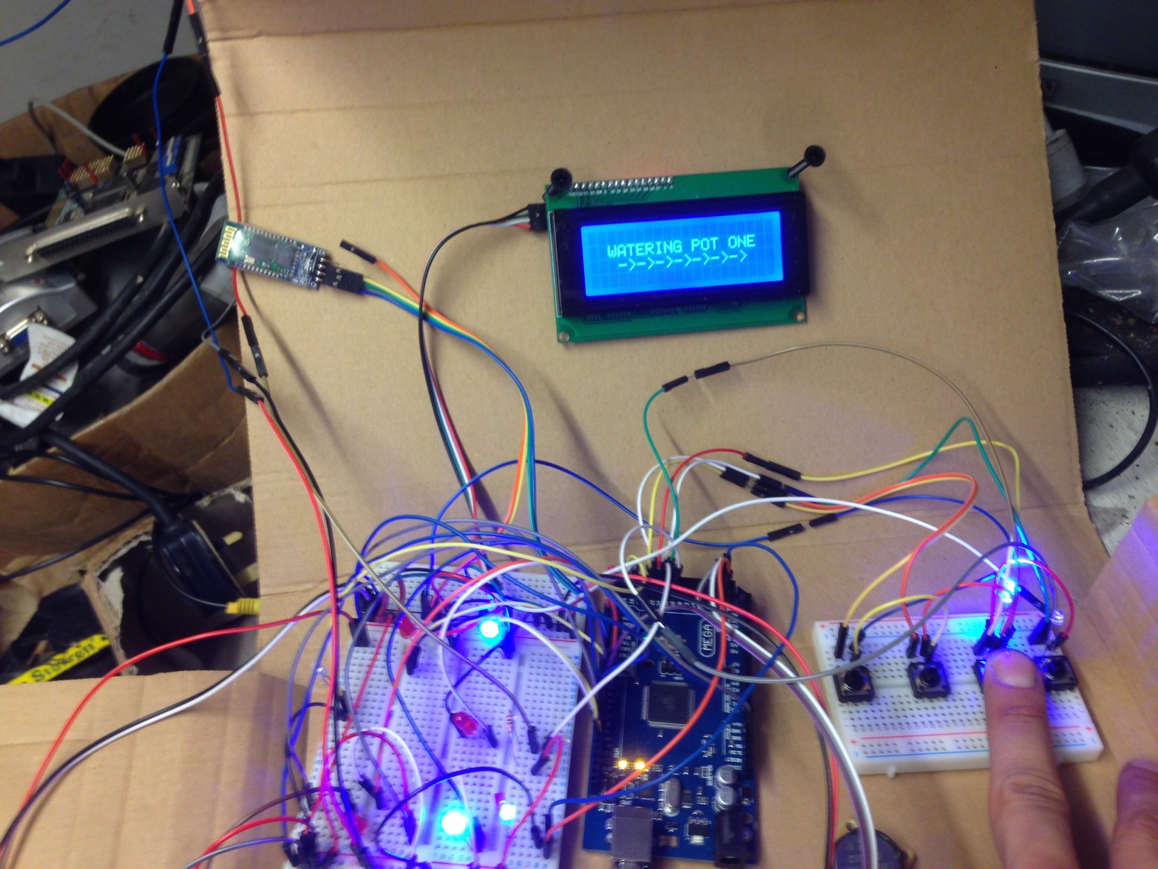
08/09/2014 at 12:23 • 0 commentsWell here is the current state of my project which to say the least i am very happy with how this is turning out. Since the last main project log in which i added an RTC and light timer I have now started to make an enclosure. I've started the front panel which at the moment consists of the main lcd, 2 push buttons and 4 potentiometers. If i hold the left button i can then see the light timer menu I can then adjust the left POT for on time and the right pot for off time. The second button brings up the watering pump timer, I select the on time with the left POT and duration is set with the right POT. I've set it up so pump one waters first then pump two will water one minute later.
Here is a vid of the pump timer in action.
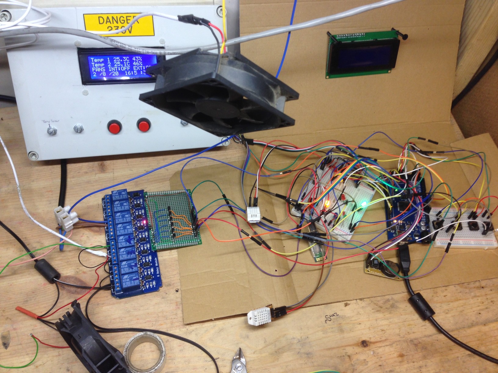
Heres a video of the Temperature controlled fans.
heres the code for the pump timer.
//PUMP TIMER
{ if
(((myRTC.minutes) == pump_on_hours)
(((float)myRTC.seconds) < pump_on_secs))
{
digitalWrite(pump1, HIGH);
lcd.clear();
lcd.setCursor(4,1);
lcd.print("TIMER");
lcd.setCursor(4,2);
lcd.print("WATERING POT ONE");
}
{
if
((myRTC.minutes == (pump_on_hours +1) )
(((float)myRTC.seconds) < (pump_on_secs -21)))
{
digitalWrite(pump2, HIGH);
lcd.clear();
lcd.setCursor(4,1);
lcd.print("TIMER");
lcd.setCursor(4,2);
lcd.print("WATERING POT TWO");
}
}
Close up of front panel,
Rear of front panel,
-
Just a little teaser
08/03/2014 at 17:35 • 0 comments -
Added a RTC with light control, a 4 button menu, and manual watering pumps.
07/12/2014 at 20:58 • 0 commentsI have been pretty busy on this project this weekend. Firstly i have decided to get rid of the soil hydrometers until i can use something that measures them more reliably as the probes I'm using are corroding very quickly which is changing the readings dramatically, and really don't want to flood the plants. The four button menu i have created is very simple as i have just assigned a 4 pins as pull-ups and to be a LOW INPUT. When either buttons 3 or 4 are pressed this runs, the pump will run until i release my finger.
//ACTIVATE PUMP 1
if (digitalRead(but3) == LOW)
{digitalWrite(pump1, HIGH);
lcd.clear();
lcd.setCursor(2,1);
lcd.print("WATERING POT ONE");
Serial.println("WATERING POT ONE");
Serial.println();}
else
{digitalWrite(pump1, LOW);}
Buttons 1 and 2 are going to be used for displaying the states of the sensors and outputs. We will see how this idea plans out.
Iv added a RTC (Real Time Clock) to control the lighting, I am using the virtuabotixRTC library to take care of this my light timer is taken care of with another if statement,
// LIGHT OUTPUT TIMER CONTROLL
if (((myRTC.hours) >= 8) && ((myRTC.hours) < 20))
{digitalWrite(light, HIGH);}
else
{digitalWrite(light, LOW);}
Its a very simple timer but it seems to work quite well.
Im thinking about using something similar to control the water pumps maybe on a daily or every odd day will play about with this when i get the system running with a plants.
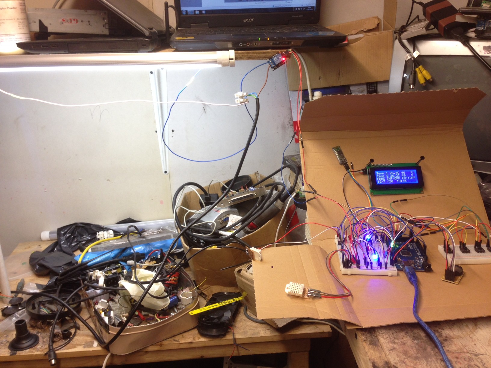
The pic below is the project in its current state controlling a light.
Here is a pic of the system manual watering, The blue LED above my finger is the OUTPUT.
Here is a demo video of the timer in action.
-
Bluetooth serial connection
07/06/2014 at 14:46 • 0 commentsWell today I've added a bluetooth module which i was planning on using in another project but wasn't quite what i needed. As you can see in the video below it works quite well and was easy to set up, just wire it up to pins 0, and 1 and the mega (Rx, Tx) pair with the laptop and select connection. In the future i would like to have maybe a Raspi connected so i can get, email alerts, maybe interact with outputs, and change sensor settings.
-
Nice bit of progress
06/29/2014 at 14:59 • 0 commentsFinally got back round to doing a bit work on this project,
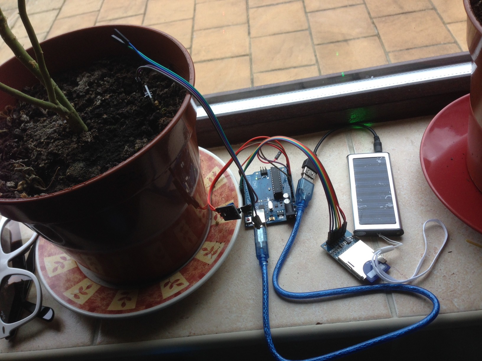
-Firstly got an arduino setup with sd card logging some numbers for my soil moisture sensors. hopefully should have enough data this week so i can finally add the watering pumps.
- Been working on the outputs for the fans made so good progress they seem to be ready for an actual test, when i get round to building an enclosure.
The next lot of pictures are the LED outputs for the temps. i have a RED, ORANGE, And BLUE for each temp sensor. RED = Too Hot, ORANGE = Perfect temp, BLUE = Too Cold
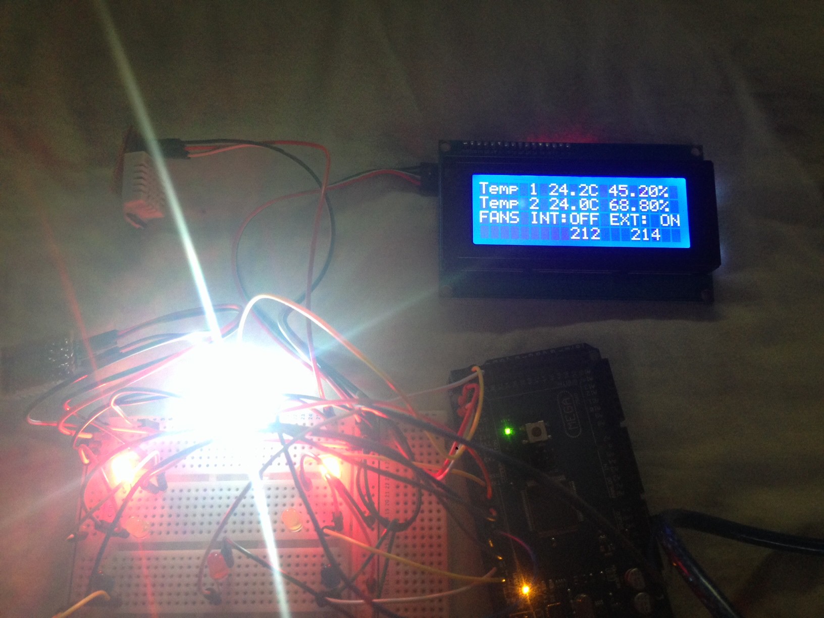
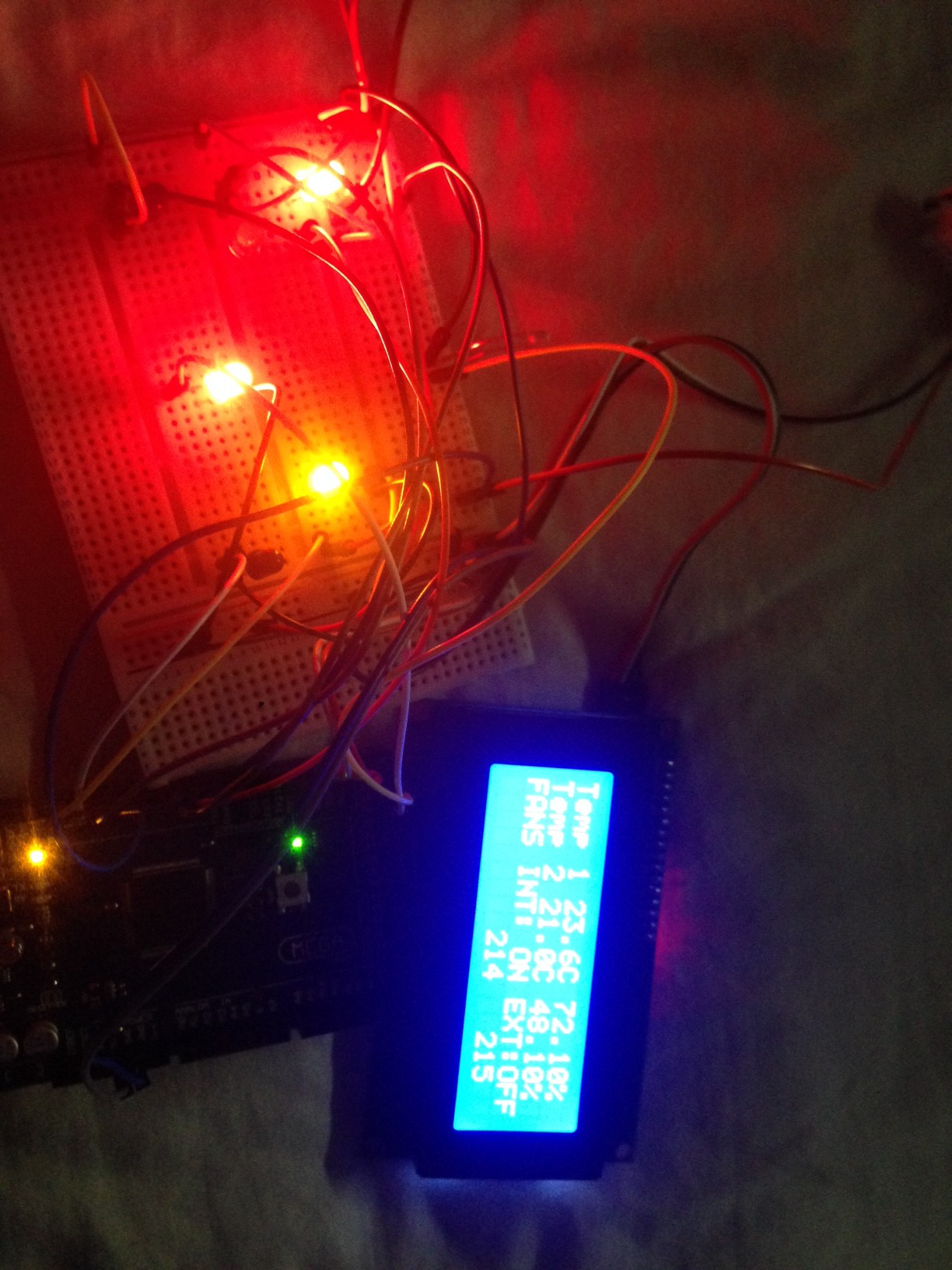
At the moment if one temp sensor is above 23C and the other is below 21C an internal fan will start (2nd RED LED) to bring both temps back in range. If both sensors go above 23C an external fan (WHITE LED) will start until both temps are back in range.
Ive also tidied up whats on the display so it will output the fan states.
Here the temps are within the set range so no fans on
Here both temps are above 23C so the external fan output is on.
Here the temps are different so the internal fan is on.
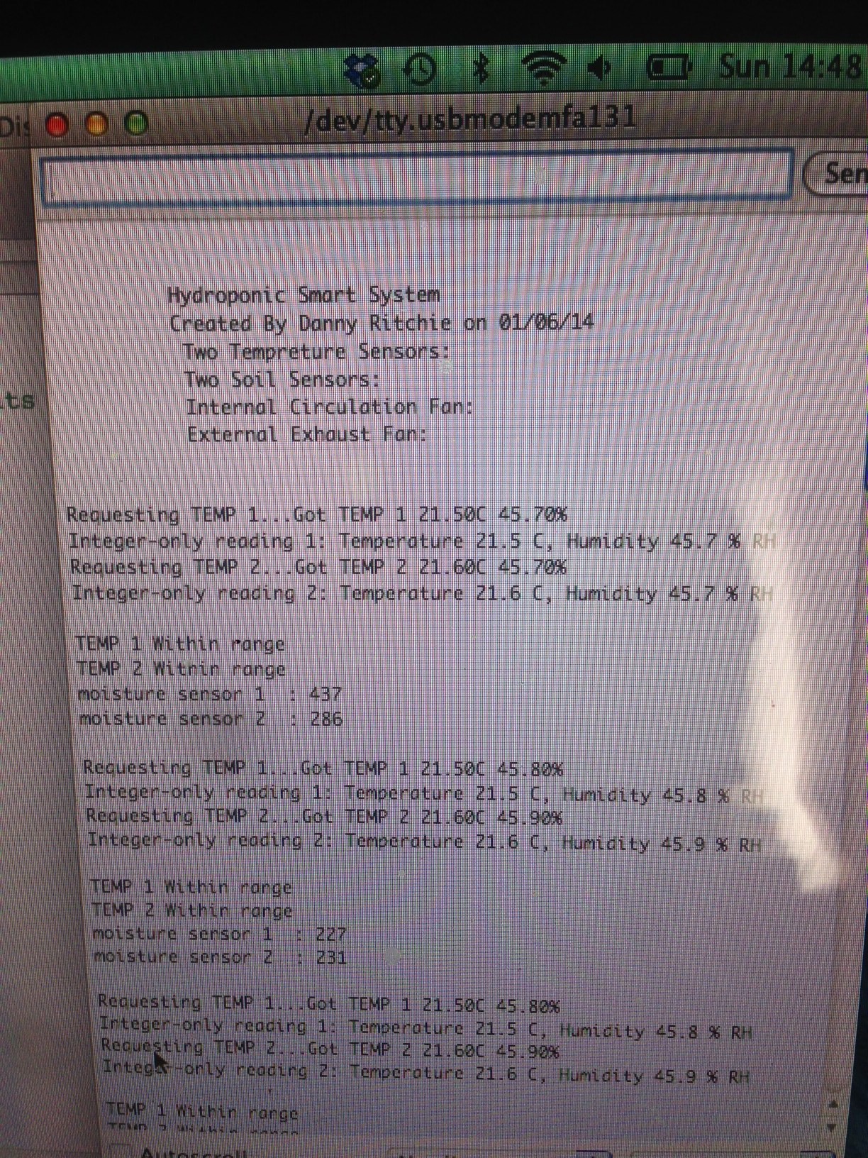
Heres my serial out put.
Smart Grow Room
Smart grow room. Fully automatic, Watering, lighting, temperature control. Self adjusting light height and remote control
 dannyritchie