Okay, so I screwed up. I was attempting to measure the power consumption of the Mini by putting a power resistor inline with the power supply and computing the power from the voltage across the resistor. That was the idea, but I was lazy and used clip leads to tap into the power at the barrel connector of the Mini, and I shorted the power supply by accident and it died. I should have opened the printer and tapped into the power wiring inside, but I was in a hurry because I wanted to get back to a big printing project and in my haste I killed the power supply. Thankfully, the Mini itself was fine when I tested with a benchtop supply. I only killed the power supply.
The idea of using a bench supply every time I used my mini was bugging me, and I had seen other people replacing the supply and relocating it inside the Mini before, so I decided I would try to make an internal supply mod for my Mini as well.

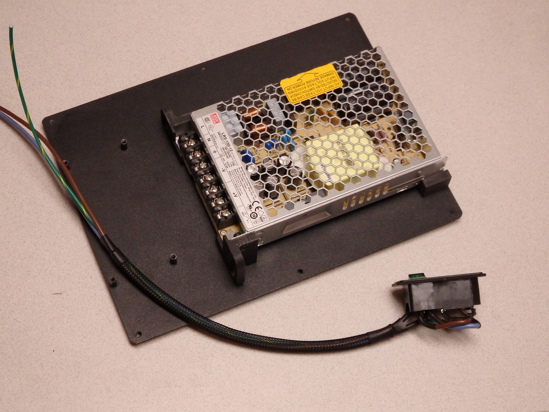
I hit the interwebs and tried to find a power supply that was small enough to fit inside the Mini, but had better specs than the stock supply. I wanted something with more current, so I could further mod the Mini and not run into power supply loading issues. The stock power supply is supposed to provide 10A of power at 12VDC, so the stock supply should be rated for 120 Watts (10A * 12V = 120W). By picking a higher capacity supply I would also be running it below spec and it should stay cooler as well. I settled on using a Meanwell LRS-150-12 supply. These are 150W at 12VDC, and sell for about $20 online, and my measurements indicated it would fit inside the Mini case.
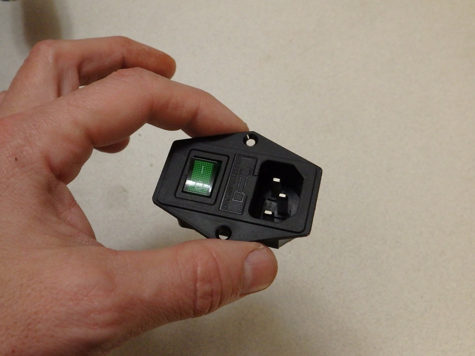
While I was messing around with the power supply, I decided I would add a switch and a fuse and when I was looking around I came across a nice little IEC320 C14 Power Socket with Illuminated Switch Fuse Holder on Amazon (Search for the part by name and several sellers come up). I did some measurements, and determined that the socket would fit in a hole that completely covered the existing power input and switch holes in the Mini, so it would look like it was a factory installed component.

When I got the power supply I test fit it inside, and there was plenty of room. However, the supply covered the vents in the bottom of the case. The height of the supply is short enough that I decided to raise it up on metal threaded standoffs so that it would have ventilation under the supply. The problem with this idea is that there are only two mounting screw holes on the bottom of the supply. The holes are on opposite corners, so they could hold it in place, but it seemed a little unstable for my tastes. I ditched the standoffs in favor of some printed mounting brackets that would hold it in more than two points.

While my mounting brackets were printing, I wired up the input wiring. Based on the test fitting of the power supply, I opted to directly solder the power wiring to the lugs on the power socket and switch, instead of using crimp on spade terminals. This allowed me to better insulate the wiring with heat shrink, and bend the lugs over to provide extra clearance behind the power supply. This is how the power is wired for use with US 120VAC power.

My printed mounting brackets hold the supply on the bottom edge and side edges and provide attachment on all four corners, I also added some wire harness guide loops to assist in routing the wiring inside the Mini. I tweaked the size of the brackets for maximum clearance for the cooling air to come in through the vent holes below the power supply, and split the one bracket into two sections so there would be an air passage to flow from the vent to the CPU board. You can download these bracket files from our Thingiverse page at the following link: http://www.thingiverse.com/thing:1881464 (see that page for printing instructions)

When installed, they held the power supply firmly in place and had plenty of air gap over the vents to allow cooling air flow under the supply. I turned out great. The edge of the supply with the screw terminals just fits under the Z stepper motor, so I had to be careful where I located the supply mounting. In the end I found a location I was happy with.

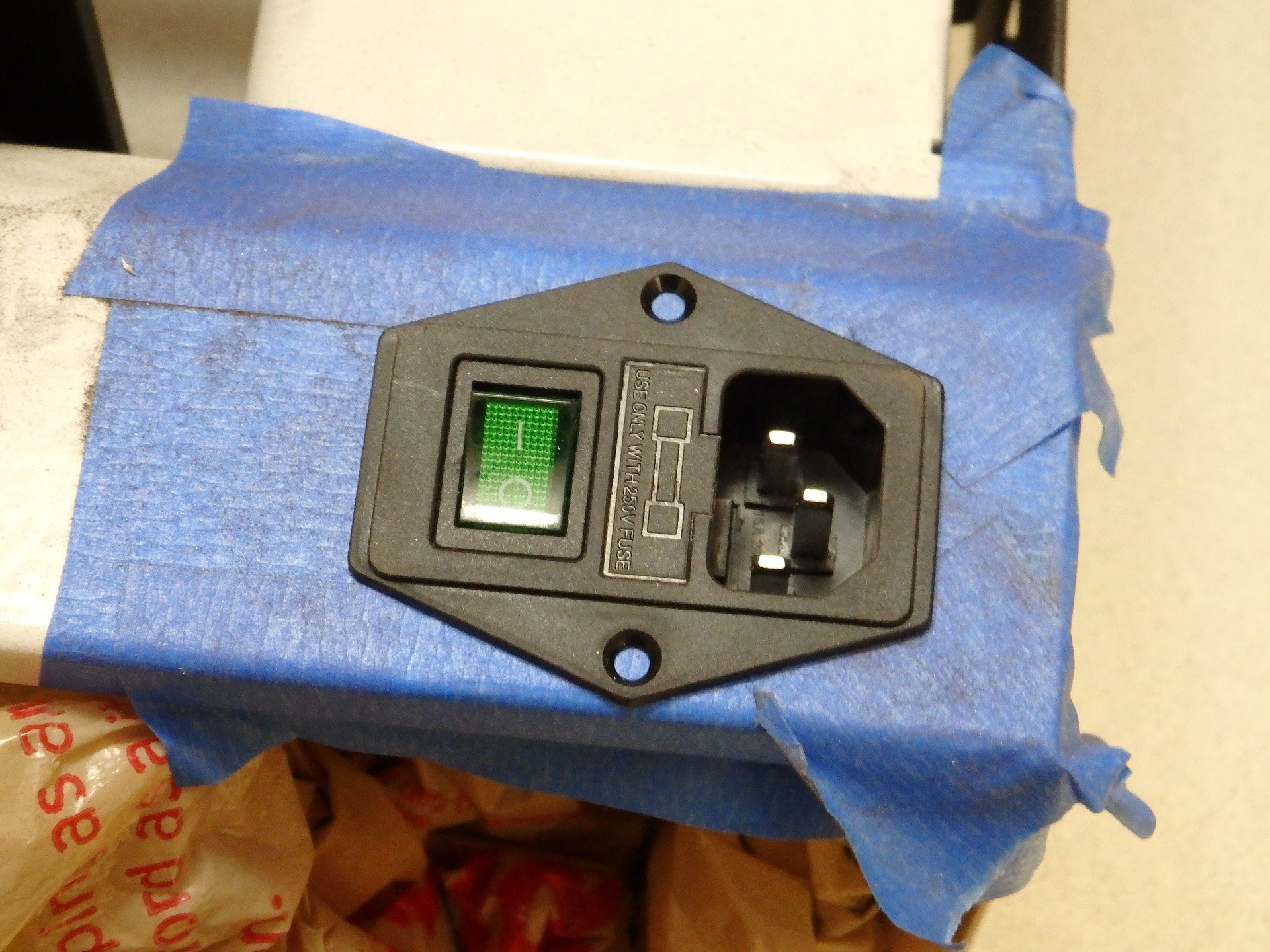
Cutting a hole for the Power Socket was simple. I just used a Dremel tool with a cutting wheel. The steel was a lot thicker than I thought it would be, but working slowly and putting tape over the areas I wanted to keep pristine helped. I also stuffed plastic bags inside the Mini case, to prevent the dust and shavings from getting on the mechanism or electronics.

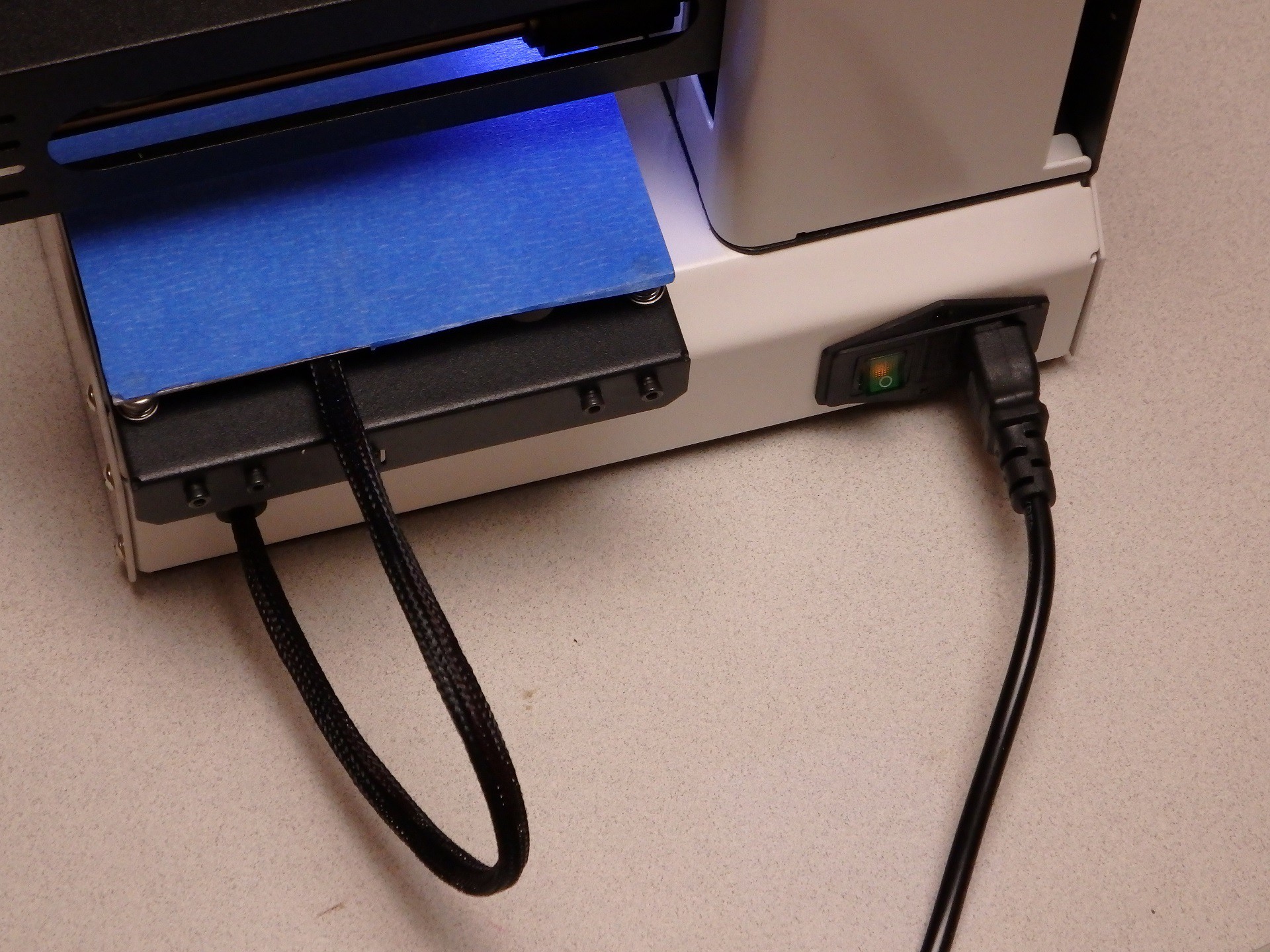
The sharp edges were cleaned up manually with a file and smoothed to the point I was happy they looked decent, then I test fit the Power Socket. The final bit of this work was finished up by drilling the mounting screw holes. I used some M3 flathead screws and nuts in the bracket to hold it in place.

When everything was buttoned up, the only thing I needed was a fuse for the Power Connector (It didn't come with one). I have seen where many people had the same issue with this connector and they ran out and ordered a fuse to match the current rating of their supply, but this is wrong and dangerous. A 10A 12V supply does not require a 10A fuse on the AC input side of the supply. You would use a 10A fuse if you were fusing the 12V lines. In the case of our Power Connector, the fuse is wired to the AC input, which has a significantly higher voltage, therefore the current needed is lower. I couldn't find the complete specs for the power supply, so I measured the AC current draw of the Mini with both heaters running and measured 2.6A on the AC input. I put a 3A fuse in the socket and it didn't blow. The inrush current of the power supply caused by turning the switch on and off didn't blow it either, so I think I have a good value for the fuse.

I'm really pleased with the way it turned out. I just completed a 56 hour long print with the Mini, and it worked flawlessly. I really like this mod. It did kind of blow up my budget on this project because it ended up costing about $25, but I think it looks really nice, and of course it frees up space on the desk by eliminating the bulky external supply. The added safety of the fuse is also a bonus. let me know what you think of this mod in the comments section. Enjoy!
Stay tuned for more mods!
 U.S. Water Rockets
Discussions
Become a Hackaday.io Member
Create an account to leave a comment. Already have an account? Log In.
I'm thinking of using this with a silicone pad for heating, bed insulation and going 24v
Are you sure? yes | no
im currently doing this upgrde cause I'm putting in a Maximus extended bed kit in and the heater that goes with it. Do the printed mounts fit a 200w 12v Meanwell PS as well? Also did you have to drill the holes to mount the PS to the inside bottom of the mini? Thanks
Are you sure? yes | no
Hi did you ever test or find out if the printed mounts fit the a 200w 12v Meanwell PS?
Are you sure? yes | no
no I didn't test or find out if it worked with it or not. Never got a response.
Are you sure? yes | no
Hello, I am working on this mod right now for my printer. I put in everything and wired up the power supply only so I could dial in the volatage before attaching the printer to the new power source. As soon as I flipped the switch on the outlet and immediately blew the fuse in the IEC320 C14 Power Socket with Illuminated Switch Fuse Holder I picked up. It was only 5A and I also realized I left the transfer on 230VAC and not 120VAC. What size fuse are you using? I want to make sure I have a large enough AC fuse when I get replacement fuses.
Are you sure? yes | no
With the extra amperage from the new power supply, can you get the heat bed up to 110C? There's another project on here involving adding a second power supply and a slave heater, but that seems far too complicated if just swapping the power supply could increase the bed temperature.
Are you sure? yes | no
Add this guy to your arsenal:
https://www.amazon.com/dp/B00O1Q2HOQ
Are you sure? yes | no