 danjovic
The ATTiny85 internal RC oscillator drifts so badly that it was not possible to have a good image.
It was tested on two TV sets with similar result.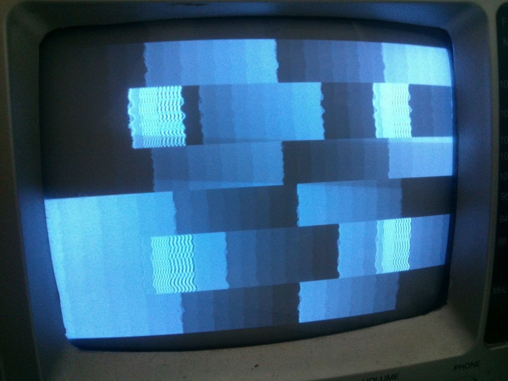
The circuit have been powered by both an arduino actig as a power supply and a battery (to eliminate any chance of power lane induced instability).
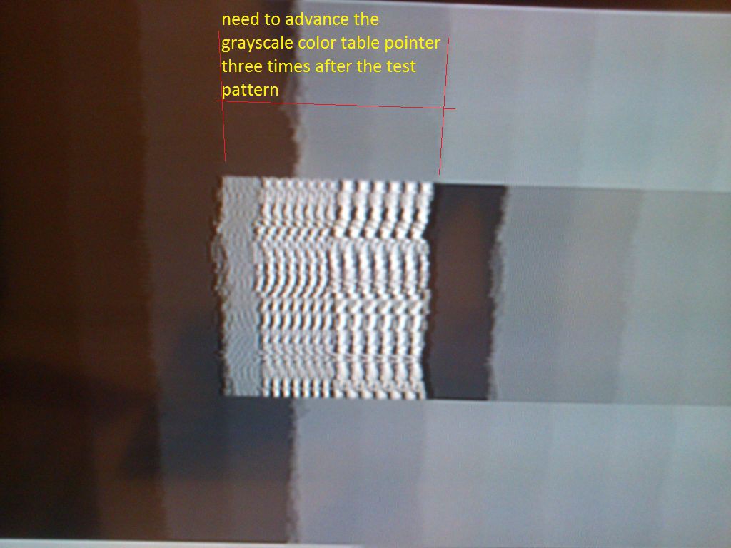
The code needs to be corrected (by advancing a pointer) to compensate for 3 missing shades of grey during resolution test pattern.
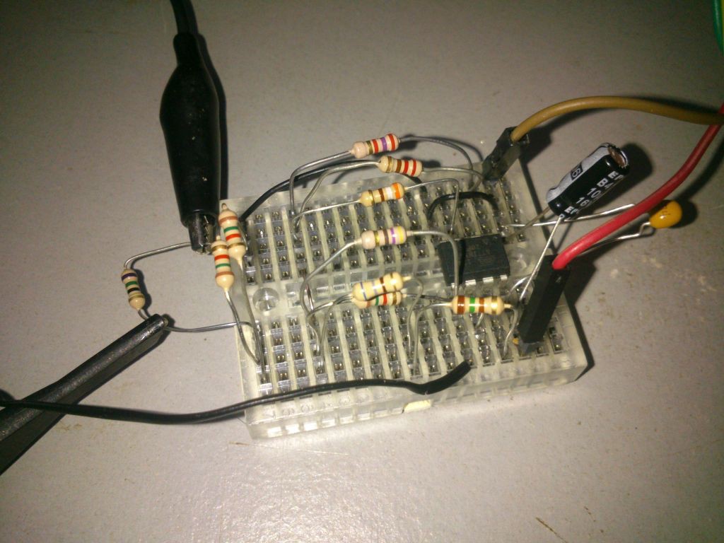
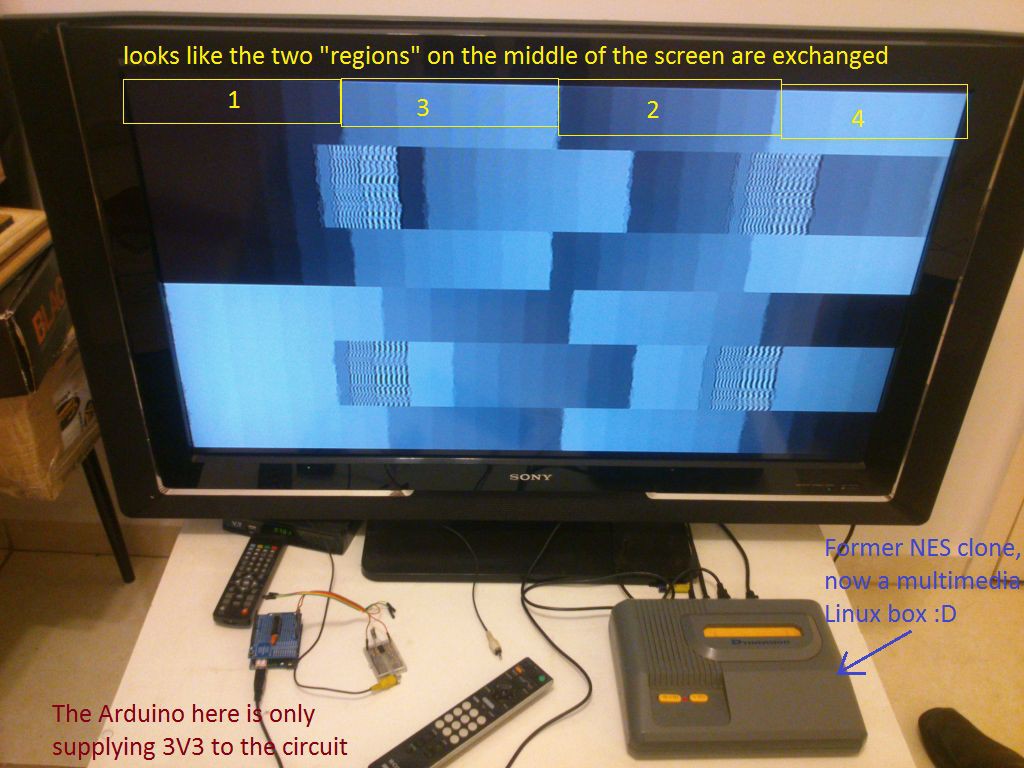
It looks like some of the resistors are corrected to the wrong pins as the grayscale is not progressive but rather it looks to have 4 distinct progressive patterns on the screen following the order 1 3 2 4 instead of 1 2 3 4.
Discussions
Become a Hackaday.io Member
Create an account to leave a comment. Already have an account? Log In.
Wow, that oscillator really is unstable (hardly your fault). I've tried VGA using an internal oscillator on one of the MachXO2 FPGAs, and it wasn't that bad - they may be using a ring oscillator instead of an RC, though.
Can you do with fewer resistors in the DAC?
Are you sure? yes | no
Hi Ted... Yes, I am considering the use of an external clock generator and reduce the amount of grayshades to 16... For now I am polishing the code using an Arduino board and will very likely use an ATMegaxx8 on the final version of the circuit (which will also allow me to reach the 50 shades and turn the project name in a perfect parody of the book :D )
Are you sure? yes | no