Lee Cook
-
Another post, another poser attempt
03/29/2018 at 11:20 • 0 commentsIt’s been a long while since I worked on this project, life got in the way and, to be frank I think I burnt myself out of enthusiasm trying to get the circle:ellipse approach I outlined in my last post to work. The actual ellipse fitting algorithm worked like a charm, however, the type and amount of distortion perspective would put in to the “ellipse” ended up being way more than I was able to efficiently to compensate for. Essentially, the circle is transformed by a parallelogram which, unfortunately, moves the original centre line to above/below the point of maximum width:
![]()
Trying to understand this effect lead me to a paper by Randall Bartlett a professor at Auburn University. In the paper (The Bad Ellipse: Circles in Perspective), he confirmed that the minor axis does align with tilt direction of the plane the circle is on vs the viewing point, however he explained it in terms of vanishing points (giving rise to the parallelogram). It was at this point I ran out of steam and let home and work life take over for a long while.
Over the past few months there has been a renewed vigour on the @CNLohr LibSurvive project with the Discord chat becoming very active and, while I’m not contributing to Libsurvive, it did actually give me the impetus to try another time to get a working poser for my system. So, after quite a bit of reading on ellipses, vanishing points and other related topics, it finally dawned on me that I should be able to use the vanishing point principle to make a poser.
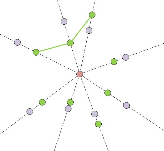
The approach is fairly simple, if the base station is moved from its current position in a direct line toward the centre of the sensor cluster then the sensors would appear to move in a straight line toward/away from the centre point of the object. I.e. they would move toward/away from the vanishing point (think of the stars in a Star Trek warp journey):
![]()
So, if you take an estimate of the bearing with an arbitrary range (red point) giving theoretical points for the sensors (purple), you can then work out what the estimated angles between the sensors are. These angles would remain constant regardless of the distance the base was from the cluster. There is then an iterative process where you take groups of three sensors and, using actual sensor position data along with the angles from the bearing estimate, you find the point which would gives that pair of angles.
Doing this for all the visible sensors will give a number of positions, you then iterate and refine the estimated bearing until the positions converge and the angles match the estimate at the convergence point. So, once you have the bearing, you then alter the range until the angular distances between the points and the bearing point are the same. You can also look at the rotational aspect by looking at the measured angles vs the cluster relative axis.
After all this, you should have a range, bearing and base rotation wrt to the cluster on that bearing.
-
About turn again - The Mathematics
01/18/2017 at 12:30 • 0 commentsAfter taking a detour (and dragging a couple of others with me) through the realms of ePnP, I’ve done an about turn and gone back to my original idea of using circles and their apparent ellipses for tracking position and attitude. I’ve already implemented most of the steps and I’m reasonably confident that this approach will work, though I still need to see how well it will sit on a 300MHz Cortex M7. Anyway, here’s the approach as it stands at the moment:
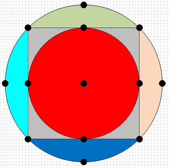
Take three sensor points in 3D space which have been lit with laser light (i.e. base angles are known). Construct a circle in 3D space using those three points and determine: the centre of the circle, the radius of the circle, the relative angles of the sensors around the circle and, the normal to the plane the circle sits on (use a combination of the three sensor normals to determine the outward facing side).
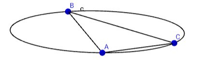
At the end of the process you should have something like this which shows a circle constructed from A, B and C:
![]()
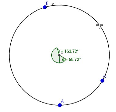
Once the 3D circle information is known then start working on the information from the laser sweeps. Use the relative angle/bearings between the sensors to determine the angular magnitude between the sensors (AB, AC and BC). These distances relate to a series of chord lengths around an ellipse with the defined theta angles between them:
![]()
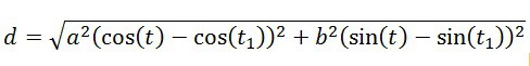
The following equation can be used to determine the length of a chord on an ellipse:
![]()
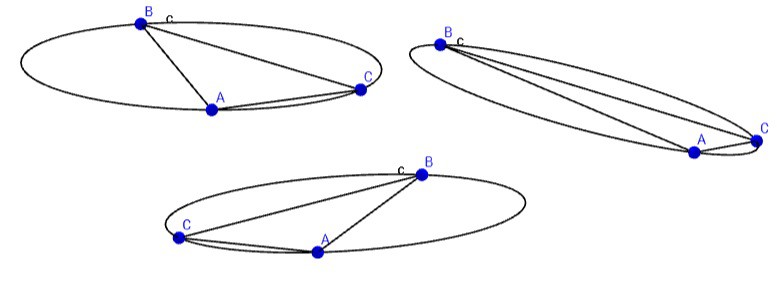
The problem easier due to the fact that, at this stage, there is only the need to match the ratio of the chord lengths with the ratio of the major/minor axis at those angles. This allows the removal of the minor axis as an unknown as well as the root. However, the problem is made more difficult in that the sensor group may be at any theta angle on the ellipse depending on the attitude of the HMD with respect to the base. This has the effect of “sliding” the sensor points around the ellipse as shown below:
![]()
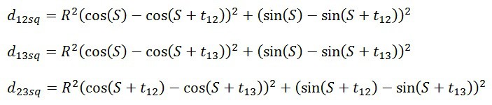
This basically boils down to a system of three equations where only R (axis ratio) and S (slide angle) are unknown:
![]()
Unfortunately my mathematical skills failed me at this point and I have had to solve this part through iteration. I’m still hopeful that a colleague will take a look at it and come through with a less computationally intensive solution.
Perspective errors in the ellipse can be reduced by taking advantage of the fact that there are actually two “slide” angles in the ellipse which will fit the chords - exactly PI radians apart. Solve for the slide angle in 0<S<PI and also in the PI<S<2PI ranges then average the two sets of results (still to do in the code).
Once solved, this gives a major/minor axis ratio, chord lengths (with the minor axis set to one) and, the “slide” angle at which the chain of chords starts, and we start relating the two sets of figures, circle and ellipse together to figure out the pose:
- The ratio of the major/minor axis gives the angle the circle has been tilted from perpendicular to the base.
- The “slide” angle will determine how much the HMD has been rotated around the centre of the circle (in the plane of the circle), use an accelerometer to determine up and the correct angle
- The ratio of the original chord length vs the calculated one gives actual length of the minor axis
- Scale the minor axis up by the major/minor axis ratio to get the major axis length
- Use the major/minor axis to determine the positions of the points wrt to a zero and then work back to determine the centre of the measured ellipse from the scan.
- The centre of the ellipse is a bearing to the centre of the circle.
- The major axis is the angle created by the circle radius length – use both to determine the distance between the base origin and the centre point of the circle.
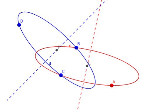
This is about as far as I have come so far. Through with use of external sensors and the sensor normals it should be possible determine the position and orientation of a base wrt to the HMD. Depending on how much this approach loads the processor I would also like to run this a few times on a few different sensors to reduce errors in the extremes of major/minor axis ratios (<1.5 and >4) where there are more uniform chord length ratios present. It would also allow the attitude to be better fixed by also locking vectors of other circles:
![]()
-
First iteration of a simulator
10/30/2016 at 23:15 • 1 commentIf there's one thing I've learned over the years it's that you need a decent simulator of the real-world characteristics of your system to develop & debug the control aspects. I've attached a zipped Java Netbeans IDE (8.2) project as the start of mine which will hopefully help with the developement of the maths algorithms...
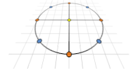
It's the first iteration which at the moment defines a spherical sensor cluster:
![]()
Imagine a six sided die blown up to a sphere. At the centre of what was each face, the middle of each edge and the 3-point corners is a sensor.
The cluster can be placed in a XYZ space, be given an attitude vs down (the output from an accelerometer) and then rotated on the horizontal plane for a heading.
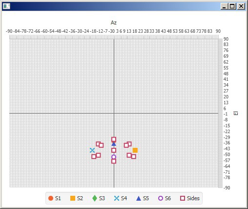
The program then prints an Az and El angle which would be read from a system similar to Lighthouse and taking the differences would be the output from my system:
![]()
The next iteration, hopefully done by the end of next weekend will fix the inevitable bugs. I'll also expand the functionality to look at the normals of the sensors vs the angle of the base along (potentially taking in to account distance too) to try and estimate if the sensor would detect the laser and, if it does, the duration of the pulse. I'll refine the estimates with real-world data as the hardware comes along.
-
The maths?
10/19/2016 at 23:50 • 6 commentsI’ve just put my thoughts down elsewhere while trying to explain what I see the maths problem behind this project, and I thought I’d share them here too. It’s quite late at the end of my third 15hr work day so a little slack is appreciated. That said, if what I’m proposing is a complete load of bo**cks feel free to point out the errors – with corrections please! ;-)
My system can't produce exact bearings/'pixels' like the lighthouse system does, but it can measure the relative angles between the various points and, in theory, relate those angles to an absolute distance.
It's similar, or perhaps even the same(?), as the n-point problem I think.
There is only one orientation (and from a perspective point of view, distance) of the target with respect to the laser emitter, which when scanned with the laser line, will give that particular ratio of angles. The problem arises because that orientation could be anywhere on the sweep of the laser, like a toroid in the axis of rotation. However, if you know the attitude of the target with respect to the axis attitude of the laser sweep, it becomes fixed against that axis – there is only one orientation of the target wrt to the laser axis which has that particular target pitch and roll.
The "orientation" reduces down to a relative translation of the target (x,y,z) with a rotation in target yaw/heading - and the whole thing potentially rotated around the vertical axis.
Having a second set results from another characterised laser scanner (characterisation done during the room calibration routine) and it should be possible to calculate the yaw/heading component of the target and fix the target on the XY plane.
The whole reduction thing relies on having known attitudes for the emitters and the targets so they can all relate in the same axis.
Anyway, that's my theory. I've talked to one of the mathematicians at work and he seems interested enough in the system to want to give me a hand getting it working. Perhaps when I give him this talk he'll laugh in my face at my naivety and point out I need 30 scanners to make up for the lack of real bearings.
I hope not.
-
Shelved no longer!
10/07/2016 at 19:08 • 0 commentsOk, I have come to the conclusion that in order for this to become a non-virtual reality (sorry, couldn't resist) I would need to progress it to the point where it generates interest. So.. I’ve shelved other projects and this will now take all of whatever time is left after work, a horrendous commute and family of four kids. (i.e. don't expect rapid results!)
I’ve ordered a load of line lasers, MEMS units and other bits which will be coming to me on a slow boat from China.
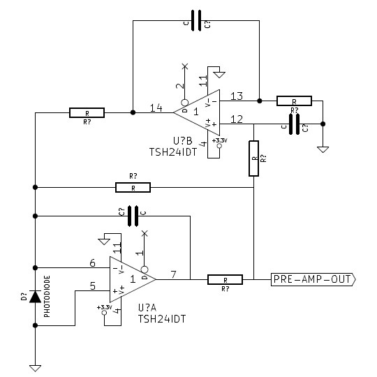
While I’m waiting for those I've been looking at photodiode detector circuits. The parts for this circuit:
![]()
(originally from <here> and copied later <here>) are on order as it looks the most promising starting point for the input stage initial design. Hopefully it will bias out a lot of the ambient light current but let the modulated laser current through.
It has to be said, I’m nervous about getting back in to proper analogue electronics.
Room Based VR Positioning
My idea for a room based VR positioning system. The goal is for tennis court coverage to play "real" virtual tennis!