Mike Rigsby
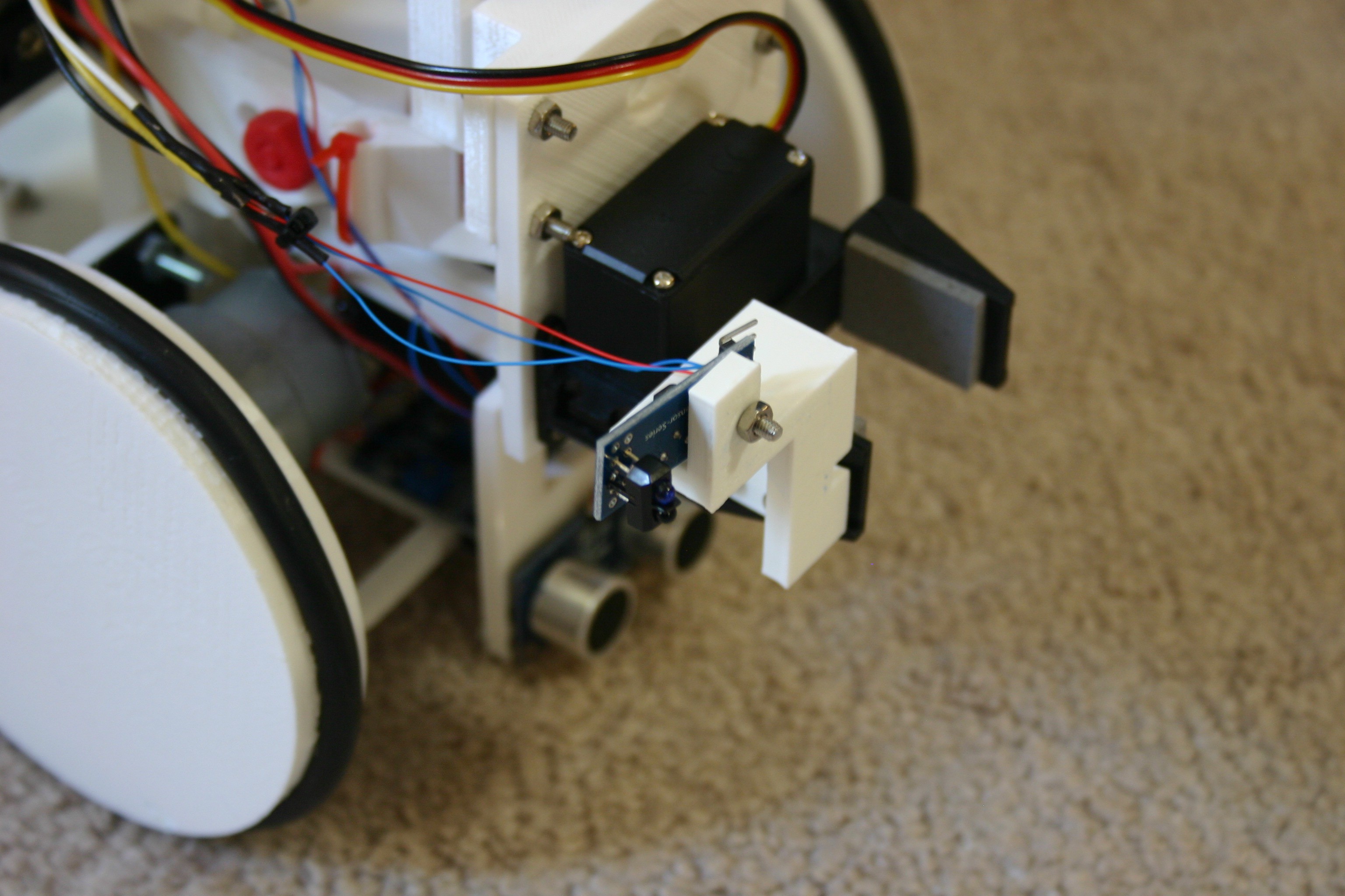
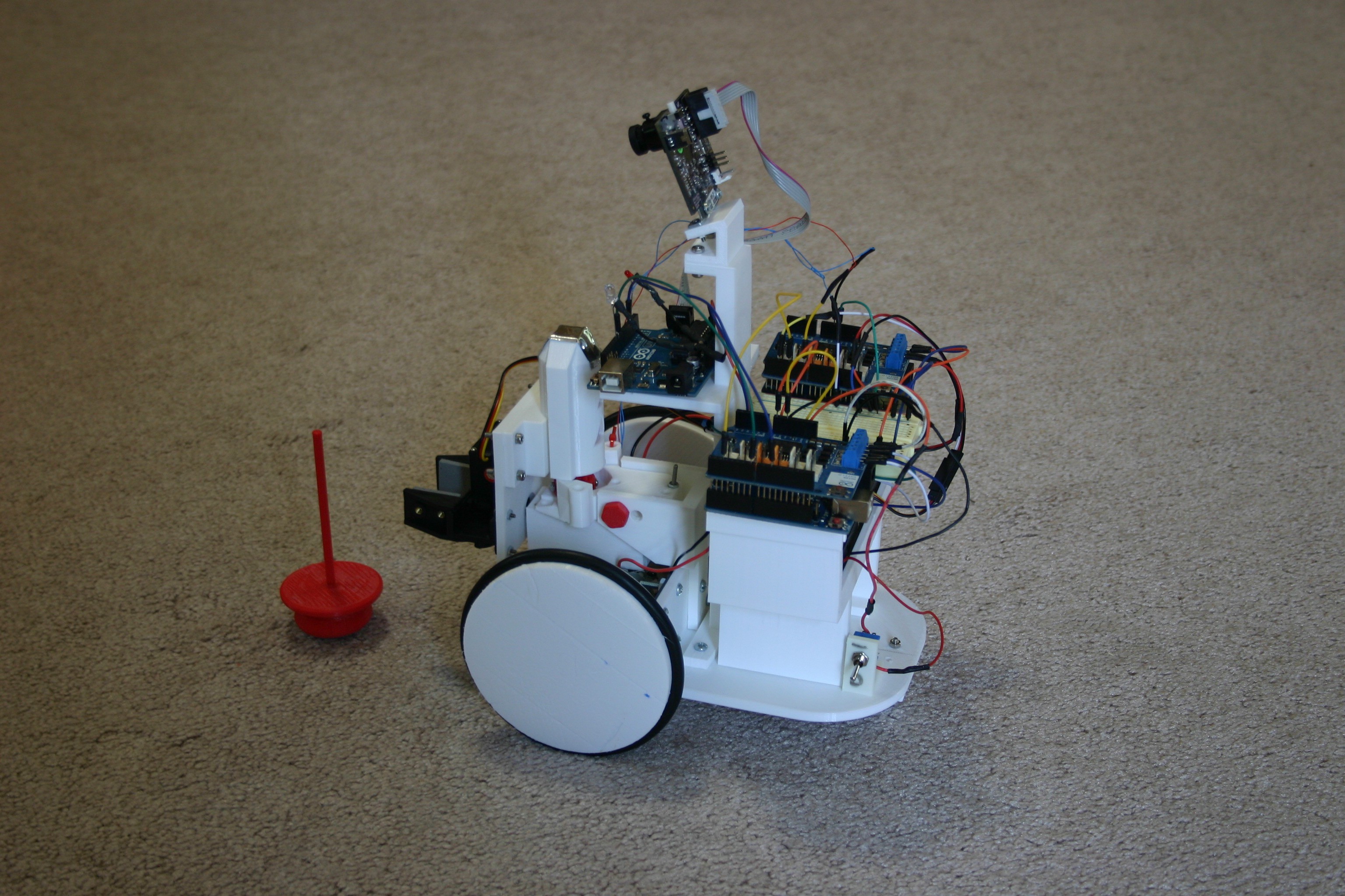
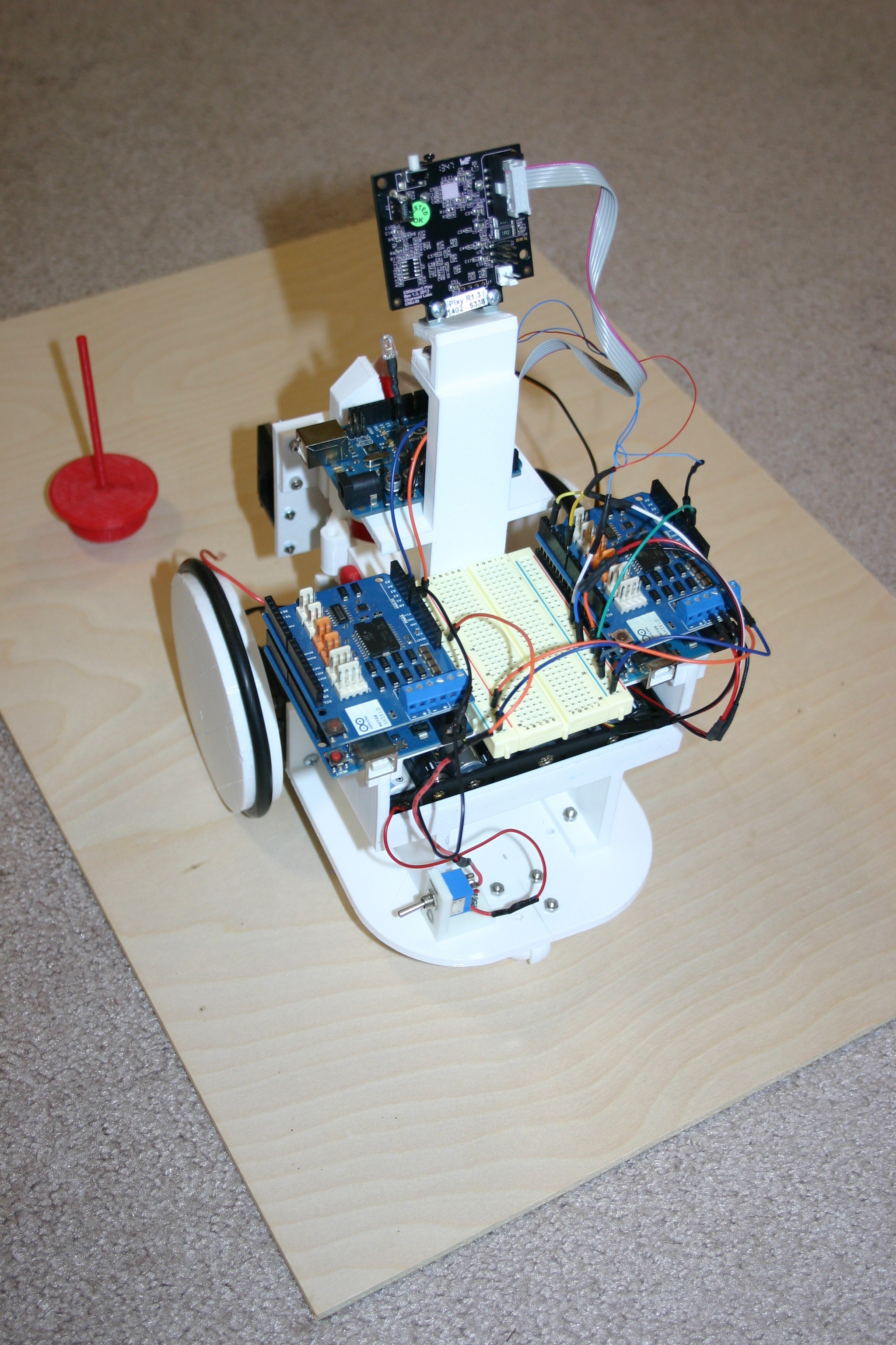
It works! Not yet clean or refined, but the catapult "gets rid of" the thing and the robot "brings it back."
0%
0%
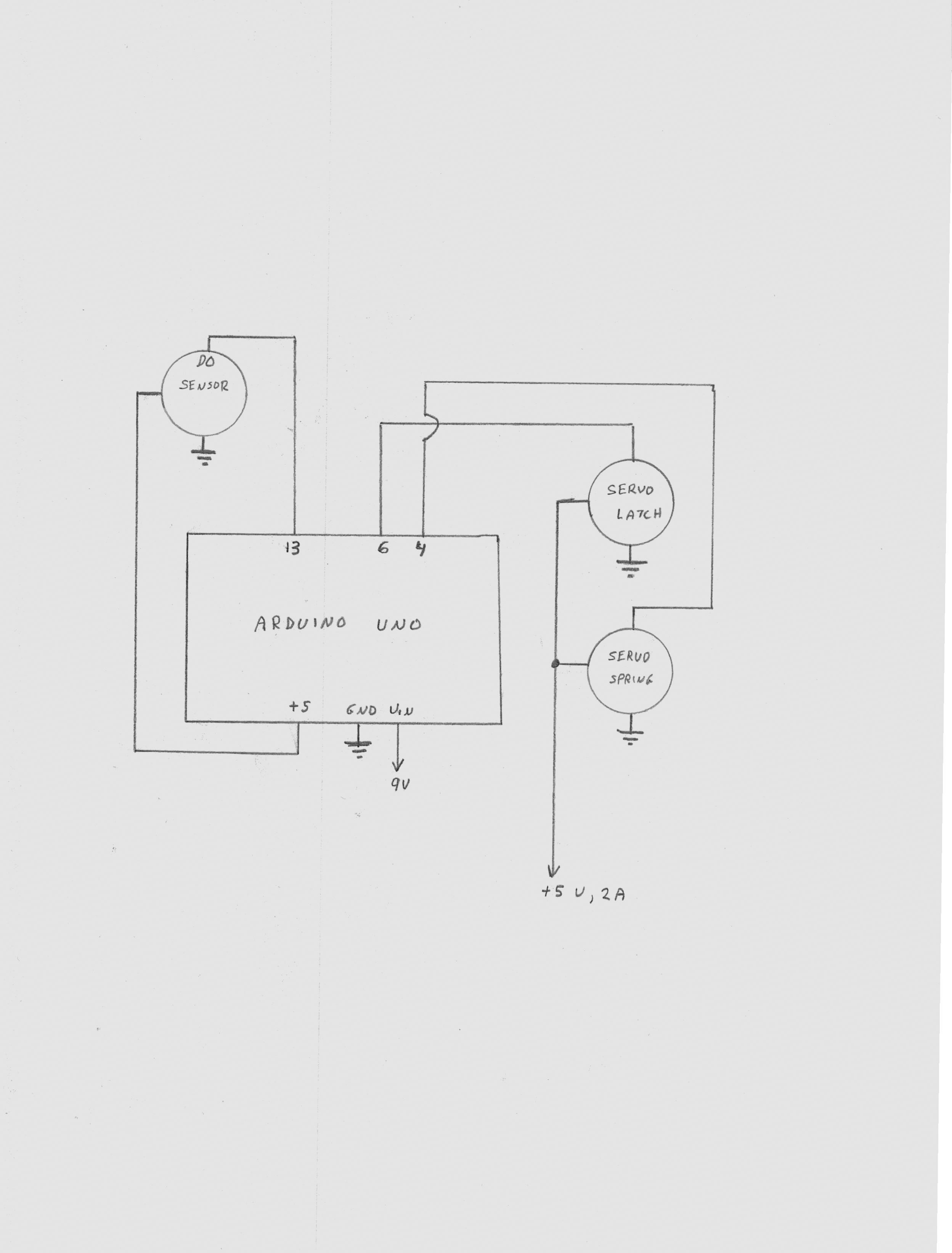
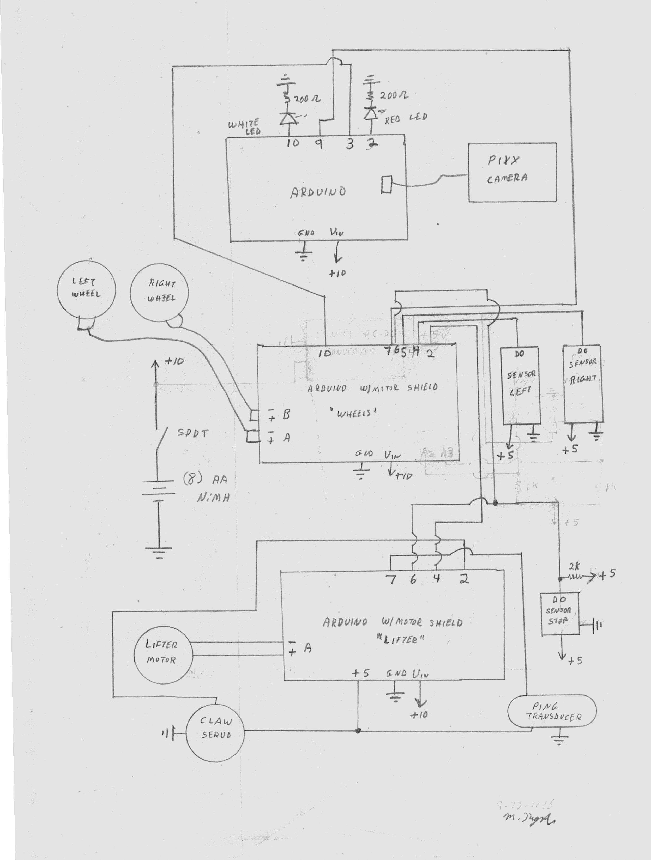
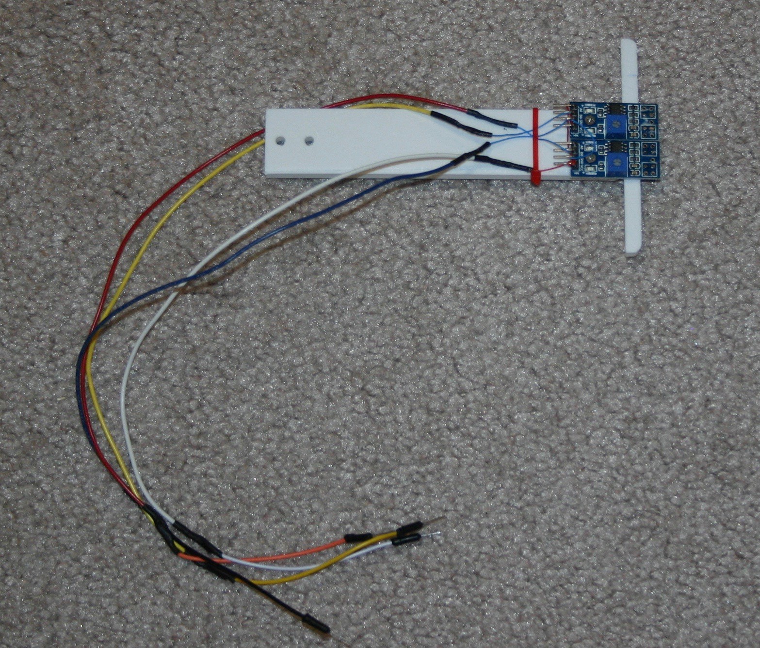
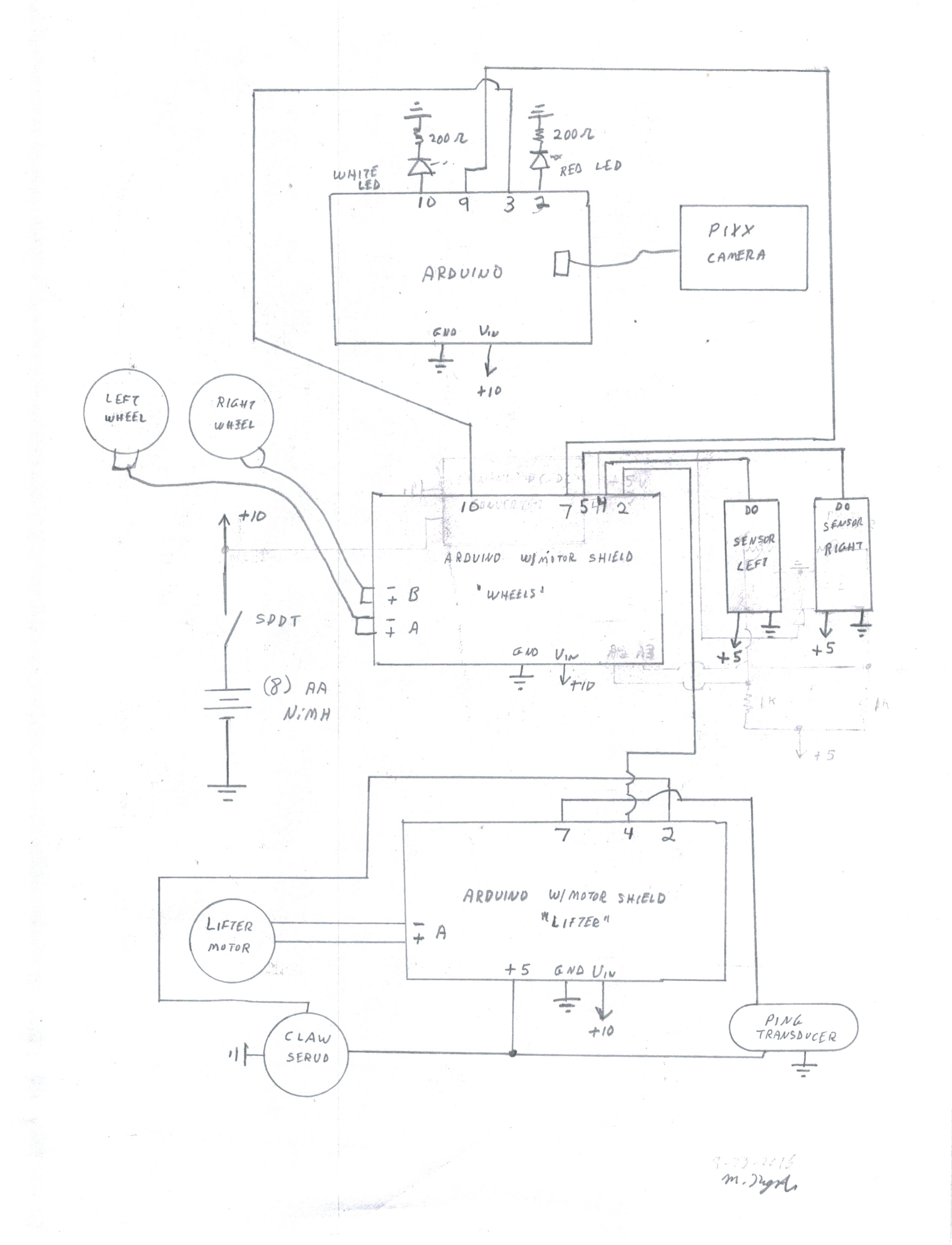
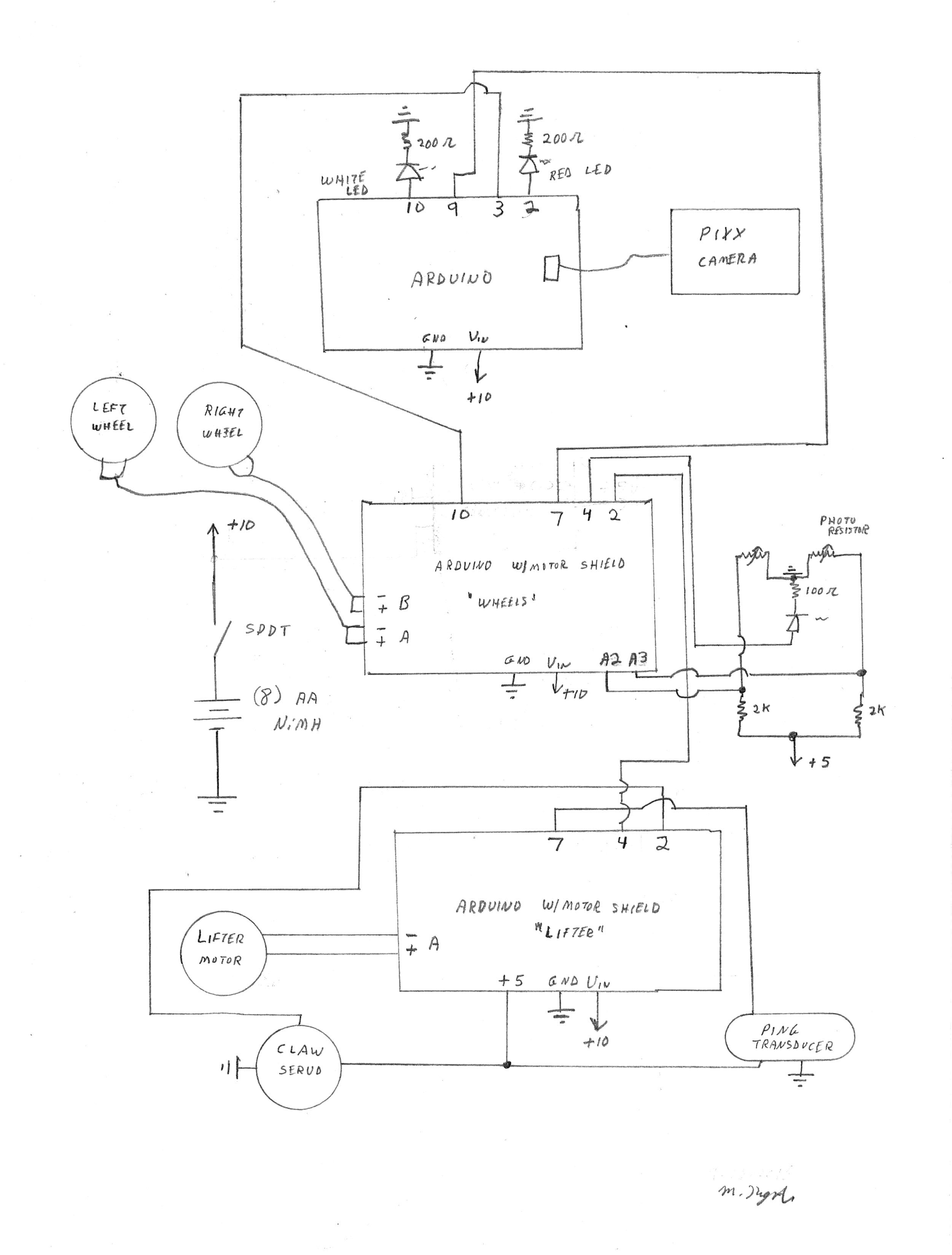
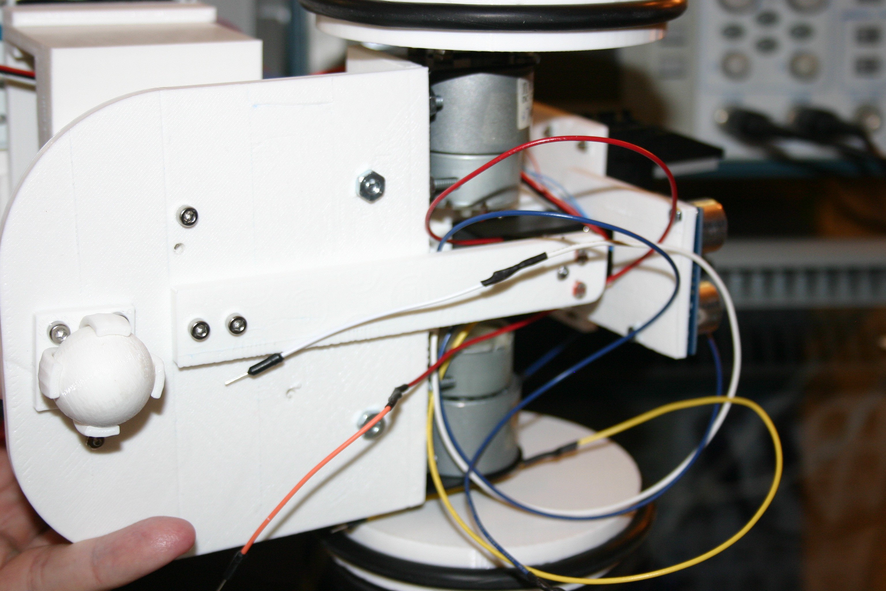
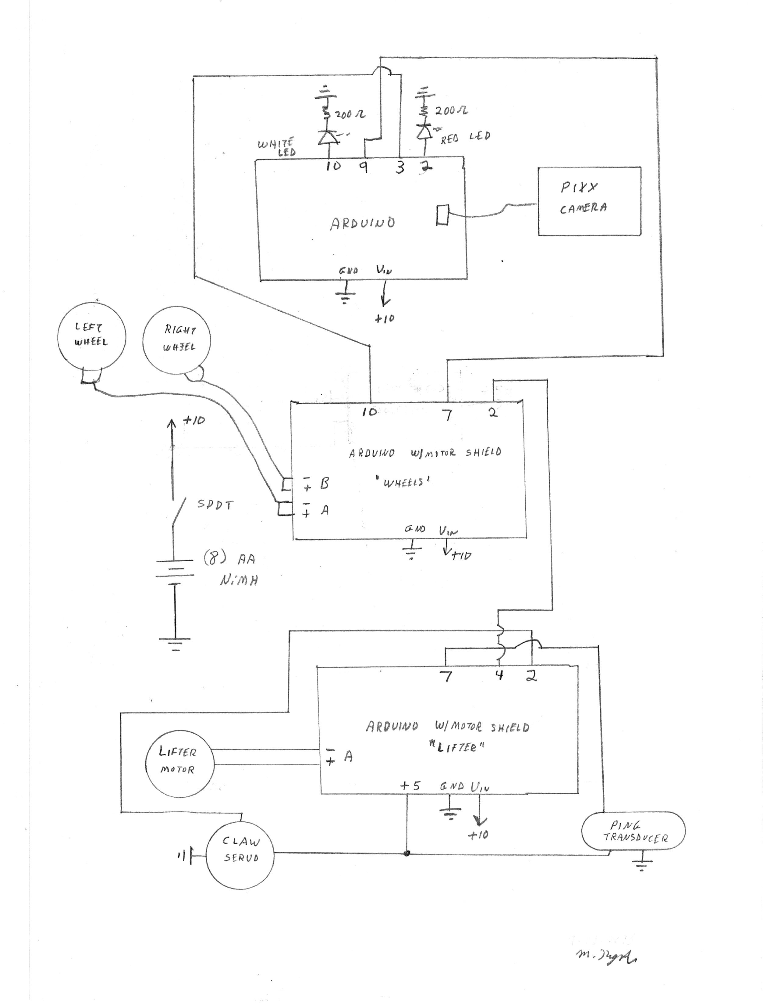
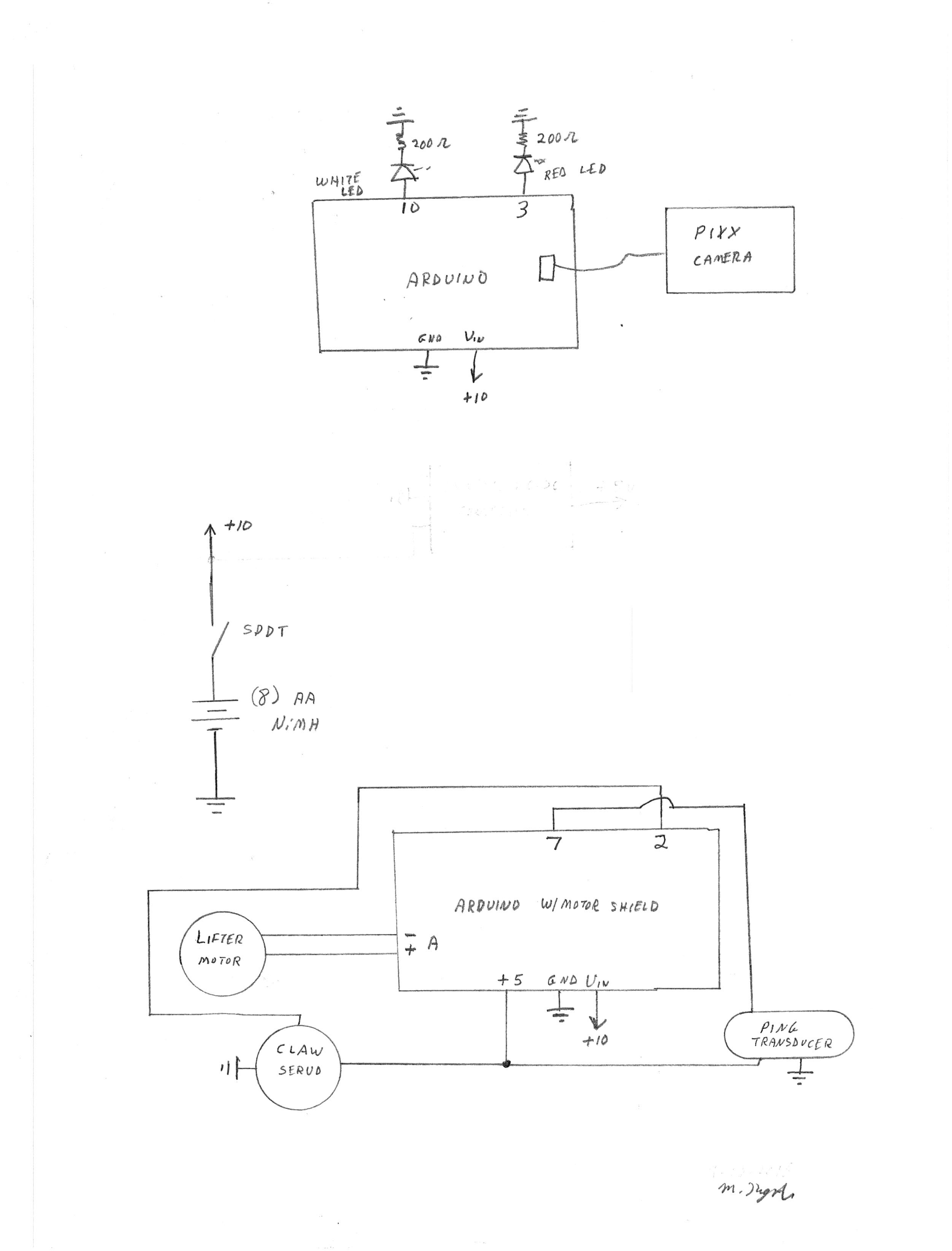
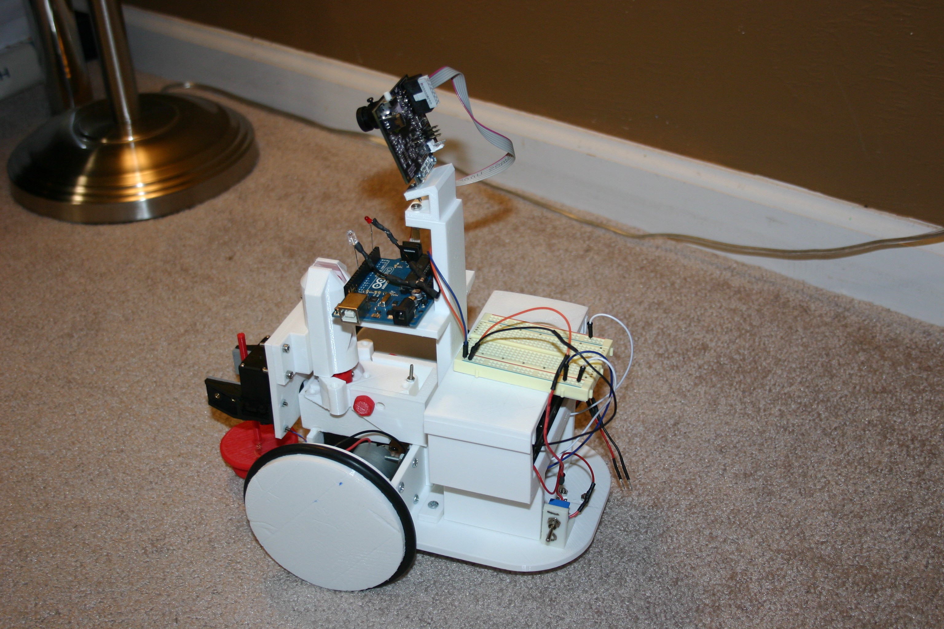
Pretty Useless Machine
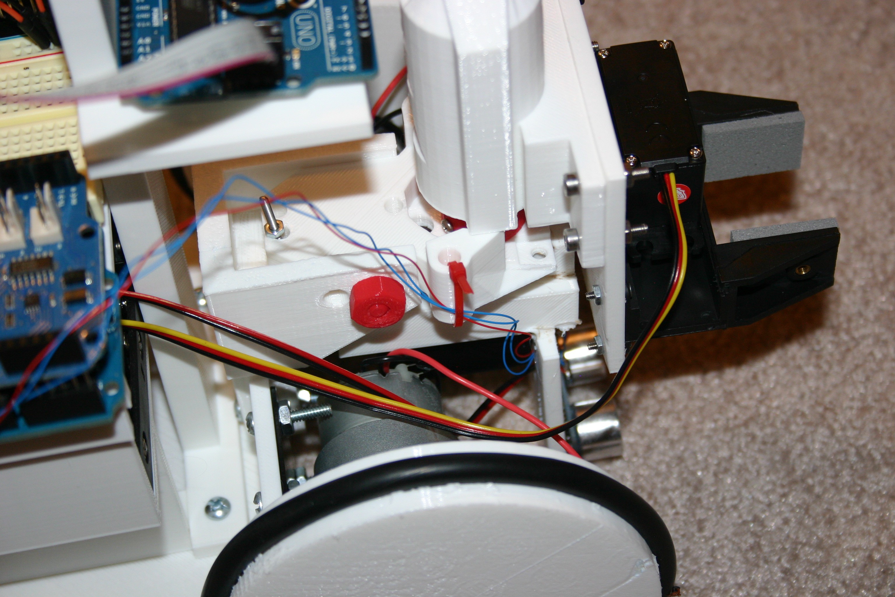
Fling the thing with a catapult, find it, bring it back, repeat.
Become a Hackaday.io member
Already have an account? Log in.
Just one more thing
To make the experience fit your profile, pick a username and tell us what interests you.
Pick an awesome username
hackaday.io/
Your profile's URL: hackaday.io/username. Max 25 alphanumeric characters.
Pick a few interests
Projects that share your interests
People that share your interests
 shamylmansoor
 BoneConstructor
 Shawn Chen