Mike Rigsby
-
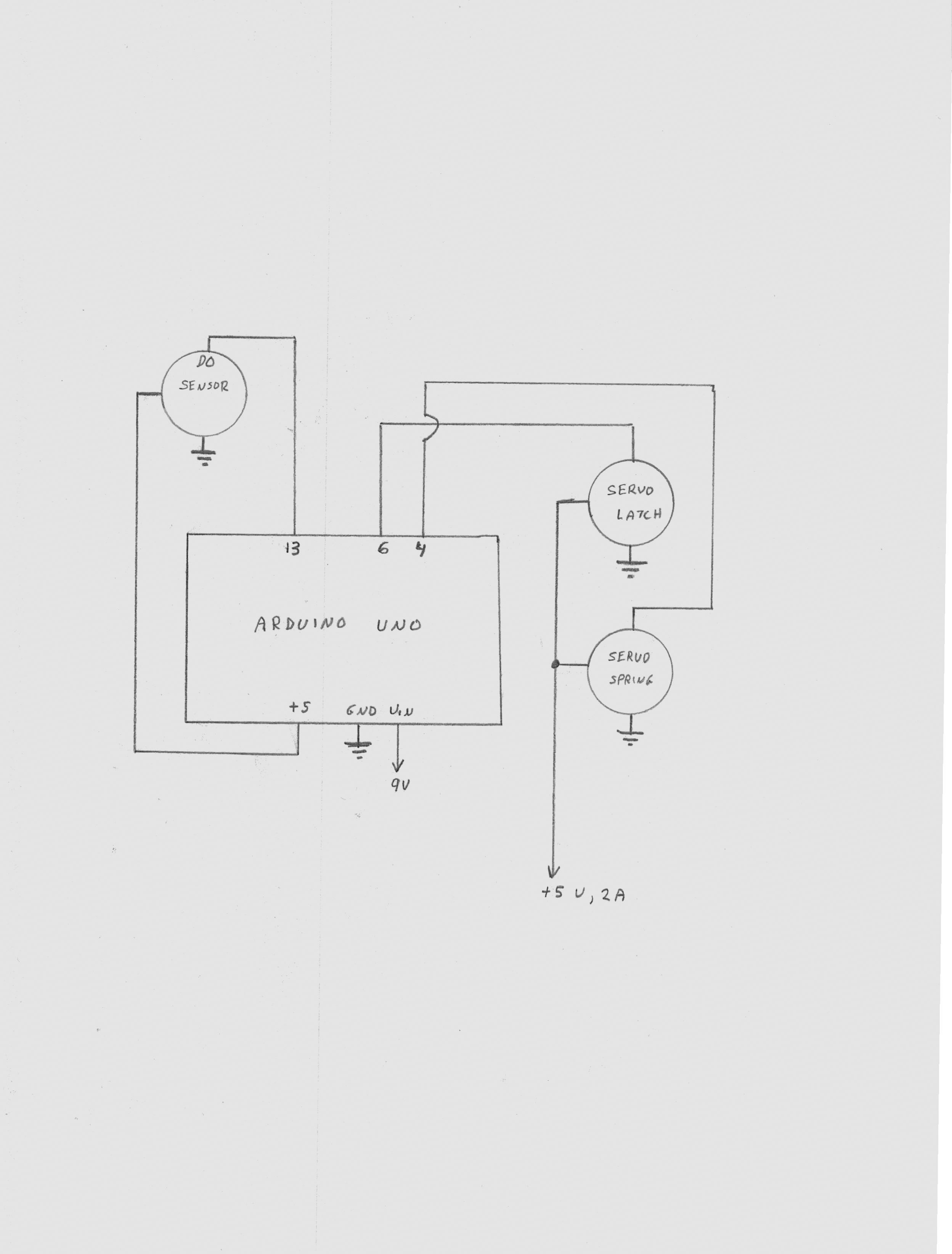
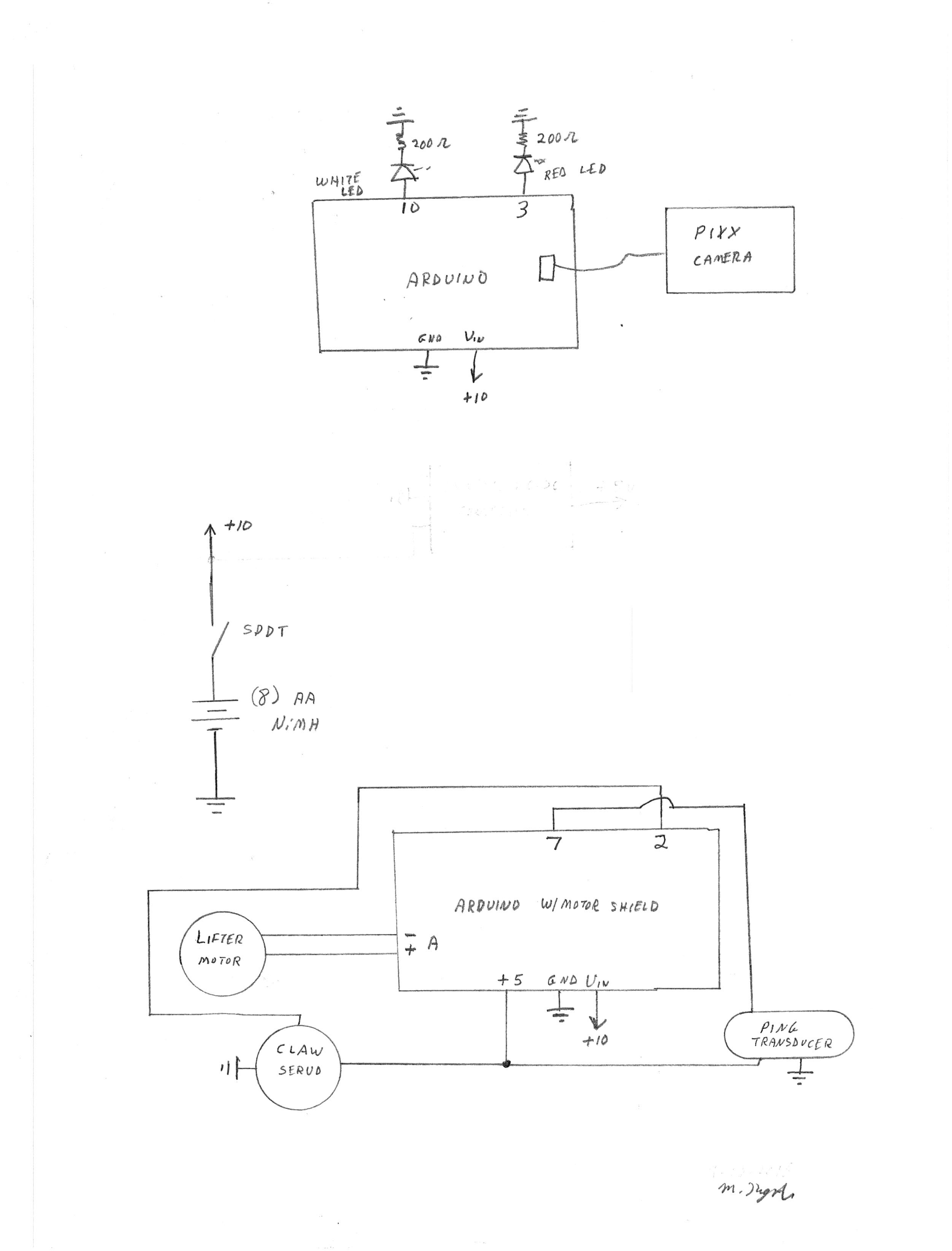
Catapult Schematic
11/05/2016 at 19:42 • 0 commentsHere's the schematic for the catapult:
![]()
-
Return Home and Drop Object
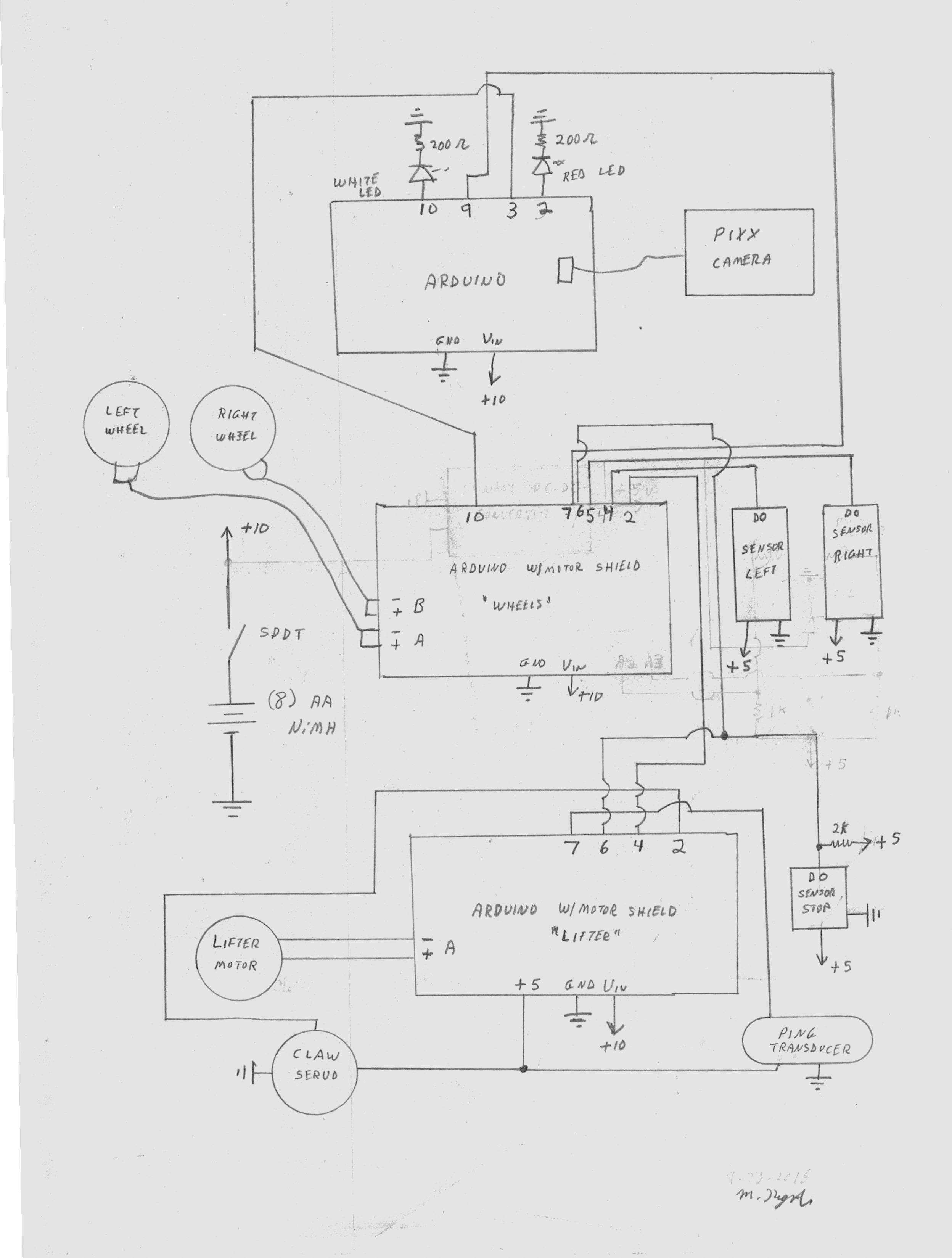
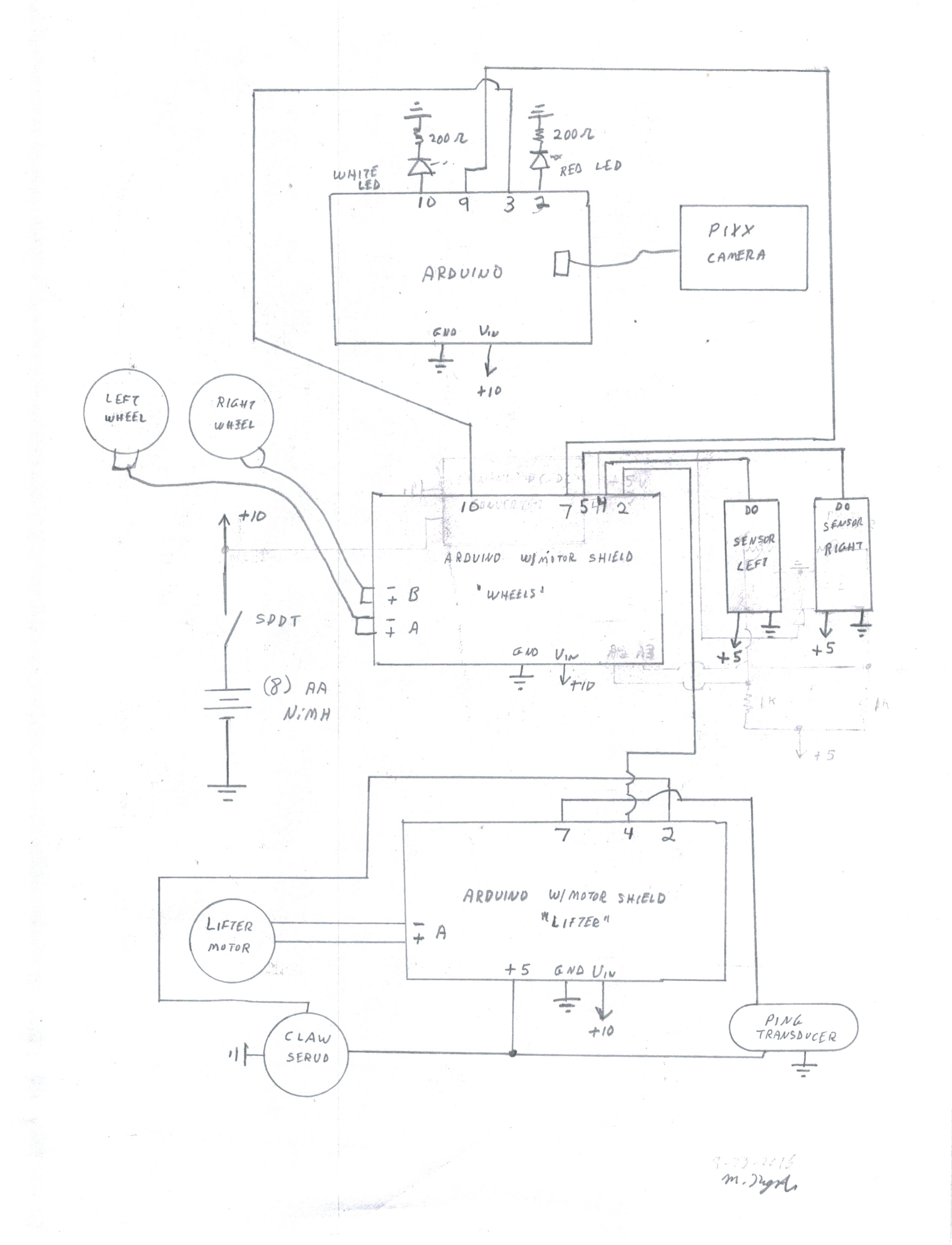
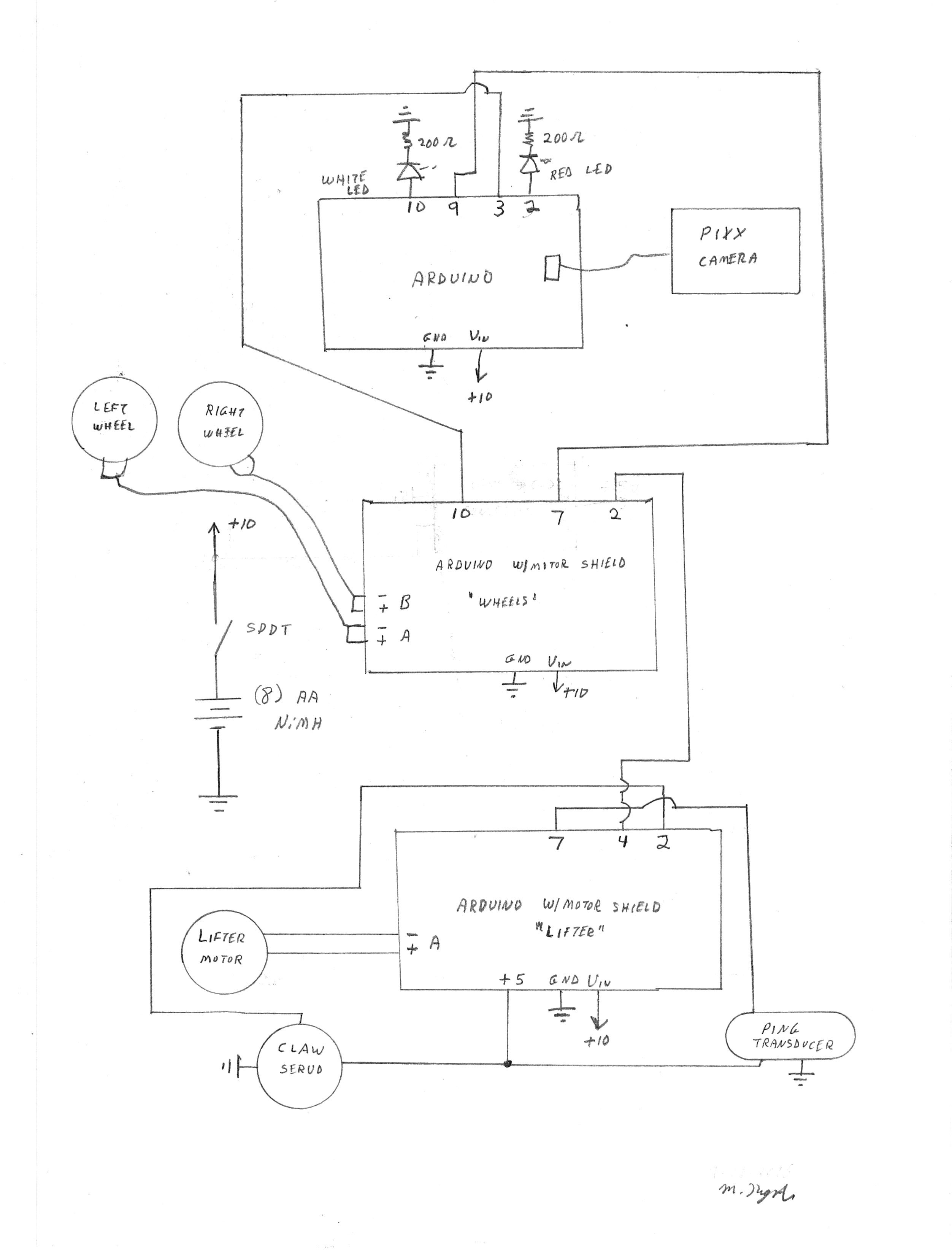
11/01/2016 at 18:46 • 0 commentsToday . . . the robot can find the object, pick it up, return home and reset for the next run.
An infrared sensor is used to detect the home location and sketch changes (documented on this site) modify the controls to make the robot perform its task. The latest schematic is below:
![]()
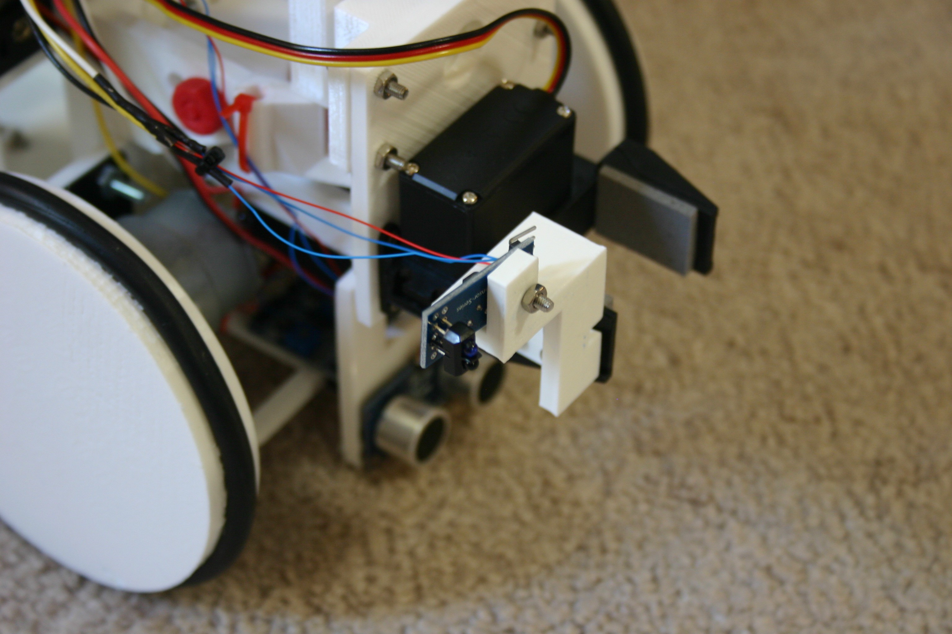
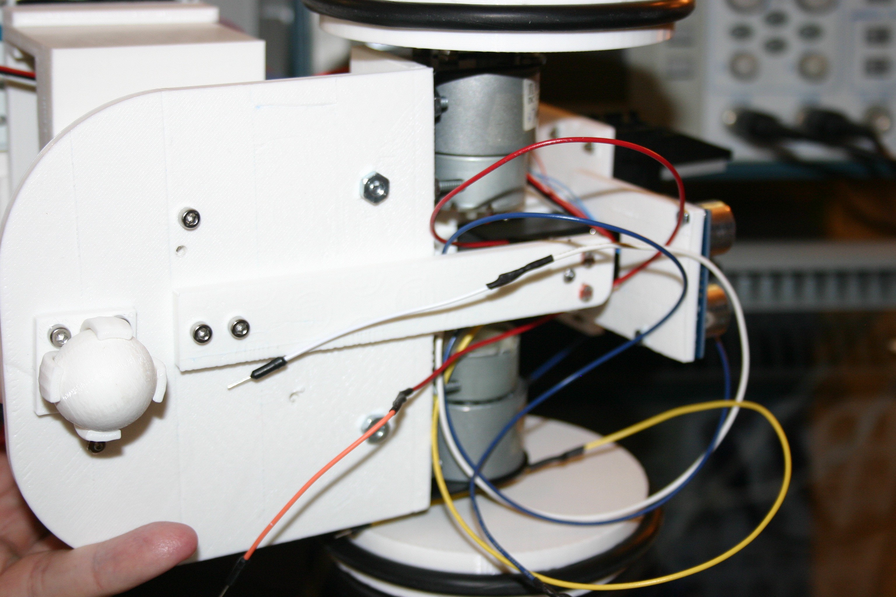
The "stop" sensor bracket (3d design and print files on this site) is secured to the claw using 3mm screws as shown below:
![]()
-
Finding the Line and Going Home
10/28/2016 at 19:48 • 0 commentsThe software sketch has been modified (1028) and is posted on this site. The robot now finds the object, then finds the line and tracks it back to the home position. The robot does not know that it is home . . . and time to drop the object and reset, but that's another day.
-
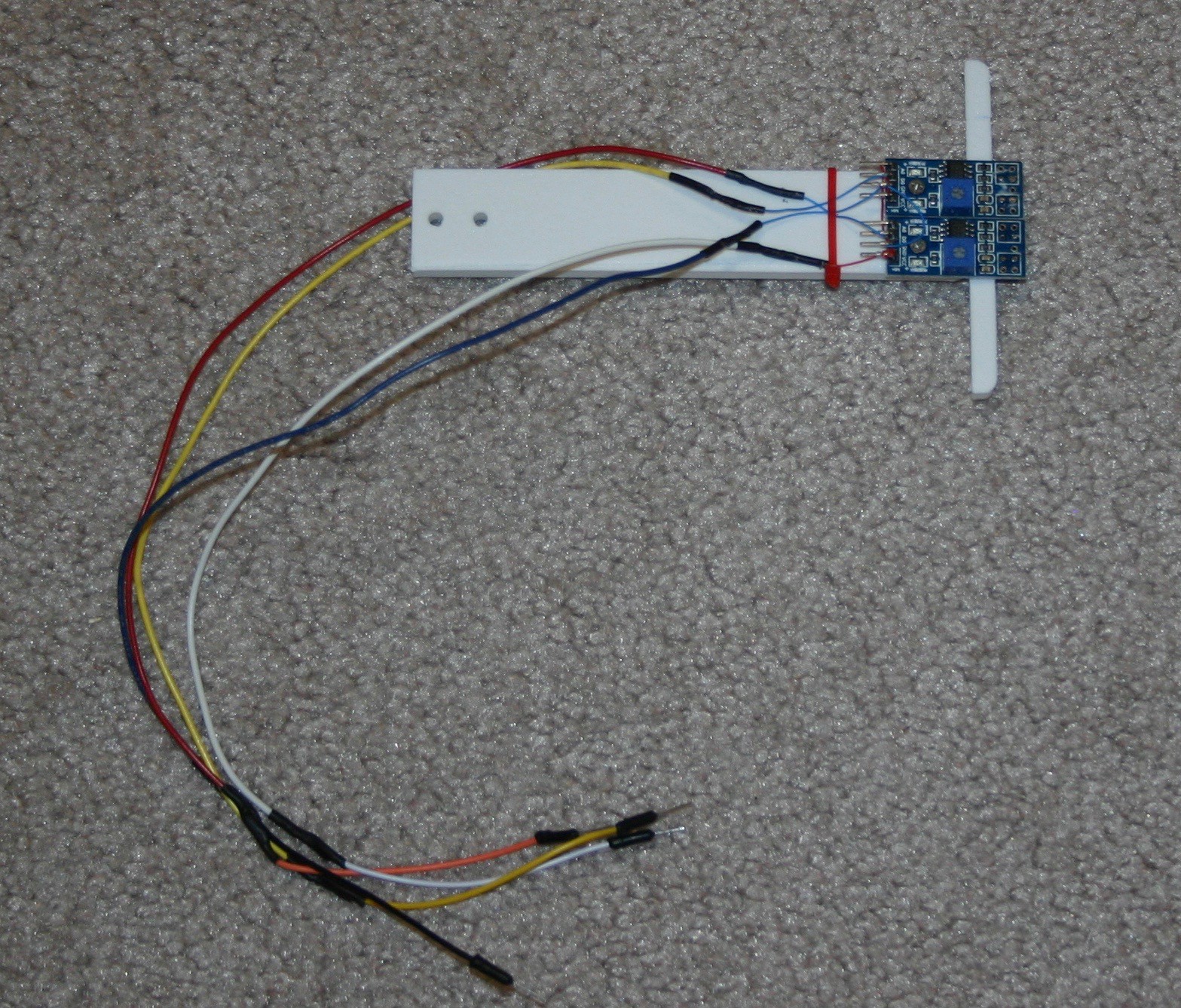
New Line Follow Mechanism
10/25/2016 at 20:09 • 0 commentsThe photocell arrangement for following lines just didn't work. I am now using infrared reflective sensors and the results are more promising.
The new bracket with sensors looks like this:
![]()
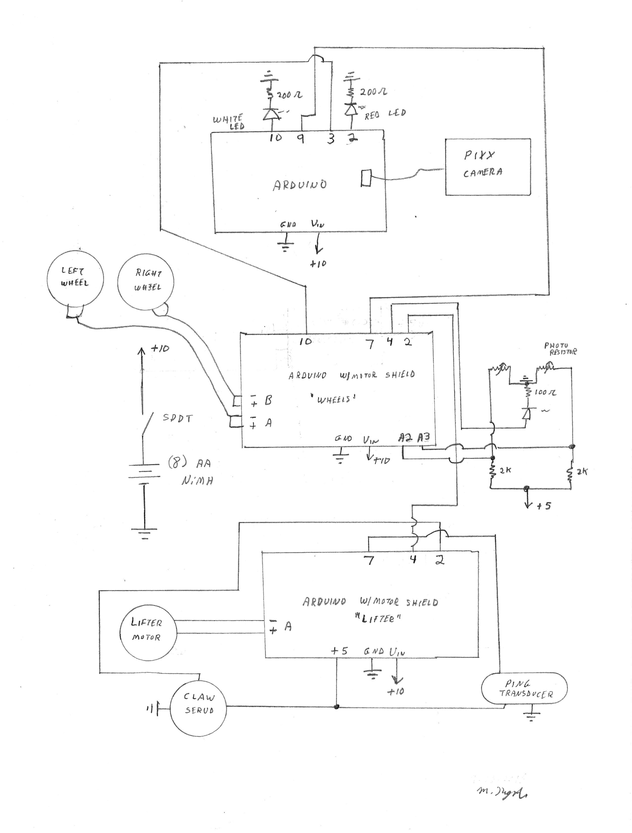
The wiring is done according to this schematic:
![]()
Following the line is not a problem, but detecting the line and latching on is giving me trouble--hence the wide black track.
-
Line Follow
10/07/2016 at 17:22 • 0 commentsI've started to add line following capabilities to the robot. This log will detail the hardware side. First, there's the schematic which includes the two photocells and an led light source.
![]()
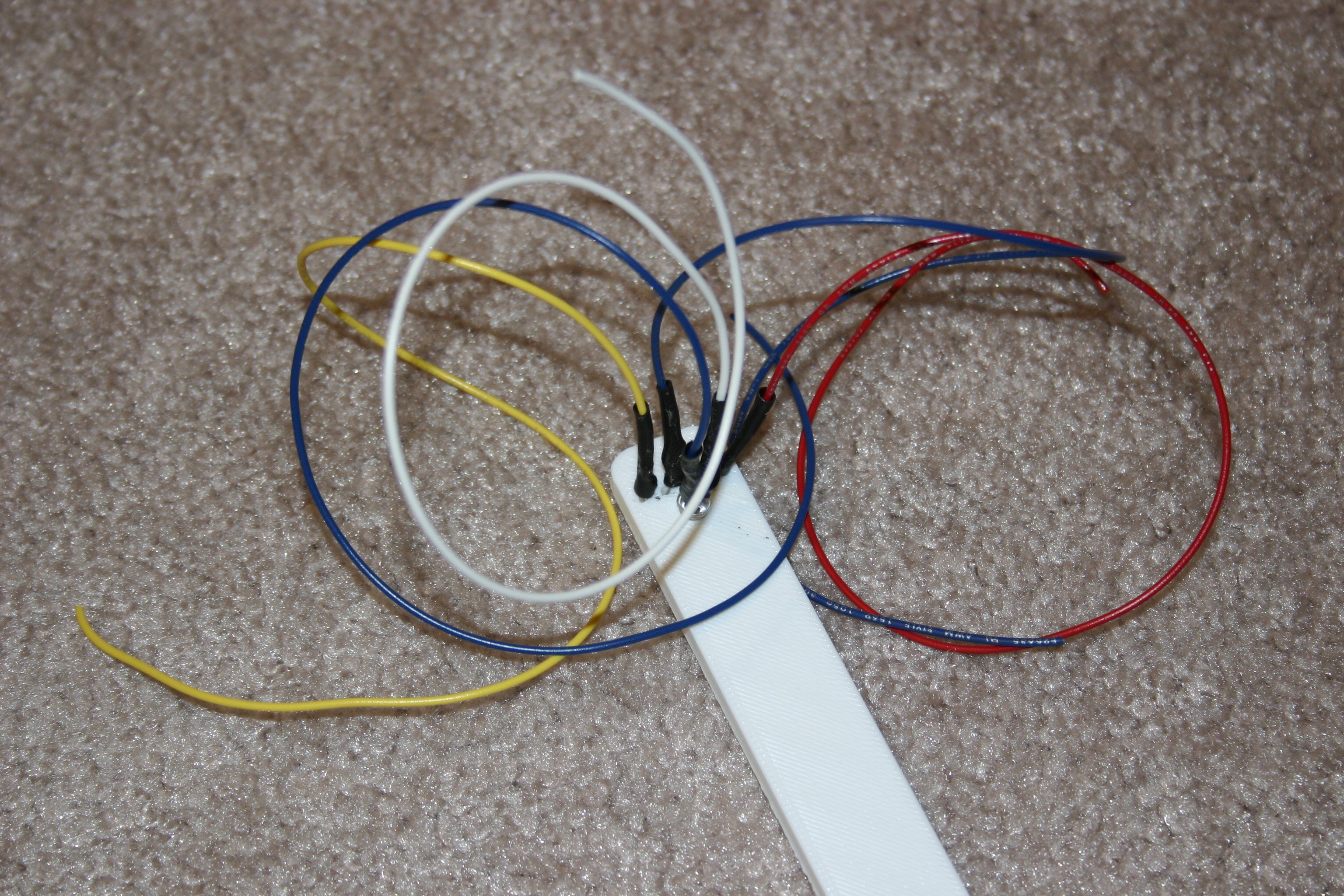
I designed a bracket to hold the line following electronics and that is called the "line follow bracket" (files included on this site). I inserted the parts and soldered wires (with heat shrink insulation) to the components.
![]()
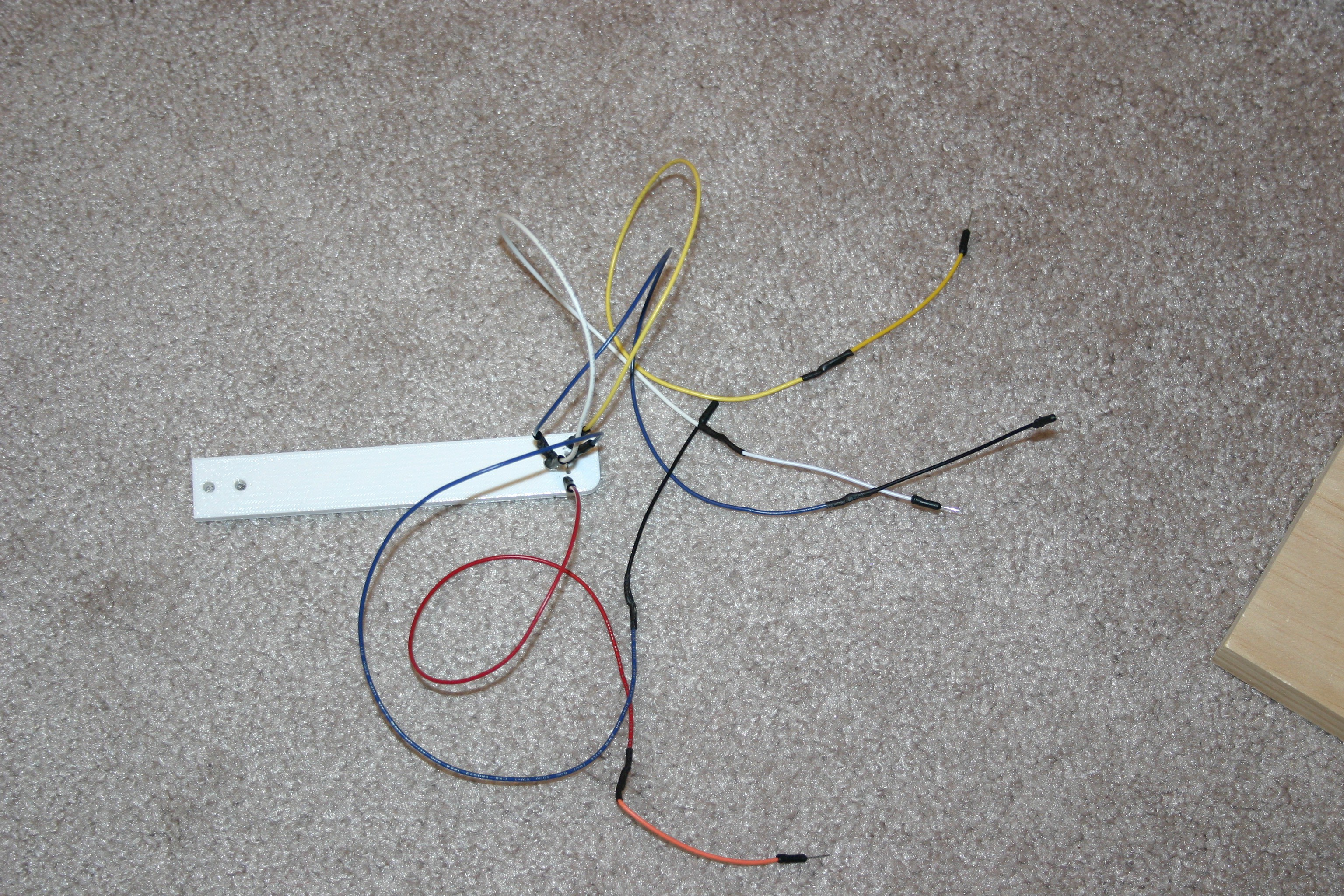
I soldered breadboard pins to the other end of the wires.
![]()
I drilled holes and mounted the arrangement on the bottom of the robot.
![]()
-
Dealing With Obstacles
10/04/2016 at 19:02 • 0 commentsI built a box (42 inches by 54 inches--3.5 inches high) to confine the Fetch system. Software is now in place so that the robot can find the object, but also recover if it bumps against a wall or other obstacle.
Next, I'll have to add some line following hardware and software so that the robot can follow a line back to the catapult.
-
Retrieve
09/26/2016 at 19:41 • 0 commentsNow it is possible to throw an object using the catapult--details here.
The current state of the project allows me to throw the "thing" using the catapult (by pushing a button remotely) and have the robot (standing by in ready mode) chase and retrieve the thing. The robot then backs up and drops the object.
Obstacle avoidance and getting back to the catapult flipper have yet to be implemented.
-
Fetching
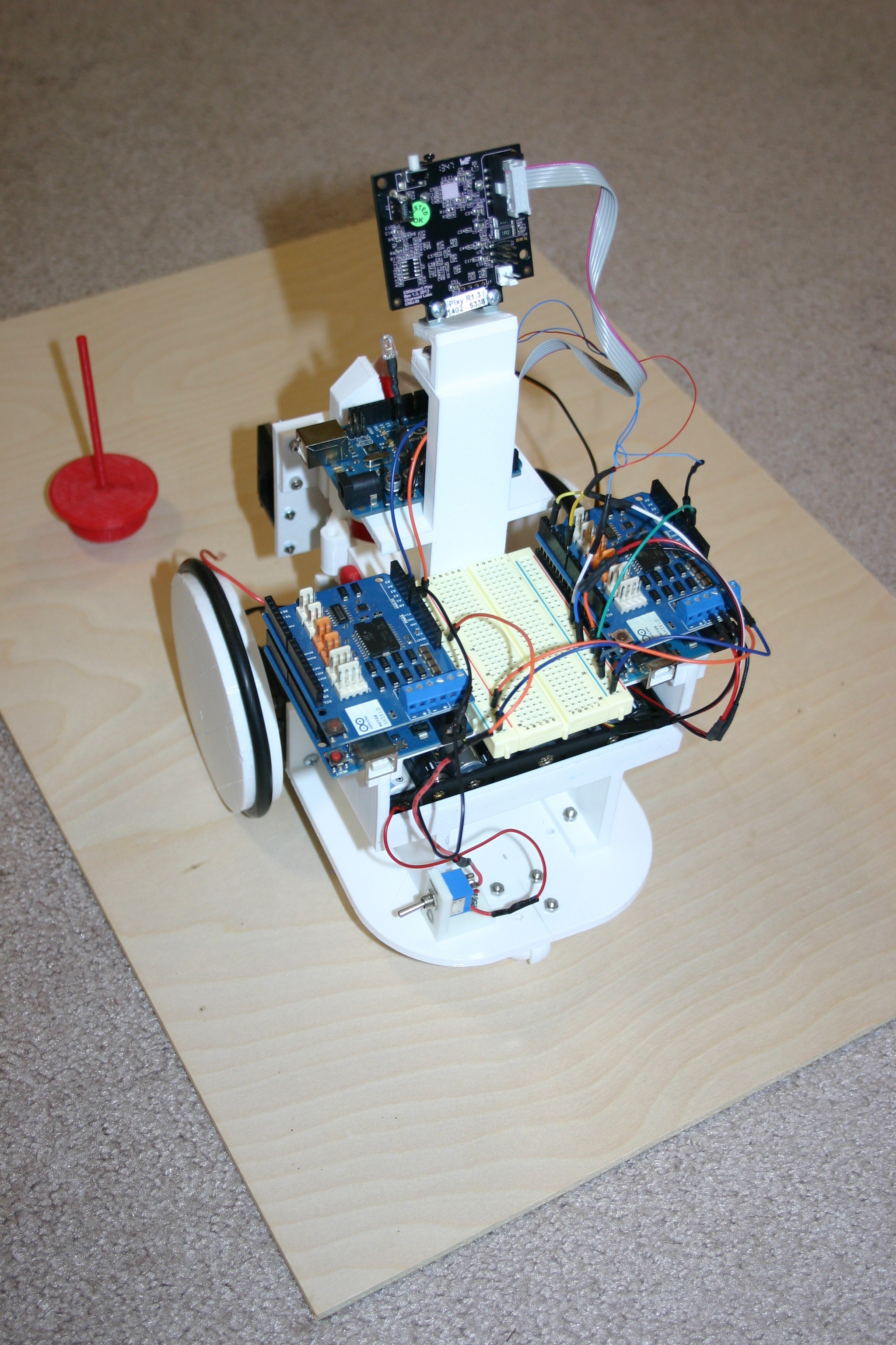
09/25/2016 at 18:22 • 0 commentsNow the robot will seek the target "thing" and lift it off the ground.
This is accomplished by using the vision controller, ping controller and motor controller.
![]()
Wire as shown in the schematic and install the Arduino sketches (available on this site).
![]()
-
Detect "Thing" and Lift It
09/24/2016 at 16:47 • 0 commentsNow the Ping detector finds the thing, the claw grabs it, lifts it, then drops it and lowers. I still do not have the wheel motors hooked up yet.
Here's the current schematic
![]()
I had to remove the DC to DC converter because it created electrical noise that prevented the Arduino from operating properly. I did not have such problems with Mato, but Mato's 9000 farads of capacitance probably had a damping effect on electrical noise. The ping controller sketch for the Arduino is available on this site.
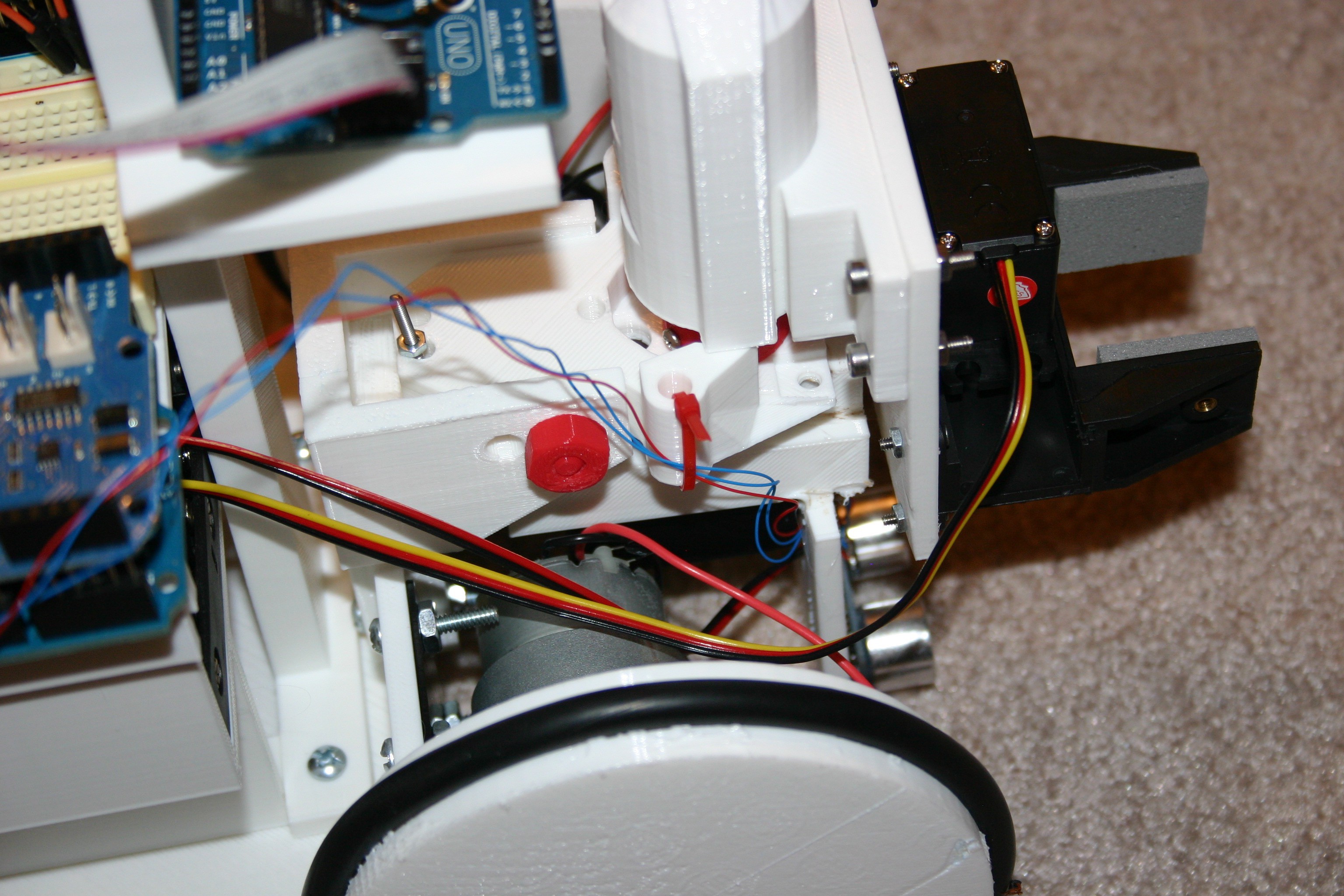
I secured the ping wires to the lifter using a tie wrap--to prevent them from getting into the wheels.
![]()
The rest of the connections are made primarily with jumper wires.
![]()
-
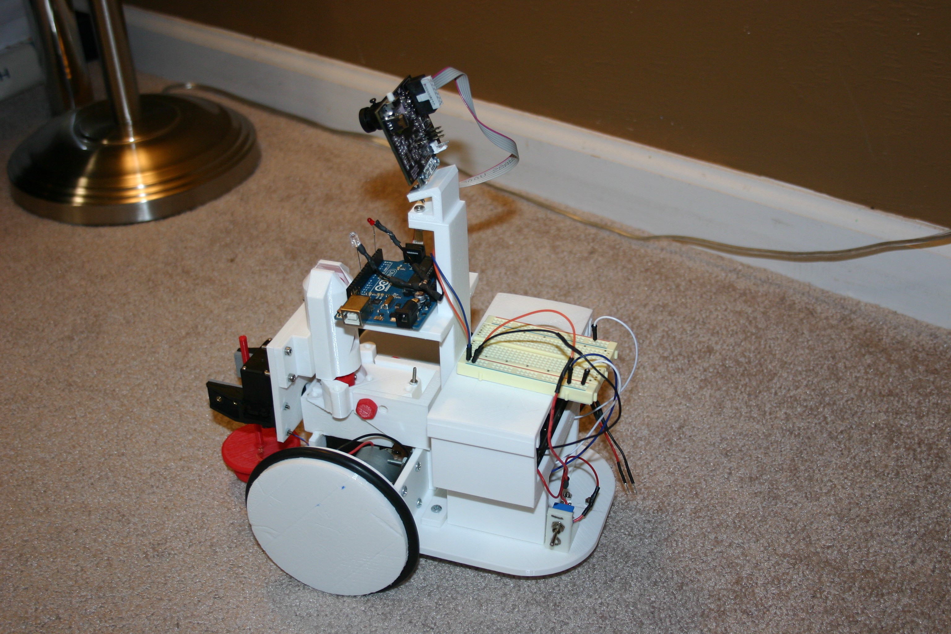
Vision for the Fetching Robot
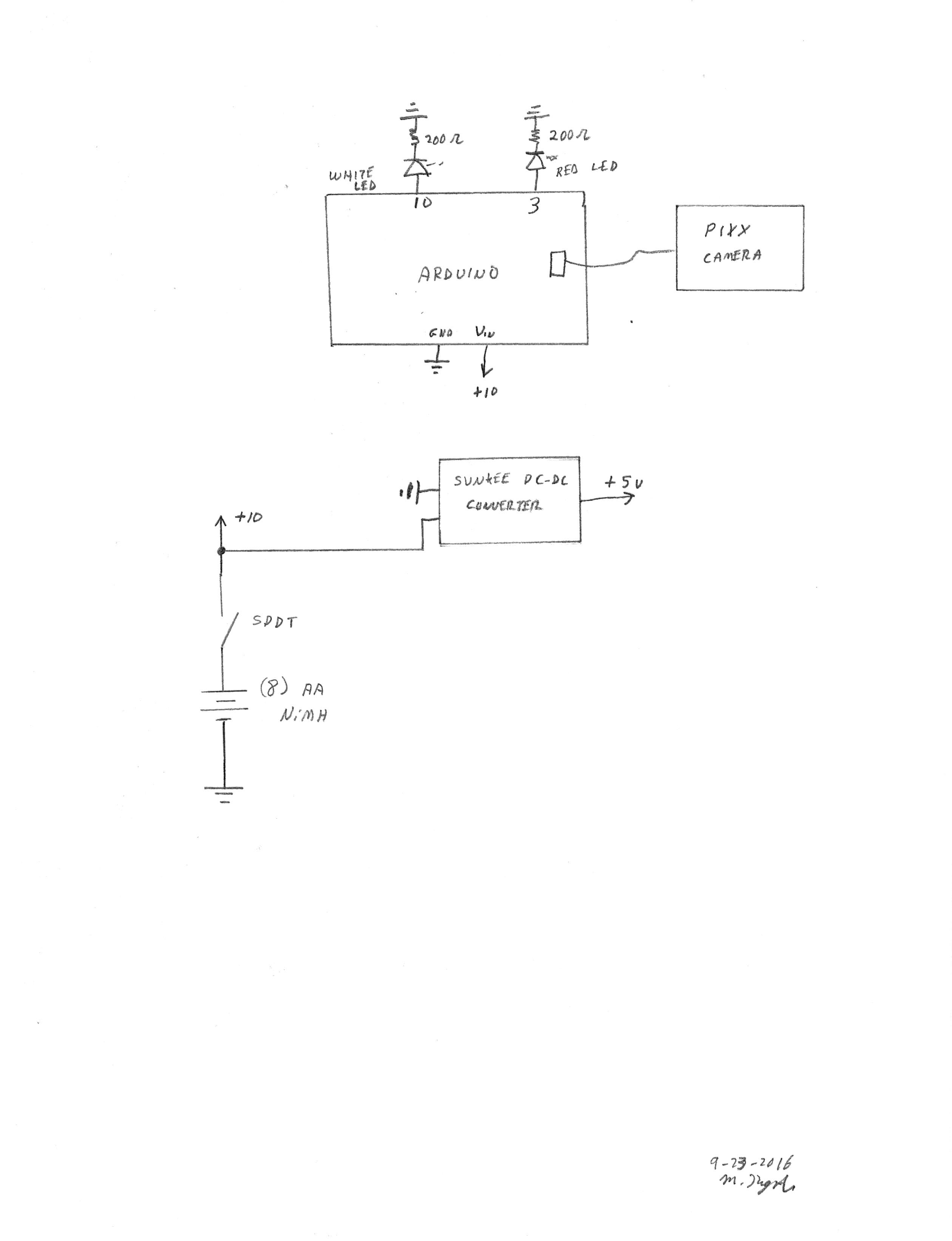
09/23/2016 at 17:36 • 0 commentsIn this step, I'm adding power and vision capability for the robot. Let's examine the operation of the vision system. Pixy is trained to a color--push the white button on top until the Pixy LED turns red then release. Place the target color (my red wobbler "thing") in front of the lens until the LED turns more or less the color of the target "thing". Press the white button and release--the LED should flash to indicate acceptance. The Pixy camera detects color blobs (providing location information about them) and works best in a controlled light environment. In other words, if the light source changes, Pixy will have trouble seeing the selected color--Pixy is trained to a color/light source combination.
In my setup, the red led (attached to the Arduino) blinks when the object is to the right. The white led blinks when it is to the left. When straight ahead (or nothing visible), both led's are off.
Let's look at my example--I'm moving the robot by hand because the motor controls are not enabled yet.
The vision sketch for the Arduino is available on this site.
Here's the schematic:
![]()
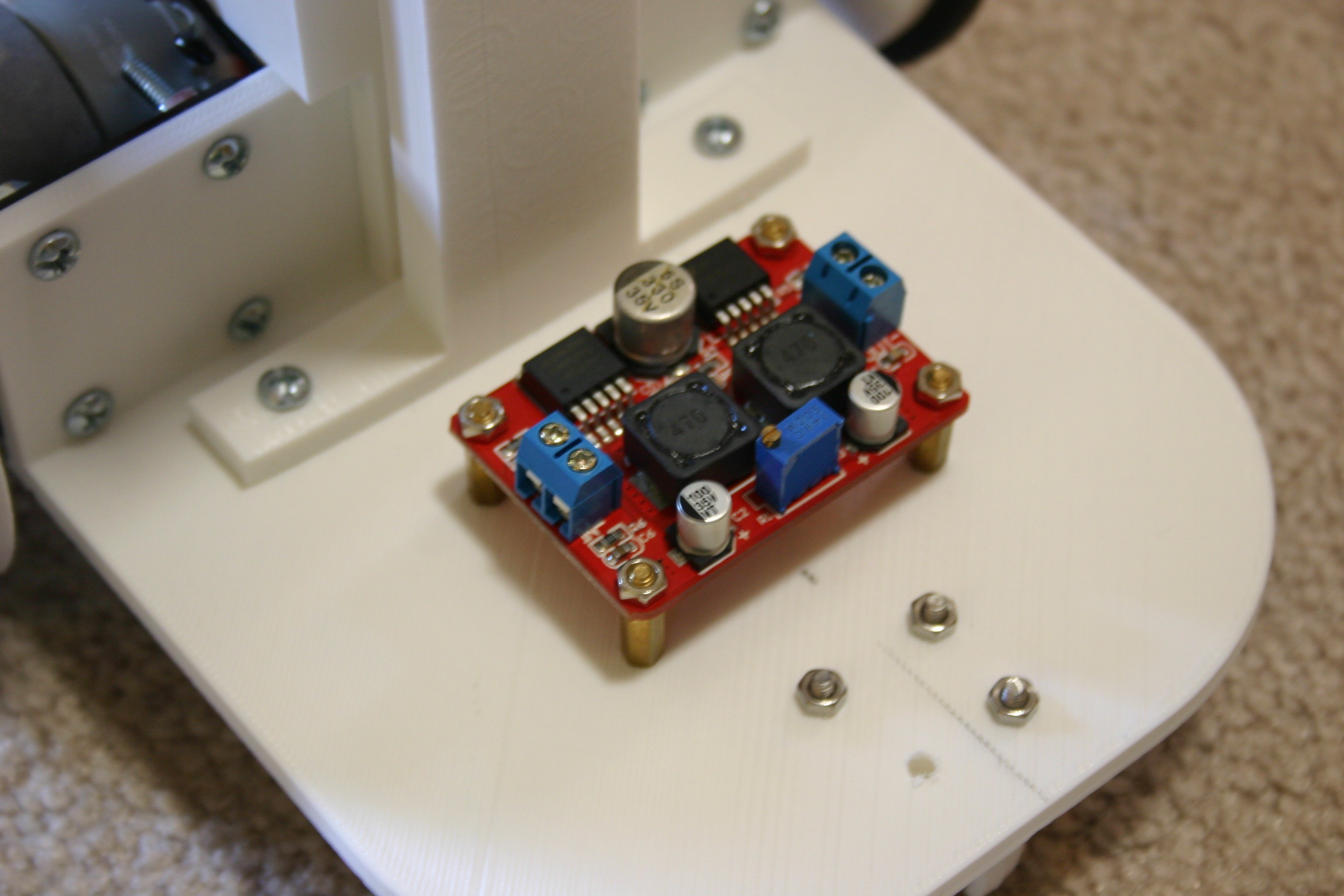
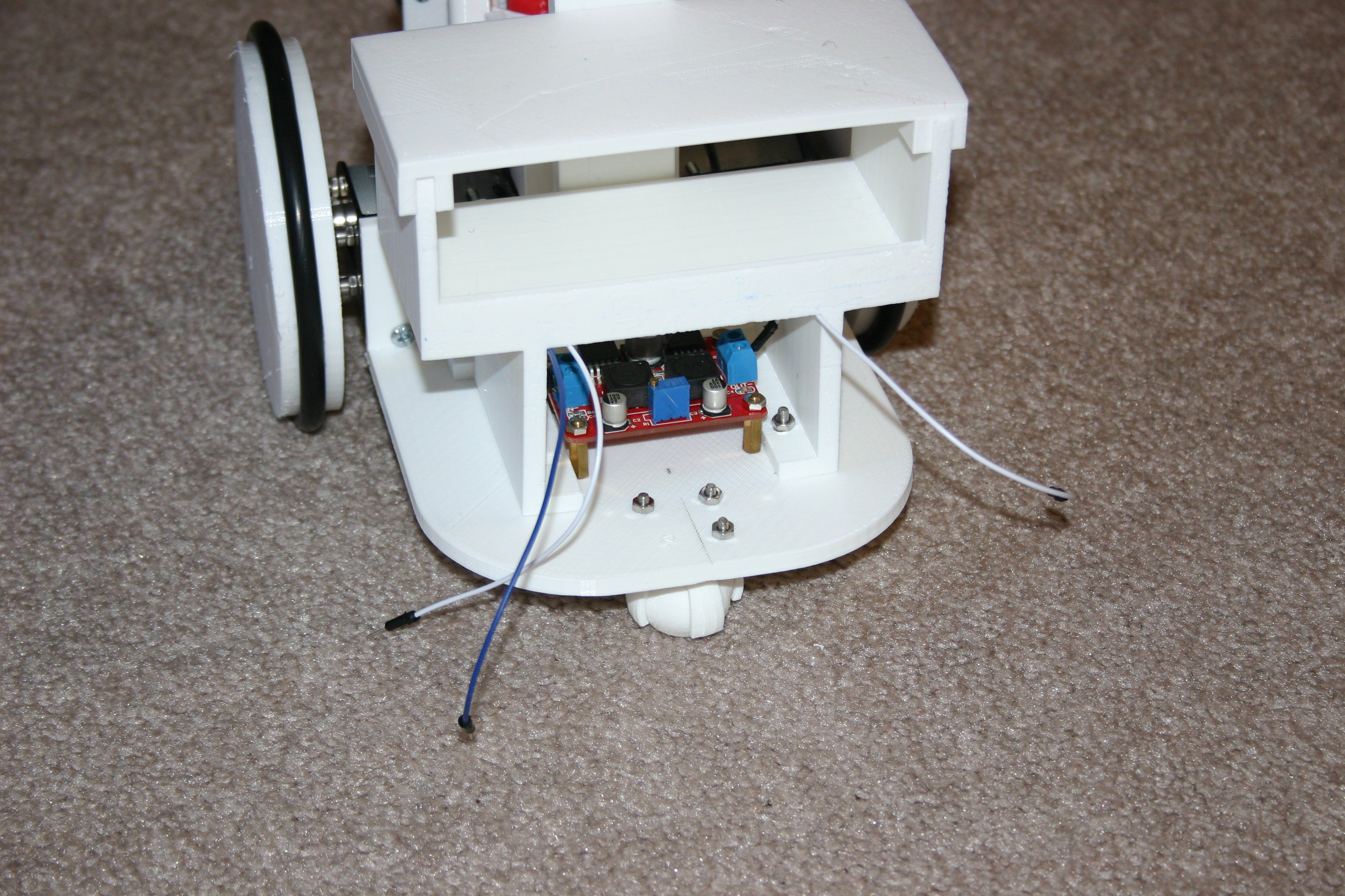
Here's the DC-DC converter attached to the robot base. This will supply 5 volt power for the servo motor (I may add a "tail wagging" servo later).
![]()
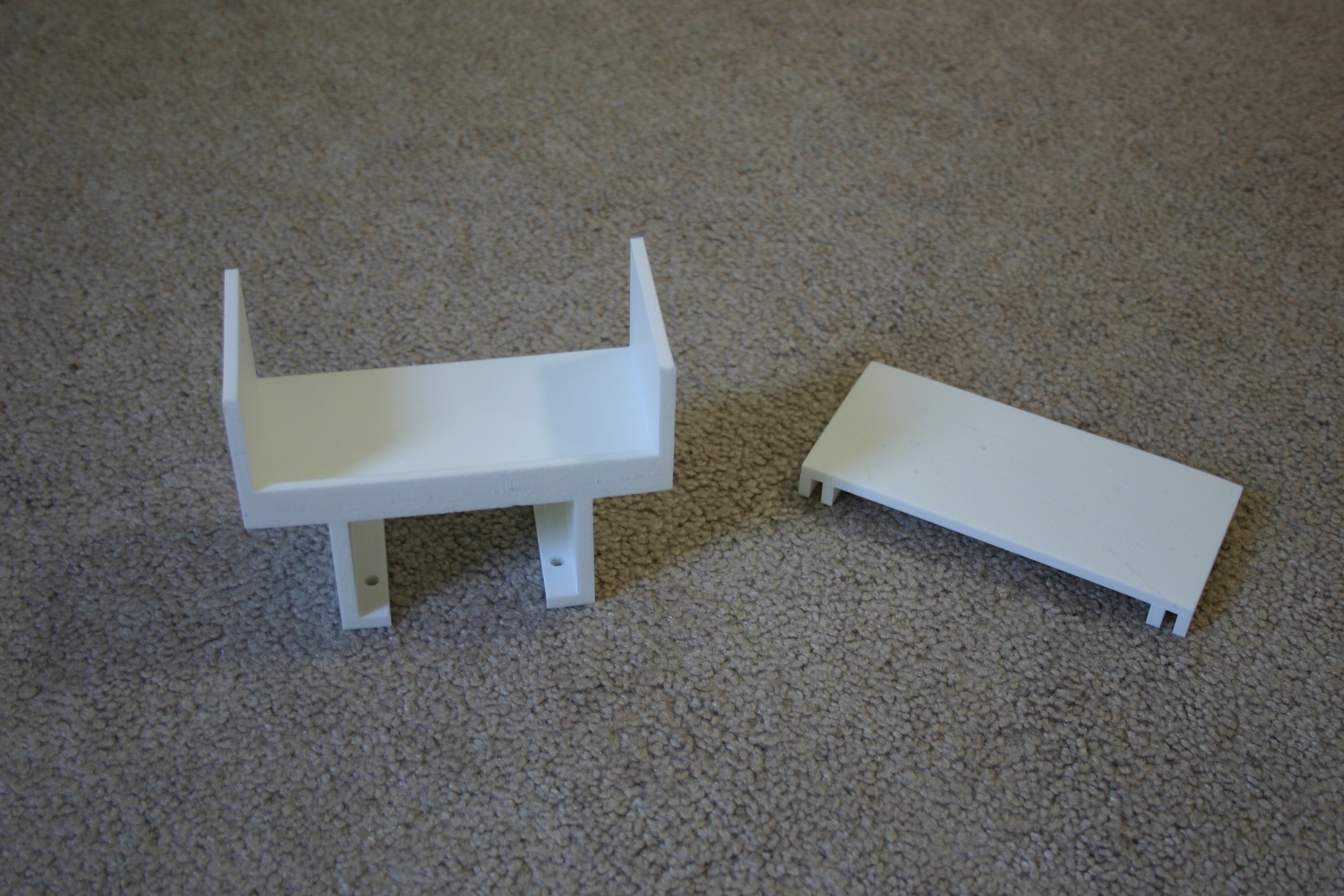
I printed the battery holder bracket and Arduino holder platform (files available on this site).
![]()
Connect the input and output terminals of the DC converter before attaching the battery holder platform.
![]()
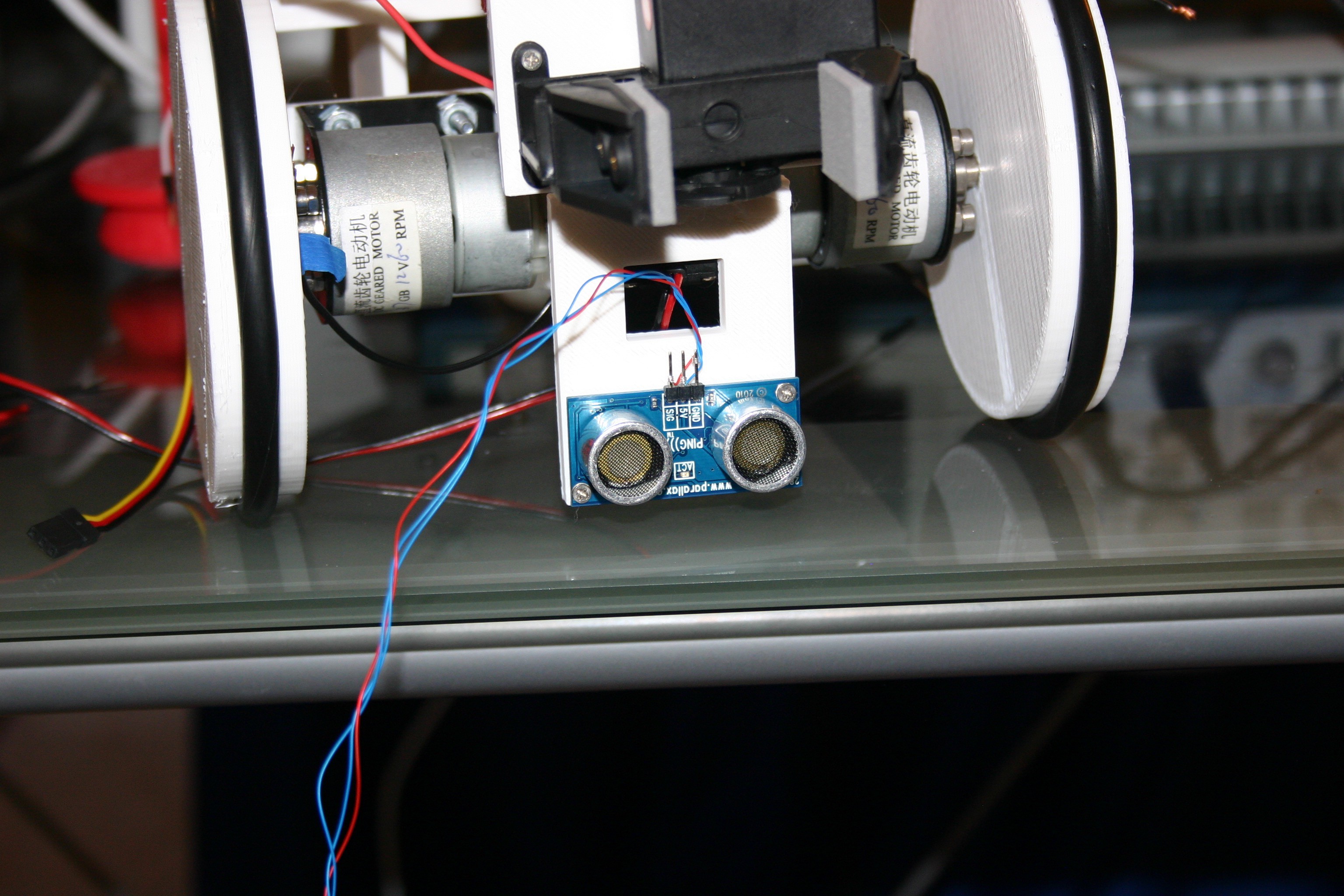
Remove the ping transducer and attach wire wrap wires to the terminals, then replace the Ping transducer (we'll need this later on).
![]()
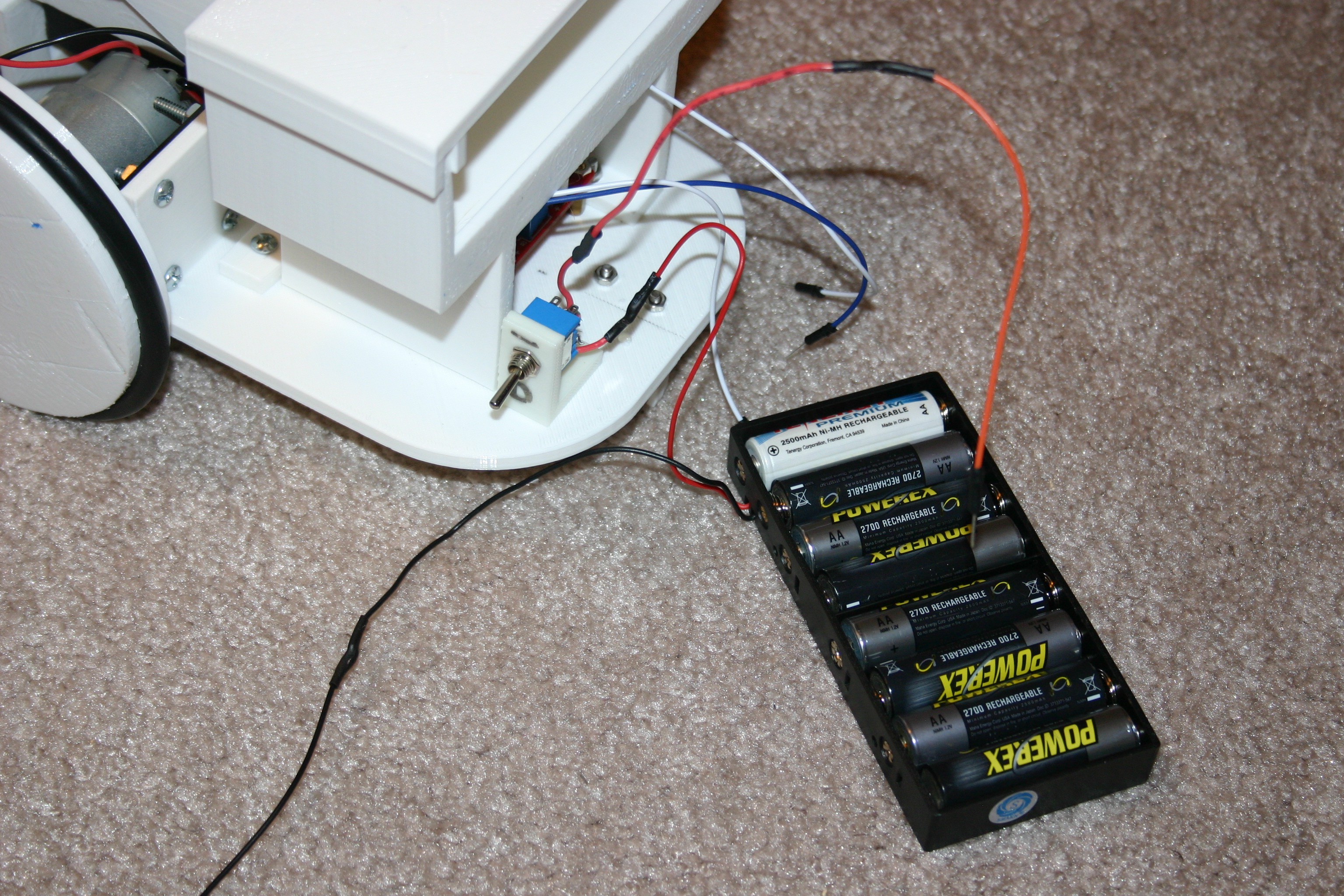
Attach the "on/off" switch into the positive power out from the battery holder. The battery holder can be easily placed into and out of the battery platform for battery changes.
![]()
Now, I can connect things on a breadboard and test as the project develops.
![]()
Pretty Useless Machine
Fling the thing with a catapult, find it, bring it back, repeat.