Close
0%
0%

Tarocco

Open Source Closed Loop Motor Controller

Similar projects worth following
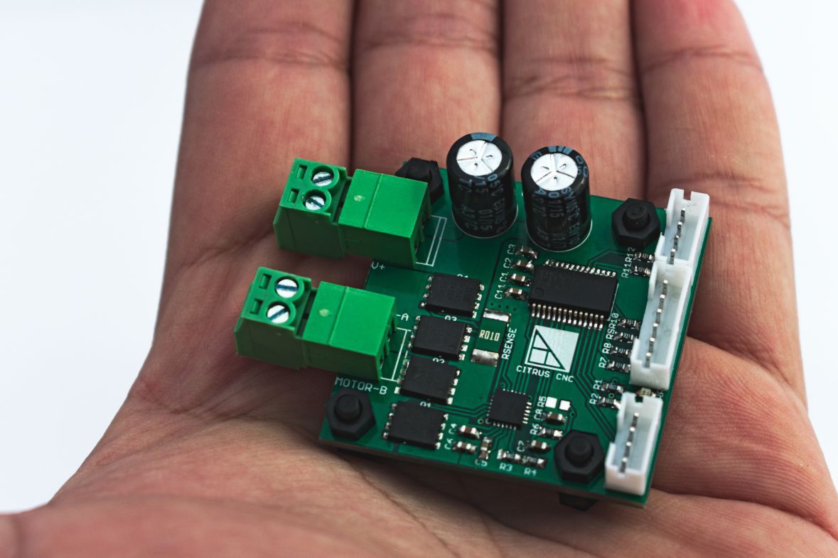
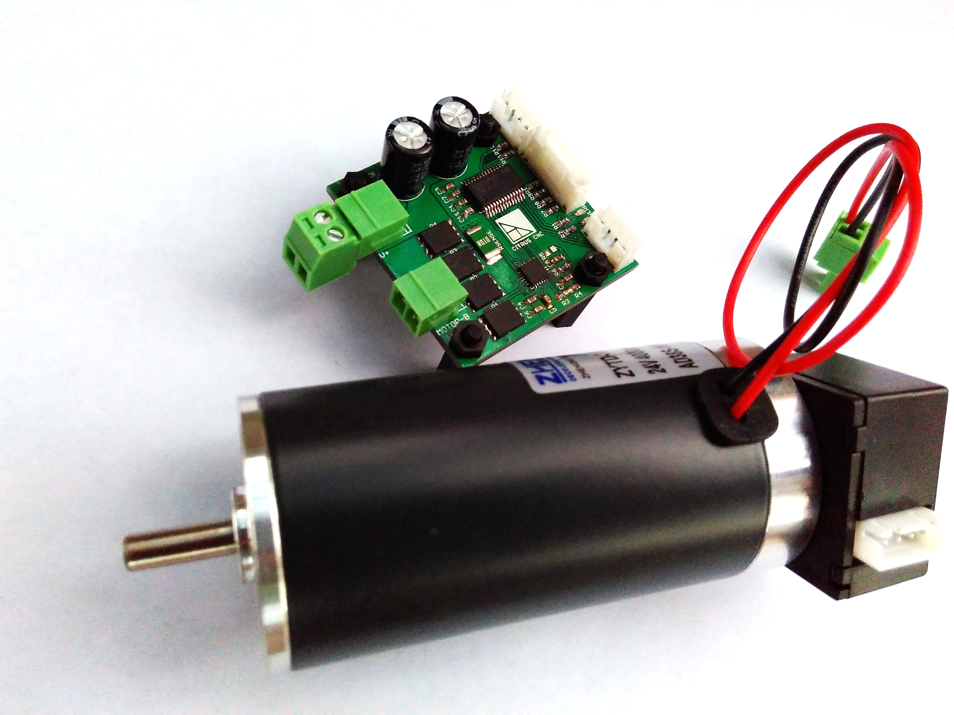
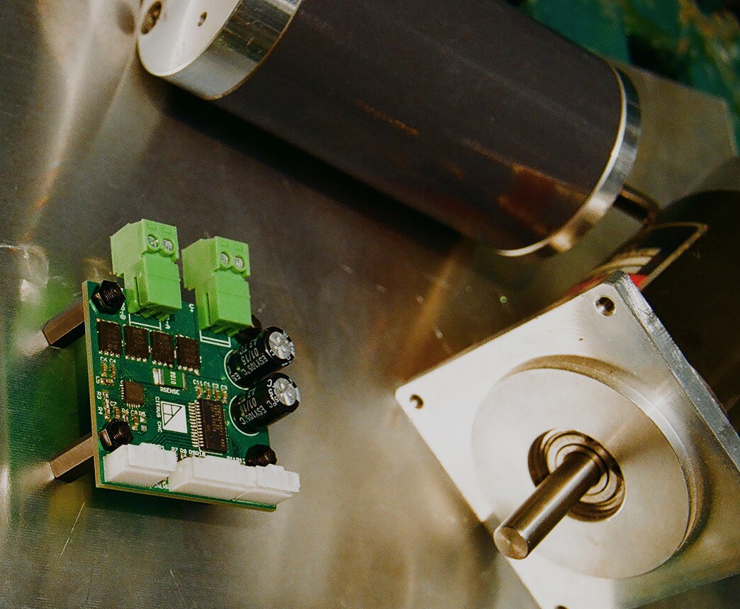
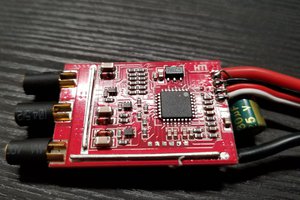
This device is designed to control DC brushed motors up to 36 V and 10 A (almost ½ hp) for axis positioning in CNC machines such as routers, milling machines, laser cutters and 3D printers.

This project is now avalilable on Crowdsupply and Tindie

https://www.crowdsupply.com/citrus-cnc/tarocco

https://www.tindie.com/products/ottoragam/tarocco/

Features

The board accepts the common STEP/DIR signals that are ubiquitous to low cost machine control boards, such as the RAMPS and parallel port breakout boards for Mach3, LinuxCNC and Machinekit.

Position sensing is achieved by means of an incremental quadrature encoder. The controller is capable of stopping the machine when it detects one of several fault conditions (discussed later) to avoid ruining a job. A full duplex serial port is available for easy configuration and tuning of the servo driver.

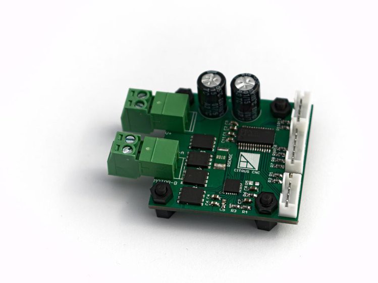
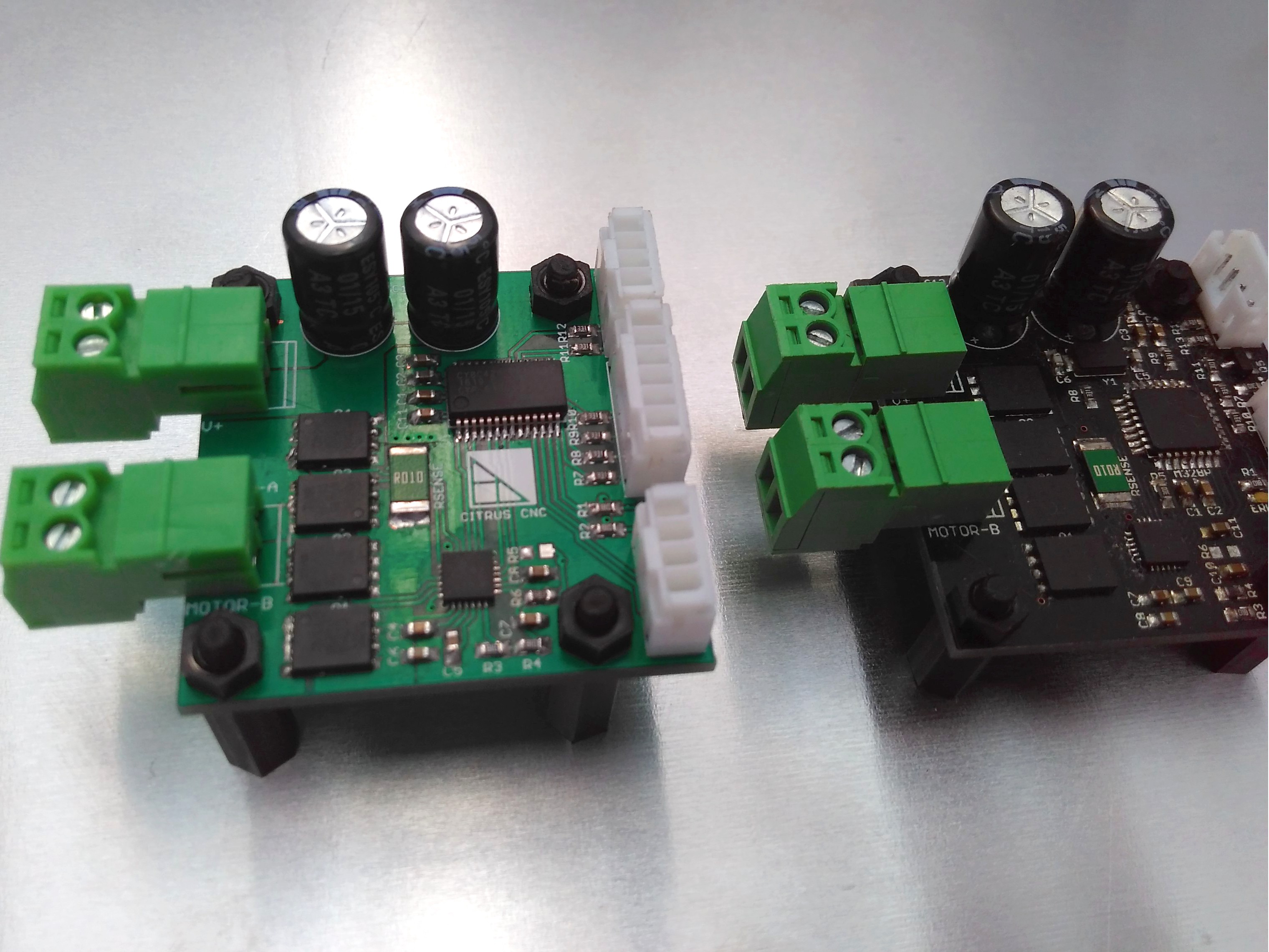
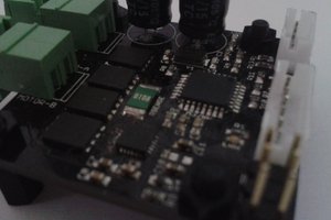
Shrouded and keyed headers for the signal connections are installed on the board to keep the end user from accidentally shorting two pins together or plugging a connector backwards. Pluggable screw terminals for the power connections allow the board to be easily installed inside a case or in tight spaces without having the cables getting in the way of the user.

SoC for Closed Loop Control

A Cypress Semiconductor PSoC4 chip (ARM Cortex M0 core plus internal programmable logic and analog hardware) is present to read the STEP/DIR signals from the machine controller, read the encoder input and perform the calculations required for closed loop control of the motor kinematics.

It controls two indicator LEDs for signaling the different fault modes the device is able to detect, such as motor overcurrent, driver undervoltage, missing encoder, exceeded encoder pulse rate and motor not able to reach position. It can also send an alarm to the rest of the motor drivers.

Gate Driver

A full bridge MOSFETgate driver switches four transistors with an appropriate voltage with the appropriatecommutation speed, while also protecting them from being damaged by a shoot-through condition oroverheating due to insufficient gate voltage or anovercurrent event.

The IC also amplifies the voltage drop from an external 5 mOhm shunt resistor for low side current sensing.

Finally, the driver also performs current chopping (set at 12 A) to provide a second layer of overcurrent protection. The current level is set via two resistors in a voltage divider configuration.

MOSFETs in H Bridge Configuration

The device utilizes four ~5 mOhm (at 25 ºC) N channel MOSFETs with a 60 V breakdown voltage. The transistors use the board as a heatsink.

Device Characteristics

Parameter

Min

Typ

Max

Unit

Motor side voltage

6


36

V

Continuous current output

0


10

A

Logic side voltage (VLOGIC)

1.8


5

V

Current consumption


50


mA

Step signal frequency

0


200

kHz

Encoder frequency (4x)

0


200

kHz

Error signal output current


4


mA

Serial port speed


19200


baud

Weight


14.5(0.5)


g(oz)

Operating ambient temperature 1

0


40

°C

1 40 ºC is the maximum ambient air temperature for which the current output value is valid

Source files: https://github.com/ottoragam/Tarocco

  • 1 × CY8c4245PVI PSoC microcontroller
  • 1 × DRV8701 gate driver
  • 1 × 0603 green LED
  • 1 × 0603 red LED
  • 4 × IRFH7545PbF MOSFET

View all 16 components

  • Tarocco on Tindie

    ottoragam08/24/2017 at 19:46 0 comments

    Just a heads up. You can now buy the controllers via Tindie


    https://www.tindie.com/products/ottoragam/tarocco/

  • The new boards

    ottoragam02/17/2017 at 04:03 0 comments

    During the past few days I was able to burn the firmware and begin testing the
    new Tarocco boards. I plan to ship half of the batch first, as soon as I'm done
    testing the boards (probably next week), so those of you who ordered the
    controller without a servomotor can begin to use them. The second half of the
    batch will likely be shipped in the following week. The servomotors should be
    ready by the second week of March.


    I've uploaded the final design files for Tarocco and the BOM tothe repo.

  • Crowdfunding campaing status update

    ottoragam01/18/2017 at 21:25 0 comments

    At just 3 days from the end of the campaign, the project is just 800 dolllars away from the goal.

    Now is the time to get your own board at https://www.crowdsupply.com/citrus-cnc/tarocco

  • Machining with Tarocco

    ottoragam12/21/2016 at 22:44 0 comments

  • Funding Campaign Started!

    ottoragam12/08/2016 at 16:49 0 comments

    The Crowdsupply funding campaign is now live! If you find the project useful please consider backing it.

    https://www.crowdsupply.com/citrus-cnc/tarocco

  • Testing the new motors

    ottoragam11/05/2016 at 15:33 0 comments

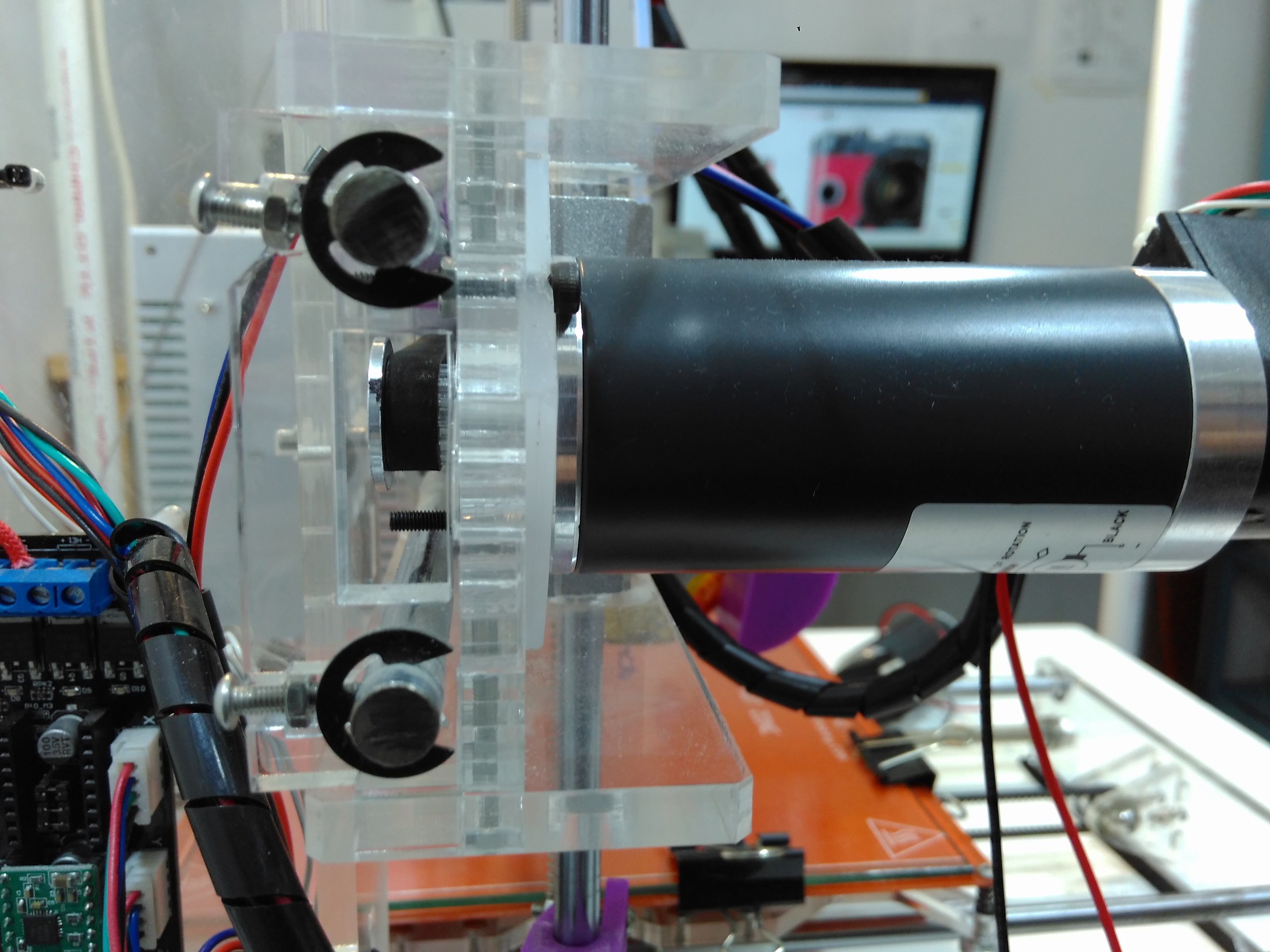
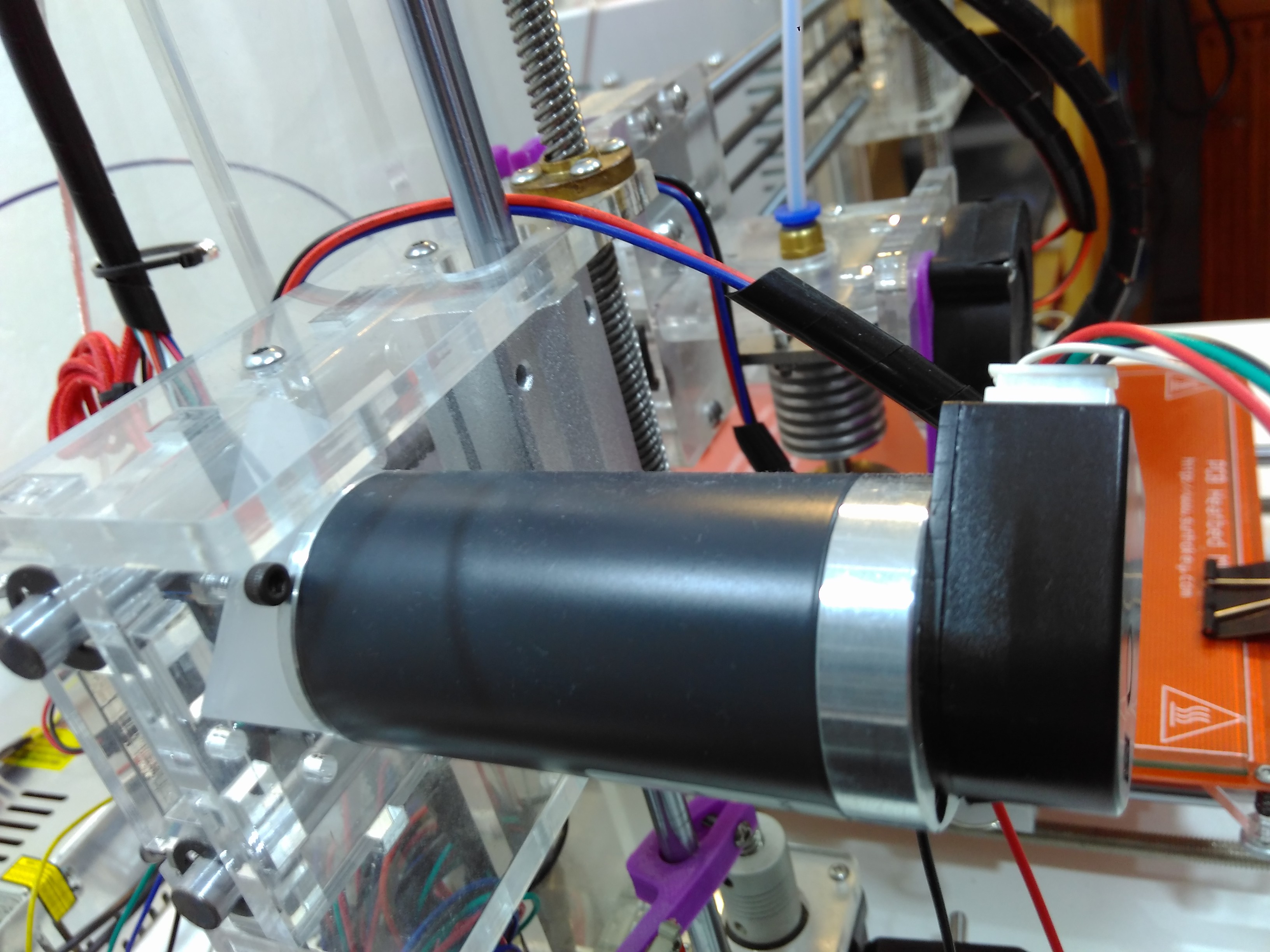
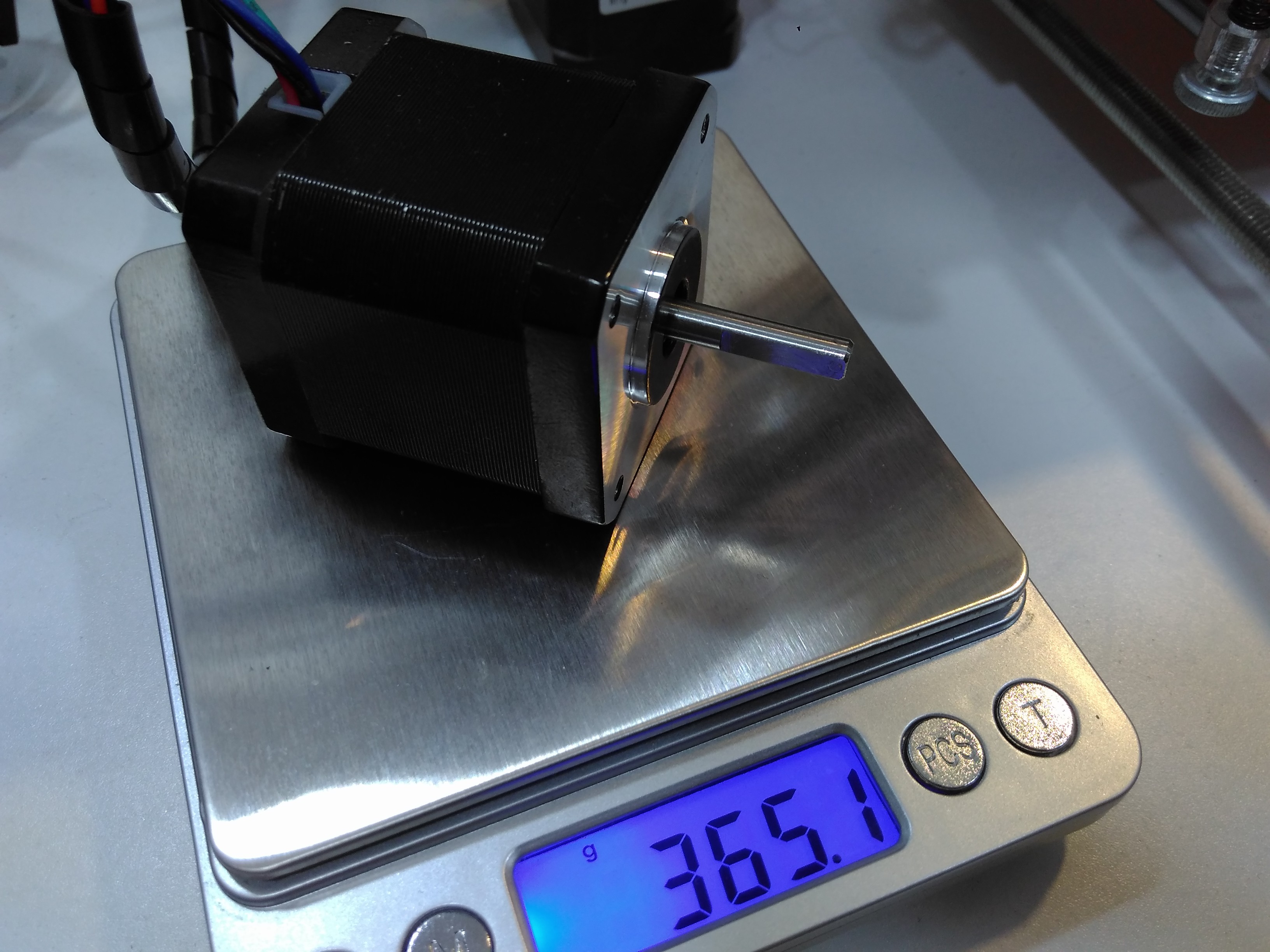
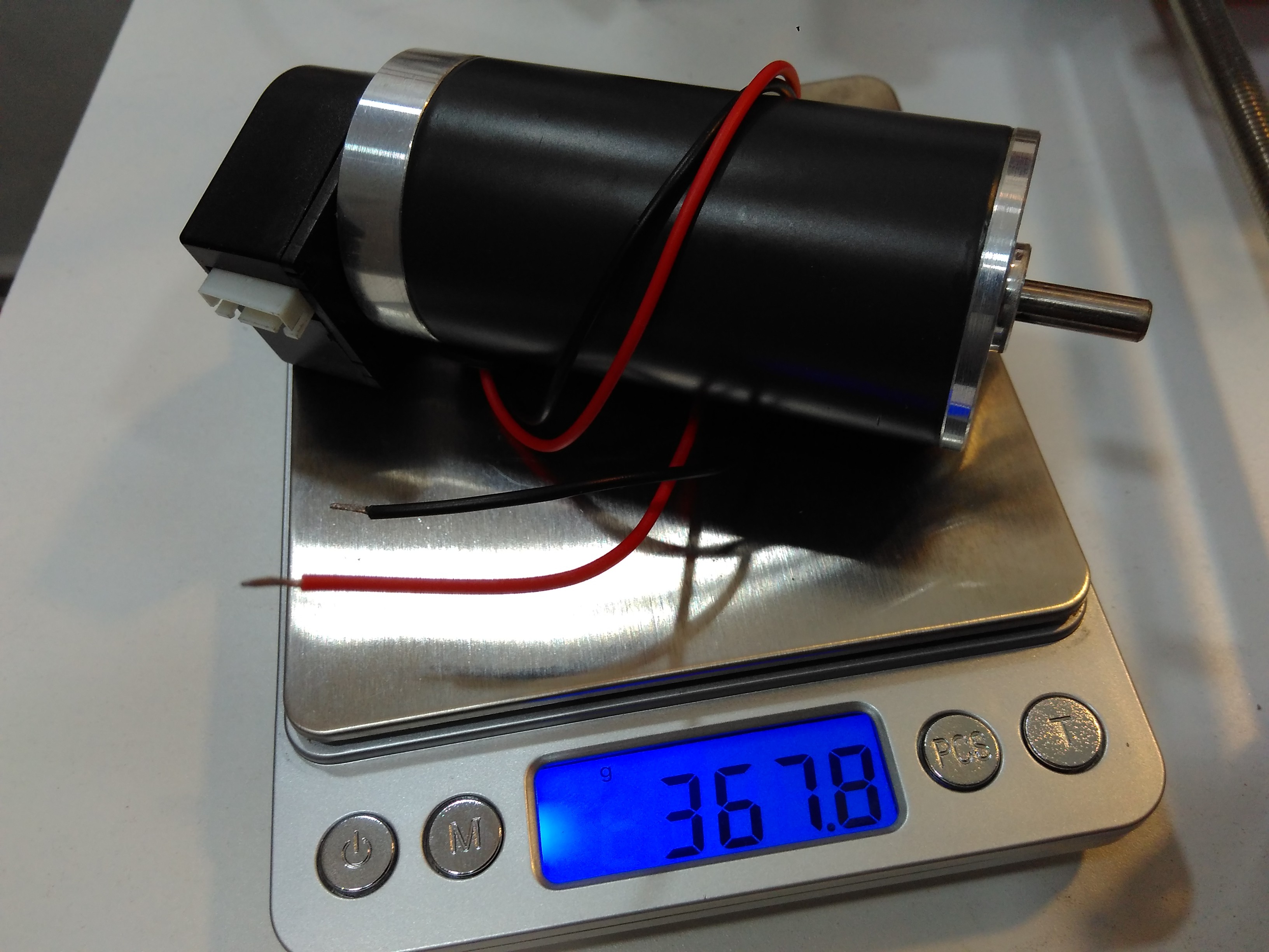
    I borrowed a Prusa i3 from a friend. I wanted to show the performance of the 30W motors I got, so I made a NEMA17 adapter from a piece of acrilyc and replaced the X axis stepper with my servomotor.

    But it has 3 times the mechanical output power!

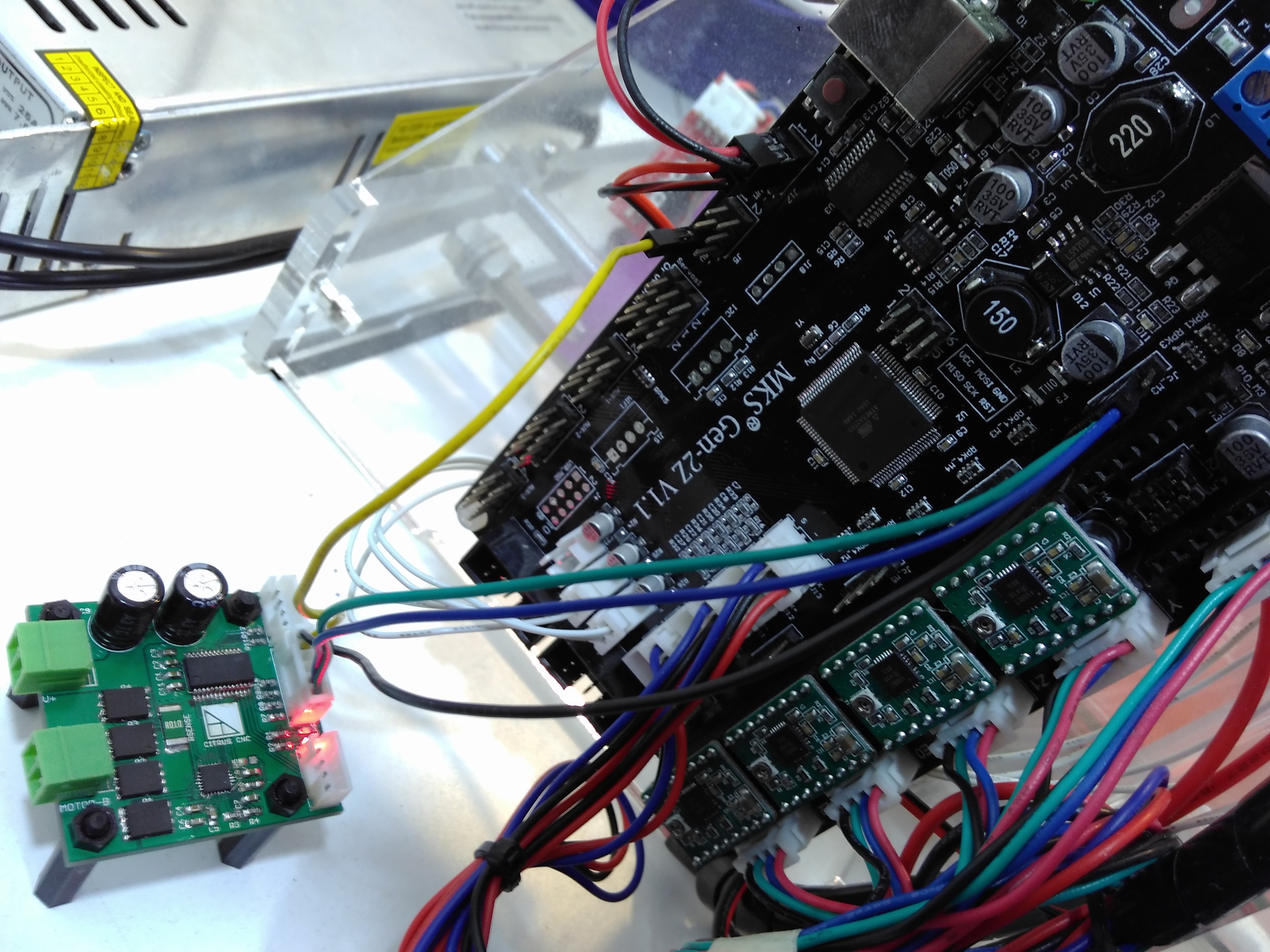
    I used one of the available headers on the MKS board to supply the signals to my controller, and removed the stepper driver from its socket.

    After getting familiar with the 3D printing software (I used Repetier), I was able to print the classic ship thingy.

    Unfortunately the printer only had space for my servomotor on the X axis, and I didn't wanted to modify it as it was not mine. The good thing is that I have an old router available for more testing. I just need to replace the steppers with the servomotors and do some testing!

  • A little update

    ottoragam10/24/2016 at 23:29 0 comments

    I'm planning to provide a suitable motor for use with Tarocco for those who don't want to go through the trouble of selecting a motor and feedback sensor.

    Last week I got some DC servomotors to test with Tarocco. They are 24V 30W units, with a maximum angular speed of 4000 rpm, and they come with a factory installer optical encoder. The encoder wheel has 360 divisions, so the encoder provides 1440 pulses per revolution.

    Physically, the motor's body is 38 mm (1.5 in) in diameter, and it has a 5 mm shaft, so it can be used to replace NEMA17 and NEMA23 motors. I'm planning to swap the steppers on an off the shelf 3D printer with brushed motors and see how the conversion goes, hopefully the frame will be able to handle the increased speed of the motors. Keep tuned for more!

  • Online project source files

    ottoragam10/14/2016 at 05:50 0 comments

    I've just begun uploading the source files to the Tarocco Github repo. If you wanted to know more about Tarocco, well, now's your chance!

  • Everything up so far

    ottoragam09/21/2016 at 13:40 0 comments

    Almost a year ago I started making my own brushed DC motor controller, after having difficulties finding a commercial unit with the right features, within my budget. As of today, I'm using the controller to successfully run a 120 pund class milling machine. However, I wasn't entirely satisfied with the first version of my controller, so I decided to improve it.

    And for anyone interested on having a ready made controller, there will be a Crwodsupply campaing launching very soon. You can sign up to get the relevant notifications here: https://www.crowdsupply.com/citrus-cnc/tarocco

View all 9 project logs

Enjoy this project?

Share

Discussions

dakota pahel-short wrote 09/24/2017 at 14:04 point

Hey, so I've been away from my extruder project because of life. I did come across this encoder: http://www.ebay.com/itm/HKT22-Optical-Rotary-Encoder-/122549225532?hash=item1c8880c83c:g:R0sAAOSwDrlZgMAc

Would it work with this system?

  Are you sure? yes | no

ottoragam wrote 09/24/2017 at 15:57 point

Hi! Yes, I think that encoder will work.

  Are you sure? yes | no

Mike Gore wrote 09/20/2017 at 17:41 point

Regarding the existing Tarocco firmware. Have you thought of adding constant velocity controll rather then just position control? ( this would require two PID functions) Examples:  Robotics frequently require velocity control with position targeting. 3D printing constant velocity helps reduce ridges when extruding materials, etc..  FYI - this all assumes of course that we would be controlling by commands not step/dir logic.

  Are you sure? yes | no

mitja.kumin wrote 08/11/2017 at 15:41 point

I'm very close to getting finished with 4 boards. I need to solder a few more capacitors and resistors. The hardest thing was sourcing the CY8c4245PVI micro controller. It's out of stock everywhere I looked. At the end I was able to order it directly from Cypress. 

For flashing the micro controller I ordered the CY8cKIT-059 from Cypress, to get the cheap version of the programmer. They ask way to much money for the MiniProg3. Now I have to figure it out how to flash the micro controller. This is my first time, dealing with this micro controller. I hope everything will go well.

It's a really nice project, still evolving and getting better and better. 

The hardest thing to solder is DRV8701; it's doable with steady hand and a fine soldering iron tip, but with a hot air station its a child's splay.

I'm really looking forward to finish the drive and getting my yaskawa minertia motors to spin.

My goal is to build these drives and motors into my CO2 laser machine.

  Are you sure? yes | no

ottoragam wrote 08/11/2017 at 19:57 point

It's very cool that you got your controllers put toghether. The stock for the TSSOP microcntroller comes and goes, indeed. I'm glad Cypress was able to help you, And yes, the 059 kit is the way to go regarding the programmer.

The QFNs can be a PITA sometimes. Even with an acceptably capable reflow oven, a few of my boards for the crowdfunding campaing  ended up with a lifted DRV8701 that I had to touch up with the hot air station.

Which version of the boards did you end up fabricating? I have both V1.0 and V1.1 files in the repo.

Please feel free to ask me anything if a problem arises :)

  Are you sure? yes | no

mitja.kumin wrote 08/11/2017 at 22:37 point

In the Github repo I was able to find only one version of gerber files, so you will have to tell me which version it is ;). I sent the files to smart prototyping in china and they made me 10 PCBs for 14$(US) including shipping cost.

I'll let you know how will thing evolve ;)

  Are you sure? yes | no

ottoragam wrote 08/11/2017 at 22:42 point

They must be the V1.0 boards then. The V1.1 design just adds fiducials for the pick and place machine and changes the programming connector for test points, so pogo pins can be used to burn the bootloader. The firmware is fully compatible between both versions.

  Are you sure? yes | no

mitja.kumin wrote 08/11/2017 at 22:52 point

Well then everything is ok. You made me a bit worried, that I'm assembling the wrong boards. Now I will have to dig into flashing the micro controller. "Problems" and questions are to be expected at this stage on. Maybe I'll have a few of them for you also ;)

  Are you sure? yes | no

ottoragam wrote 08/12/2017 at 17:43 point

Just make sure you're not use the "tarocco-proto" boards. Those were the first version of the board, way before the campaing, and lack some features of the newer revisions.

I was wrong regarding the availability of the V1.1 files on the repo. I forgot to commit, so they were not made public. I just made them available, along with a new firmware update.

And of course, bring on those questions!

  Are you sure? yes | no

mitja.kumin wrote 08/25/2017 at 17:28 point

Hello.

I was very busy lately and there was no time left to play with Tarocco. I was able to slowly finish the boards and the time for flashing came. I was able to flash the micro controller with boot loader. Regarding it was first time I did it, things went flawlessly. After flashing the PSoC Creator "said" that device was programmed successfully and the red/green LEDs started to blink Alternately. As far as I understand, this means that micro controller is in boot loader mode!?

Now I just have to wait for the USB to TTL serial converter from china and I can upload the firmware and make it a live. Or is there an alternative way to flash the board with Firmware?

I can't wait to spin up my servo motors with Tarocco ;)

  Are you sure? yes | no

ottoragam wrote 08/25/2017 at 19:03 point

Hi,

Yes, the board is now in bootloader mode. You can flash the firmware without the USB-serial converter by removing the bootloadable block from the TopDesign.cysch tab of the Tarocco project and doing a Clean and Build. That'll generate a file you can use to program the board using your PSoC programmer the same way you did with the bootloader.

  Are you sure? yes | no

mitja.kumin wrote 08/28/2017 at 19:21 point

Today I took one step ahead. I had a bit trouble understanding the manual about path to cncboot.hex and cncboot.elf files in the Dependencies tab. The manual clearly states that I should open project file in firmware folder. I went for the latest. Then I double clicked on Bootloadable_1 and then I was lost. I looked for the cncboot.hex and cncboot.elf in the firmware folder and there was no cortexM0 subfolder. Instead I should have looked in the Bootloader folder and subfolders. In the end I managed to show the right path by intuition-bootloadable probably has to do with boot loader was my thought. And I was correct. Then I took a closer look to the picture given in the manual, and there was the path going from cncboot.cydsn. 

So maybe you should write in the manual, that the path to cncboot.hex and cncboot.elf should be from the Bootloader folder and subfolders. By default on my computer was the path from Firmware folder and that was very confusing.

In the end I was able to program the board through USB to serial converter (it came today from china). The programming it self is very straight forward and I had no issues there. I was programming 4 boards one after another. Now when I connect 5V to the board it cones to life. After 3 seconds of alternate red/green LED  flashing, on 3 board red LED lights up and on 1 board green led lights up. My firs thought was, I swapped the positions of LEDs on 1 board but after checking it came out  that LEDs are on the right place. I did not connect anything else on the boards. Im suspicious that something's not OK with 1 or other 3 boards as they give different "signs of life". So my question here is, what could cause 1 board to lit green LED and other 3 red LED? Red as far as I understand shows an error and the green shows that program is running? 

  Are you sure? yes | no

ottoragam wrote 08/28/2017 at 19:38 point

True, the board programming is not as straightforward as I would have wanted, I'll take your suggestion for the manual into account.

The things that can make the ERR LED turn on are exceeding the following error limit, an external reset and a gate driver error. As you don't have the encoder connected and nothing could possibly send a reset pulse, it has to be a gate driver error. Don't worry, I experienced this too with a few of the boards I assembled, and it means the DRV8701 chip is not soldered correctly, and you'll need to reflow the IC to make it work.

I think you should continue testing the board that only has the green LED lit, and come back to the other three boards once you verify it works.

  Are you sure? yes | no

mitja.kumin wrote 08/29/2017 at 21:39 point

Today I had time to "play" a bit more with the tarok boards. I found the problem with the LEDs. Reason for not working was that I did not connect the power on the motor +/- terminals so the DRV8701 was without power. To make things confusing even further, one DRV had one pin not soldered. If I would have looked in the schematic I would have seen that I have to connect the power to the motor +/- terminals in order to make the board to function properly. 

I'm really grateful for your support and effort to help me out!

So now that everything is alive I came to the point of tuning the Tarocco for my motors. I installed RealTerm on my computer and connected the USB to serial converter. Tx from Tarocco to Rx pin on converter and Rx on Tarocco to Tx on converter. With this setup I was able to program the boards through boot loader.

Now when it comes to tuning and communicating with the Tarocco I came to a dead end. My setup is as follows: first I connected 400PPR rotary encoder to the Tarocco, then I supplied 10V to the motor +/- terminals and then I connected USB to serial converter. I connected shafts from motor and rotary encoder together, so when motor turns it spins the encoder. If I try to move the motor or encoder in this setup I hear hissing noise from the motor as it wants to remain on the current position. Green LED was lit when I supplied all the necessary power and the I moved the encoder or the motor shaft enough, the motor moved to a different position and then red and green LEDs were lit, giving a sine of error.

So then I reset the Tarocco board, only green LED was lit and opened RealTerm. I changed baud rate to 19200, chose the right com port (com7), applied the changes and I got numbers on the display. They were random like this: $000500 000300; $000500 000310; $000500 000320; $000500 000290; not necessarily in this order and this went on forever. When I moved the encoder and got the error these number change to pattern like this: $000755 000300; $000755 000310; $000755 000320; not necessarily in this order. This went on forever also. 

But I was not able to communicate with Tarocco. It could be that I don't know how to communicate, I am doing something wrong or something is wrong at hardware level. I tried to write text in the window I was getting the numbers and nothing worked. then I tried sending text to Tarocco through send tab. I wrote p5000; clicked on send text and again nothing happened.

I hope you understand what I want to say. It's a lot of things going on and I want to describe it as detailed as I can. 

I have couple of questions that come to my mind at this point:

1. How do I communicate wit Tarocco using RealTerm?

2. I probably have to define the PPR of my rotary encoder in Tarocco- where and how do I set this up?

Than you again for your support!

  Are you sure? yes | no

ottoragam wrote 08/29/2017 at 22:25 point

It sounds like your boards are working now, congratulations!

The serial data you're seeing are the error and current values (the format is "$error current;" without the ""). Try using this program https://developer.mbed.org/users/borislav/notebook/serial-port-plotter/ It'll make things easier for you. You can activate one or two axes, the first axis is the position error, and the second one is the current in mA. You can only have one serial terminal active, so you need to disconnect Realterm to use Serial Port Plotter and viceversa.

The current firmware doesn't give you confirmation for each command you send. So, for now, you won't get an answer from the board when you send it a command. You're configured it right, tho, so try sending some step pulses and see how it works.

You get an error when you exceed the default position error (255) when moving the motor by hand. If you wish to increase the threshold, you must adjust it's value by sending the coresponding serial command.

You should notice a change in stiffness in the motor everytime you update the P coefficient. It should be easy to verify it's working by sending a very low value first and trying to turn the shaft, and then sending a much higher value. It will get much more difficult to turn.

And no, the Tarocco doesn't need the encoder count data. However, your CNC software does.

I'm glad I'm able to help you, and it makes me happy that you find my project useful. I'll be here if you need more help :)

  Are you sure? yes | no

mitja.kumin wrote 09/01/2017 at 09:44 point

I learned a lot yesterday when I was playing and testing the board and communication. Firs thing I had to do is changing the motor rotation. The motor was spining the opposite way as the pulses from rottary encoder. When I fixed this the motor started to follow the position of the rottary encoder.

I was making changes to PID parameters and testing the resault by trying to manualy force the motor to move out of position. The forces necesery to do this followed the changes in PID parameters. If the force was to high I got an error from Tarroco. So things worked out.

But then I faund out, that once Tarroco goes into error, the communication with RealTerm is lost, and a reset of Tarroco is necessery to be able to modify parammeters. I faund this out the hard way. After error I tried to apply changes to PID parammeters and there was no change. It took me quite some time to figure this out. I will make more tests and reports as I get some time to play with Tarocco.

I'm not sure I understand your saing, that CNC software has to count pulses from rottary encoder. To make things easyer to understand let's asume that encoder has 100 PPR. So for one full revolution I get 100 pulses from encoder. Do I have to count these pulses with CNC software or does this mean that if I send 100 step pulses from CNC software, the motor will turn one full revolution? If the second is true than I just have to tell CNC software how many pulses do I need for the rotation of motor to move the axis of 1 mm.

  Are you sure? yes | no

ottoragam wrote 09/01/2017 at 19:16 point

When the board detects an error it will stop the motor until you reset the board, as you wouldn't want a CNC machine to keep running if the motor got stuck, that'll ruin the milling/printing/cutting job. You can keep adjusting the PID coefficients, but you won't be able to see the changes until you restart the board. What you can do to keep testing when the position error fault triggers is sending a "Clear Faults" serial command (just send e1;).

You got it right. If your encoder sends 100 pulses for each revolution, your software must send 100 pulses to complete a revolution and move the linear distance per revolution particular to your machine. That's the parameter your CNC software needs to work, how many pulses per unit of distance.

  Are you sure? yes | no

mitja.kumin wrote 09/04/2017 at 15:19 point

Ok, than all is clear ;)

I have to say I really enjoy the project, and motors are spinning to my desire. 

Is there a possible way to command Tarroco to send out current parameter values so that I can see the values and make changes? For now I have to write everything down. The list has grown very long and I'm starting to loose in all the numbers. It would be really nice to be able to se how the parameters are set. Let's say for instance, that I finish the project and is working great. But then I change some mechanical parts in the future and I need to change parameters. It's PITA to write them on the paper and save them somewhere safe inside electronics box or make a file and save it on a computer. These things get lost all the time ;).

  Are you sure? yes | no

ottoragam wrote 09/04/2017 at 18:56 point

For now there isn't a way to do that, but I'm working on a GUI that includes a plotting tool, an autotuner and a memory dump tool, so you can read the parameters from a previously programmed controller. So stay tuned :)

Do you have a picture of the boards and motors?

  Are you sure? yes | no

mitja.kumin wrote 09/04/2017 at 20:18 point

Sure I do. I tried to attach them in hire, but there is no option of doing that. Tell me where should I put them for you. If you see some value in them just grab and use them ;) I'll make a video of spinning the motor, when I find some time. 

GUI is a great way of interfacing with Tarocco. In this way all the tools you need are in one package. Auto tune is very nice feature and I believe many builders will follow because of it. PID parameters are real PITA to properly set up. You are never sure which of the three is doing a mess. It's always a guess. You change one and all collapses.

  Are you sure? yes | no

ottoragam wrote 09/04/2017 at 20:52 point

Just send them to me using the hackaday.io PMing functionality. I'll post them here if that's ok with you.

  Are you sure? yes | no

Johann Neuwirth wrote 06/18/2017 at 18:52 point

hello, thank for this great controller. I have two pieces they work with small motors fine. But I want to use bigger Motor and for that I need to push up the Ampere from 5 to 10A, but it is impossible to connect with a serialmonitor. I try to update the software with your manual and the software, but I become every time a timeout. Please can you help me.

  Are you sure? yes | no

ottoragam wrote 06/18/2017 at 19:57 point

Hi Johann! try swapping the TXD and RXD connections on the board and see if you can get the data from the serial monitor. Please let me know how it goes.

  Are you sure? yes | no

Johann Neuwirth wrote 06/18/2017 at 20:22 point

thanks for your fast answer. But try this, but I am sorry the result.

  Are you sure? yes | no

ottoragam wrote 06/18/2017 at 20:24 point

Lets see, what device are you using to connect the Tarocco to the computer?

  Are you sure? yes | no

ottoragam wrote 06/18/2017 at 23:04 point

The converter seems fine. Could you try verifying its correct operation by shorting RX and TX on the converter header and sending some serial data? It should "echo" everything you send. Also, make sure your serial terminal settings are 19200-8-N-1.

If this doesn't work, would you mind sending me a picture of the setup to see if I can figure something out?

  Are you sure? yes | no

ottoragam wrote 06/18/2017 at 23:12 point

By the way, the controller has a default current limit of 10A, so you shoulnd't need to change it. Still, that leaves us with the communication problem.

  Are you sure? yes | no

Johann Neuwirth wrote 06/19/2017 at 08:23 point

Hello, then i have some bigger problem, i cant connect via serialmonitor and not with the PSoC software. Now to the motor situation. i have two boars from the last year, i want to use dunkermotors with 24Volt and 0.98A continous current and max 9A current. and now when i connect the motor i cant turn only half turn an the controller is in the error mode. For my setup i use a UC100 CNC Controller and a standart Breakout board. i connect this with the servo driver with 5V, GND, Dir and Step. i use a 600ppr (2400 in 4x mode)  Rotation Encoder from china and a 24V Powersupply with 40A. Sorry i am not a specialist in programming, i´m only a cnc machinist with some small knowledge in electronical. sorry for my bad english. (gemoron79$gmail.com)

  Are you sure? yes | no

ottoragam wrote 06/20/2017 at 21:51 point

Apologies for the late reply. I didn't got the notification for your last comment. I'll contact you through your email account.

  Are you sure? yes | no

Solvarg wrote 06/11/2017 at 18:55 point

Hello,

Is there any chance the position through serial commands could be extended? 

Current range of + or - 255 pulses is a bit limited,  believe it's a uint8 and a uint32 would make the better sense.

Thanks

  Are you sure? yes | no

ottoragam wrote 06/11/2017 at 20:47 point

Hi! You can send a bigger value if you wish, but you'll need to increase the following error parameter value too, i. e. if you send something like 2000 pulses, the following error ust be quite a bit more than 2000 count, or else the controller will fault. The last firmware image (available on Github) supports signed 16-bit following error values.

  Are you sure? yes | no

ottoragam wrote 06/03/2017 at 02:38 point

Indeed, you should be getting 1800 positions per revolution after the reduction. The steppers are probably being used at 3200 steps per revolution, after microstepping (I'm not entirely sure). You can easily go above this value with a higher resolution encoder.

  Are you sure? yes | no

dakota pahel-short wrote 06/11/2017 at 20:36 point

gotcha. I was working on getting a higher resolution encoder. I was going with an optical one (https://www.pololu.com/product/2590) and was thinking of printing a new wheel but for some reason tarocco doesnt seen to be getting signals from the encoder. When I manually turn the wheel, nothing changes on the serial port plotter. 

However I measured the voltage coming from the A and B pins for the encoder and the voltage is responding to the movement of the wheel so everything is pinned up right as far as i can tell. Any thoughts on why the encoder movement isn't being picked up by the board?

Edit: nevermind I read this from pololu "Because the encoder board outputs are direct phototransistor outputs, some signal conditioning is often necessary between the sensor and a digital system processing the signals. For an encoder solution that can be connected directly to a microcontroller or other digital circuit, consider our magnetic encoder pair kit for micro metal gearmotors, which we generally recommend over this optical encoder."

so its not an easy fix for me i would guess. I just wish i could find higher res encoders for these little motors. 

  Are you sure? yes | no

ottoragam wrote 06/11/2017 at 20:57 point

Do you have a picture of the mechanical assembly? You could try something like this http://www.ebay.com/itm/Photoelectric-Speed-Sensor-Encoder-Coded-Disc-wheel-for-Freescale-Smart-car-D-/112030673020?hash=item1a158c687c:g:mPcAAOSwEzxYdy88. A shaft coupler is probably needed, but you can make one out of a small piece of plastic, and the encoder sensor can be directly connected to the Tarocco. You could order a custom laser cut slotted wheel and purchase an Avago HEDS-9731 (it's the one I have in my motors) or similar from an electronics distributor too. It shouldn't be more than $20 in parts, and you get precisely what you need.

  Are you sure? yes | no

dakota pahel-short wrote 05/25/2017 at 18:29 point

I'm  designing a micro extruder (30g!!!) with this board and I have a bit of a wiring question. The smoothieboard has break out pins for external drivers: step, direction, enable. Do I connect the enable to the rest pin on tarocco board?

  Are you sure? yes | no

ottoragam wrote 05/25/2017 at 20:34 point

Hi! Yes, the reset pinshould be connected to the enable pin on the smoothie. The reset is active low, so make sure the smoothieboard keeps the pin high while in operation.

  Are you sure? yes | no

dakota pahel-short wrote 05/26/2017 at 13:37 point

Btw just an update, when I tried to open Serial Port Plotter and windows prevented access saying that it was infected with Rundas.B Trojan. I'm having a little trouble finding a serial plotter that will respond to the tarocco. 

  Are you sure? yes | no

ottoragam wrote 05/26/2017 at 13:50 point

I really don't know what could be causing the antivirus to trigger. It probably is a false positive. Anyway, the serial data stream can be adjusted to send exactly the data you need in order for another program to parse it. What plotter program would you like to use?

  Are you sure? yes | no

dakota pahel-short wrote 05/26/2017 at 14:23 point

https://hackaday.io/project/5334-serialplot-realtime-plotting-software

Looks like it would work but nothing is plotting. 

  Are you sure? yes | no

ottoragam wrote 05/26/2017 at 15:08 point

I'll give that plotter a check. Write to you back in a bit.

  Are you sure? yes | no

dakota pahel-short wrote 05/26/2017 at 21:08 point

please do. figuring out how to connect to the board is a real challenge . i even turned off my security to try out Serial Port Plotter but nothing seems to be getting a response . i know the board is working. the Vin led is solid until i turn on the motor and then the fault led turns on too, but nothing seems to be allowing it to send data or receive data. 

  Are you sure? yes | no

ottoragam wrote 05/26/2017 at 21:42 point

Try inverting the connections of the motor to avoid the fault when you try to spin it. Yo can use any other serial terminal program in the meanwhile, like realterm. You should see the numeric values that the Tarocco reports in the terminal window. If not, then the problem is probably caused by something else.

  Are you sure? yes | no

dakota pahel-short wrote 05/26/2017 at 21:55 point

I tried realterm. Nothing is giving me feedback. 

  Are you sure? yes | no

ottoragam wrote 05/26/2017 at 21:56 point

Try inverting the RXD/TXD connections, that may do the trick.

  Are you sure? yes | no

dakota pahel-short wrote 05/26/2017 at 22:14 point

Well that did something! I now see E0 on the screen over and over again in realterm. I also inverted the motor but it still faulted when the enable pin activated. 

edit: for some reason it rest the baud rate while i wasnt looking. changed it back and im getting $numbers which seems more correct. 

  Are you sure? yes | no

dakota pahel-short wrote 05/26/2017 at 23:05 point

So feedback is definitely happening but nothing seems to be improving the motor position. I told it to extruder 5mm and it will go from $000503 000310 to $002803 000310 and no inputs to the p seems to affect it. though it also is showing a fault right away even though it says $000500 at the start which should be no positional error. it is not the motor connections because i tried reversing those. 

  Are you sure? yes | no

ottoragam wrote 05/26/2017 at 23:56 point

It seems that inverting the motor wires is causing it to runaway. You can invert them again, or send the "invert direction of rotation command". Also, Serial Port Plotter will probably work now.

  Are you sure? yes | no

dakota pahel-short wrote 05/27/2017 at 02:08 point

I wish it was that. I've flipped it back and forth several times and nothing has happened. Everything seems wired right though. It's fun to manually move the encoder and see the number change. I'm gonna update the firmware and test that in a few days (i just got commissioned for a few hundred dollar print... gotta get the old extruder working again XD) 

So about serial port plotter, how do you use it to send commands to the driver? I didn't see anything about that in the interface. Though i did only use it for a few minutes before i turned the windows defenses back on and it removed the program....

  Are you sure? yes | no

ottoragam wrote 05/27/2017 at 02:48 point

For now I'm usign realterm to send the tunning commands and serial port plotter to visualize the error during motion. I plan to release a custom terminal program to configure the various firmware parameters and visualize the plot all in one, and later add a PID autotuner option using the controller data.

  Are you sure? yes | no

dakota pahel-short wrote 05/27/2017 at 03:08 point

that sounds awesome. i really wish i knew more about coding so i could help. i had actually wanted to set up an autotuning for this project but time is a factor im short on and i'm only half as computer smart as id like to be. 

how are you using the two programs together? it seemed like only one program could access the serial port at a time when i was doing tests. 

  Are you sure? yes | no

ottoragam wrote 05/27/2017 at 02:49 point

I forgot to ask, how are you maing the motor move? If you're using the +/- command that could cause the motor to suddenly jump due to the large change in error and thus signal a fault. I recommend that you use the step signal to test the controller.

  Are you sure? yes | no

dakota pahel-short wrote 05/27/2017 at 03:01 point

because it is attached to the extruder, i've been using the "extruder 5mm" that's a default setting from the lcd screen. however it also seems to fault everytime the motors are enabled.

  Are you sure? yes | no

ottoragam wrote 05/27/2017 at 03:23 point

I can't use both programs at the same time, I need to jump between them. That's why I need to get my own terminal ready, as it would make configuring the board much easier.

  Are you sure? yes | no

dakota pahel-short wrote 05/31/2017 at 16:45 point

Okay so I finished a large commission for someone and back on the project. I have come to the conclusion that the reset pin being attached to the enable pin was the issue. 

For anyone else interested, the smoothie board has the enable pin activate the motor drivers on "low" but it can easily be inverted to "high" in firmware by adding a "!". However, because the reset pin does not actually reset the board and instead produces a fault, connecting the enable pin to the reset will always produce a fault because the motors start off (low if inverted) and are only turned on at first homing or movement. 

I'll test it now with reset connected to error pin like the manual suggests and see how that goes. 

  Are you sure? yes | no

ottoragam wrote 05/31/2017 at 19:46 point

Let me know if everuthing goes as expected :)

  Are you sure? yes | no

dakota pahel-short wrote 06/01/2017 at 02:00 point

Its working. A bit of a pain to tune but it'll be extruding plastic in a day or two I'm sure. Any suggestions for settings or the tuning process? I'm shooting in the dark and so far my graph looks like an earth quake lol. 

  Are you sure? yes | no

ottoragam wrote 06/01/2017 at 02:05 point

Don't mess with the integral and derivative errors until the proportional coefficient gets you close to an acceptable performance. Then, the integral coefficient is useful to get things close to 0 encoder counts of error and make response faster. You may even leave the derivative coefficient at 0. You can try the Ziegler Nichols tuning method too.

  Are you sure? yes | no

dakota pahel-short wrote 06/01/2017 at 17:57 point

Thanks that helped I got the first print test:

and a question for you. I screenshot my serial port plotter. I think I need to slow down retractions because its producing variation but the best I can seem to go is get the extruder to be within +/- 5 steps. Is what I'm showing pretty normal?

https://imgur.com/a/mh4n8

  Are you sure? yes | no

ottoragam wrote 06/01/2017 at 18:47 point

Everything seems normal, and I think you're right, the error during the retraction could probably be taken care of by making it slower. Maybe the behaviour you're seeing is not even caused by the PID settings, but the motor. If it isn't mechanically capable of reaching the acceleration you want, no amount of tuning will fix it. You could try getting more torque (more acceleration) out of it by increasing the voltage, or lowering the inertia of the mechanism.

The second graph looks good! You can make the error even less by using a higher resolution encoder. What resolution are you using now? Feed rate?

  Are you sure? yes | no

dakota pahel-short wrote 06/01/2017 at 19:02 point

its a 1:150 gear reduction micro dc motor with an encoder that measures 12 points every rotation. I'd love to get an encoder with better resolution. I just havent seen any for these micro dc motors. 

its a 40 oz in motor so it should have plenty of torque for extruding. the motor is rated for 12v but ill see what happens if i attach it to my 24v power supply. 

  Are you sure? yes | no

ottoragam wrote 06/01/2017 at 18:53 point

You probably know this, but increasing the voltage of the motor supply will make the motor capable of reaching a higher maximum speed and there will be more current through it (wich causes the torque increase). Make sure the motor can handle the extra heat!

  Are you sure? yes | no

ottoragam wrote 06/01/2017 at 19:44 point

The encoder resolution has room for improvement. You could get a optical codewheel and a photodetector/emitter to make your own encoder. The codewheel is very thin and light, so you could fit it through the front shaft of the motor (3mm, right?)

It sounds like the torque is sufficient. increasing the voltage is most likely not worth the risk of frying the little motor

  Are you sure? yes | no

dakota pahel-short wrote 06/02/2017 at 18:06 point

Just wanted to double check something. The tarocco driver uses the encoder counts to do steps per mm right? So my motor with a gear reduction of 1:150 and 12 point encoder should have 1800 points per revolution right? Because right now the extruder has a really low steps per mm. its at 90 steps per mm which is at least half of what I am use to with a stepper motor that has only 200 steps per rotation. 

  Are you sure? yes | no

Rost wrote 05/14/2017 at 22:56 point

Hi! How it's going Ottoragam?) Any news about your video tutorial for motor tuning from PC ?

P.S. Still have my interest to your project. )

  Are you sure? yes | no

ottoragam wrote 05/14/2017 at 23:54 point

Hi Rost! I've been really busy improving the firmware and dealing with the assembly of the next board batch. I believe I'll be able to work on some other things, like the guide, next month.

  Are you sure? yes | no

Rost wrote 05/15/2017 at 11:15 point

I see. Will be waiting for it. Good luck with your work. ) 

By the way. New firmware will be availible to download?

  Are you sure? yes | no

ottoragam wrote 05/15/2017 at 17:43 point

Of course. Everything will be made available via Github :)

  Are you sure? yes | no

Rost wrote 01/28/2017 at 21:41 point

Hellow again. I have another question. Will it work with 48 volts power supply normaly? If not, what changes shold be done to the board to accept such voltage?

  Are you sure? yes | no

ottoragam wrote 01/29/2017 at 09:49 point

I don't think it would be possible to work at such voltage. I think the maximum should be 40 V. The gate driver (practically the heart of this design) is rated for 45 V and a maximum of 47 V. You could probably run your motors at a lower voltage without loosing too much.

  Are you sure? yes | no

Rost wrote 01/29/2017 at 12:17 point

I see, thank you. You told me that it is easy to control the driver using usb-uart converter with serial terminal like Realterm. I made a search for example how to do that on youtube and thound nothing usefull. Will you make instructions video on your youtube channel in the future showing how to do that?

  Are you sure? yes | no

ottoragam wrote 01/29/2017 at 13:35 point

Yup, I plan to make a video tutorial for the board. I recommend you read this https://www.crowdsupply.com/citrus-cnc/tarocco/updates/quick-start-guide
It should give you a basic idea on how the board is used.

  Are you sure? yes | no

Rost wrote 01/29/2017 at 15:58 point

Thank you. Will wait for it. You said in the guide about encoder errors depending on motor speed. On what speed it starts to happen? i am going to use 1600 rpm motors and 600 ppr encoders. As I can understand errors problem is about much higher speeds and high resolution encoders. Do I understand it right?

  Are you sure? yes | no

ottoragam wrote 01/30/2017 at 04:32 point

The speed at wich the error becomes more significant depends on the motor, the tuning and the thing it is coupled to, I cannot say how much the error will be. Don't worry too much about it tho, many times the error will be below the mechanical tolerances of your machine components, and you could do a finishing passes at low speed when you need to be more accurate.

  Are you sure? yes | no

Rost wrote 01/24/2017 at 17:05 point

I have more questions. Will you provide print layouts for the board, instructions for controller flashing and capasitors and resistors used? I am not experineced in electronics so any manuals and information will be very helpfull.

  Are you sure? yes | no

ottoragam wrote 01/25/2017 at 23:55 point

Hi Rost! Sorry for the delay, I was a bit busy. The design files and the manual are hosted on Github.

To connect the board to a pc you'll need a USB-serial converter, like the popular FTDI boards. Then you can use a serial terminal program like Realterm to monitor and adjust the parameters for operation. You can use any microcontroller to command the controller to move the motor, just send it some high-low pulses.

  Are you sure? yes | no

Rost wrote 01/26/2017 at 00:25 point

Thank you for answer. I took a look on a board schemе but i noticed it has some polygones and i need to learn how to make it printable for a laser printer mask, because all my experience was just a few boards made long time ago in an old style way.) I wiil try to learn how to make the board scheme printable or i can relay on your recomandation. Maybe you know a good youtube links how to make boards print close to the type of yours. I anderstand my questions are very beginner level, so thank you for your patience.

  Are you sure? yes | no

ottoragam wrote 01/27/2017 at 10:38 point

No worries :) You need to click the Ratsnest button first to fill the polygons. Then activate the pads, vias and top (and then bottom) layers to see only the copper zones on the board. Then go to file-print and check the mirror and black options before you print the mask.

  Are you sure? yes | no

Rost wrote 01/27/2017 at 19:58 point

Thank you. I tried and now it's allmost clear. Next step to order materials and components. Some of them long time to wait. But it's a good hobby time for winter.)

  Are you sure? yes | no

Rost wrote 01/24/2017 at 14:43 point

Hi! Can you recommend simple setup ? I want to make one driver board only and connect it to pc via usb for example. What simple soft i can use just to check dc servo for steps and rotaition besides arduino and grbl?

  Are you sure? yes | no

mitja.kumin wrote 11/24/2016 at 22:33 point

Interesting project! Just what I need to upgrade my CO2 laser stepper motor system. Is there a way to setup the PID parameters and how it is done?

  Are you sure? yes | no

ottoragam wrote 11/24/2016 at 23:31 point

Hi Mitja, I'm glad you like the project! The controller settings, including the PID coefficients can be modified via serial commands. You just need to send a packet like p234; to modify the non volatile values for each parameter. The controller also transmits back the errror value in real time (100 Hz), to make the calibration process easier.

  Are you sure? yes | no

ottoragam wrote 11/24/2016 at 23:37 point

I plan to upload a video of the whole process soon. Give me a day or two and it will be ready :)

  Are you sure? yes | no

mitja.kumin wrote 11/25/2016 at 18:19 point

Fantastic! I will make PCBs this weekend. I will make some tests with yaskawa DC servo motors. My plan is to use these in my machine. I also have some BLDC servo motors, some of them quite massive but they will have to wait for another kind of controller.

About rotary encoder: if math serves me well I can use 600P/R encoder. That would result in 40kHz at 1000RPM. So the encoder frequency would max out (200kHz) at 5000RPM which is way to high for even a 5mm pitch lead screw. This would result in speed of 25m/min. My goal is resolution and with 600P/R encoder i get insane resolution of 2um. In reality this is impossible to achieve on home built machine. 

I will probably go with 400P/R encoder, as this gives me a resolution of 0,02mm with GT2 timing belt (2mm pitch and 16 teeth pulley) and the encoder frequency will max out at 7500RPM which is 15m/min. But that won't happen because motors don't spin so fast.

Instructional video of controller setup would be really great addition and will make the project even come closer to the end user.

  Are you sure? yes | no

ottoragam wrote 11/25/2016 at 20:16 point

Your calculations are correct :) Do you have more info on those servos of yours? I also have the BLDC version of this controller, the hardware works, but I have not done any firmware development beyond a basic commutation test. https://goo.gl/photos/ez6WvvWxp35TmKAA7

I plan to use it on a RF45ish mill build. If you want I can upload the hardware files, but I don't think I'll make any software progress till I complete the Tarocco project.

  Are you sure? yes | no

ottoragam wrote 11/25/2016 at 20:21 point

I also uploaded a user's manual. It is not complete yet, but I think it could be useful. Check the project files section

  Are you sure? yes | no

mitja.kumin wrote 11/29/2016 at 20:28 point

Great I will take a look tonight.

About the servo motors: I have 3 pcs yaskawa minertia motor, model T03M-AR21. I got lucky and got them on MAM Radio Messe in Friedercshafen for 10€/piece. They are not specifically strong but as they can turn faster than steppers I can implement reduction pulley to reduce turning speed and increase torque. 

I really hope you will work on BLDC controller in future. I have projects to use the motors but no controller. The only difficulty could it be that they need higher voltages, like 90V and even 110V. I regularly go on fairs in Italy and Germany to find used industrial ware for small money. The servos are usually without drives :(

  Are you sure? yes | no

mitja.kumin wrote 11/29/2016 at 20:59 point

I read your manual and I have to say that some things are much clearer now. I really appreciate your effort. Writing a manual is a hard task and it takes as much time writing it as it takes for the project development. But in the end there are always few users more because with manual all is explained and immediately known what can be expected prom the project. 

About the design: is this final or will there be some upgrades in the future? 

I have on my mind opto isolation of the inputs/outputs, some way of mounting a heatsink on the transistors if needed (those glue on type sucks).

  Are you sure? yes | no

ottoragam wrote 11/29/2016 at 21:54 point

 That's a amaaazing price for the motors! The only change I have in mind for the controller is moving the step and direction pins to port 0, as port 4 pins cannot connect to the internal programmmable logic of the PSoC. That would allow the controller to potentially handle step pulse frequencies above a MHz, tough I doubt it would be that useful many of us. The other advantage would be the option of decoding a wide variety of signals in hardware, not just only step and direction.

I tought that a good way to heatsink the transistors would be with something like a laser cut 3mm Al sheet that can be installed using the pcb mounting holes. You could even put a 40 mm fan on top.

I use a beaglebone with machinekit to control my machines. As you can see, the optocouplers are on the connector cape. I feel it is more versatile this way, as people who don't need isolation can save a bit of money.

I've tested these boards with H11L1 optoisolators, they're fast, work fine and are not expensive.

The BLDC controller should be able to handle motors up to 150V with the correct FETs and capacitors. I think a good value would be 90V, as higher voltage components start to get kinda expensive from here. Cheap quick switching, low resistance MOSFETS are very rare past ~120 V, in my experience. I am using 75V FETS as of now, cause I only need 48V for my motors, but I think it would be a good idea to change them. There are not many "high voltage" economic controllers out there, as you point out. I'll try to post the BLDC controller files on this site as soon as I can.

And please feel free to ask about anything that's not covered in the manual :)

  Are you sure? yes | no

psykhon wrote 10/27/2016 at 16:17 point

Could you also provide/recomend a more powerfull motor?

  Are you sure? yes | no

ottoragam wrote 10/27/2016 at 20:24 point

Hi psykhon! Would http://www.robotmarketplace.com/products/0-M27-150-P.html be of use? It is a ~120W unit.  Can you tell me more about your motor requirements? price point? I should be able to supply some other motors, based on the needs of the project followers.

  Are you sure? yes | no

Rainer wrote 10/21/2016 at 11:02 point

Will the new controller board also be open-source/open-hardware like the first one or just closed-source and available to buy from you or crowdsupply?

  Are you sure? yes | no

ottoragam wrote 10/21/2016 at 11:11 point

Hi Rainer! You can check most of the design files for this project here: https://github.com/ottoragam/Tarocco

Right now there are some minor features missing, and I still need to add the BOM. But you're welcome to ask me anything about the new design (the main change is the microcontroller, Tarocco uses a CY8C4245PVI instead of the Atmega328)

  Are you sure? yes | no

Rainer wrote 10/21/2016 at 11:18 point

Thanks for the github link. :)
I think of replacing my steppers on my little desktop cnc for brushless motors. So i'm quite interested in such a controller which also is affordable. All industrial brushless controller are way to expensive for me.

  Are you sure? yes | no

ottoragam wrote 10/21/2016 at 11:36 point

Yup, I faced the same pricing issue, that's why I decided to make this
thing. Have you chosen the motor yet? Maybe I can convince you to use
some affordable brushed servomotors instead? I plan to provide a full kit for those who have trouble sourcing the motor. It is a 24V 30W motor with a maximum speed of 4000 rpm, with a 1440 pulses per revolution optical encoder.

  Are you sure? yes | no

Similar Projects

Does this project spark your interest?

Become a member to follow this project and never miss any updates