Alex
Alex-
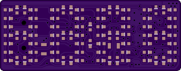
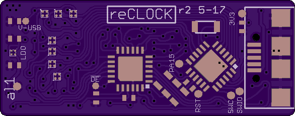
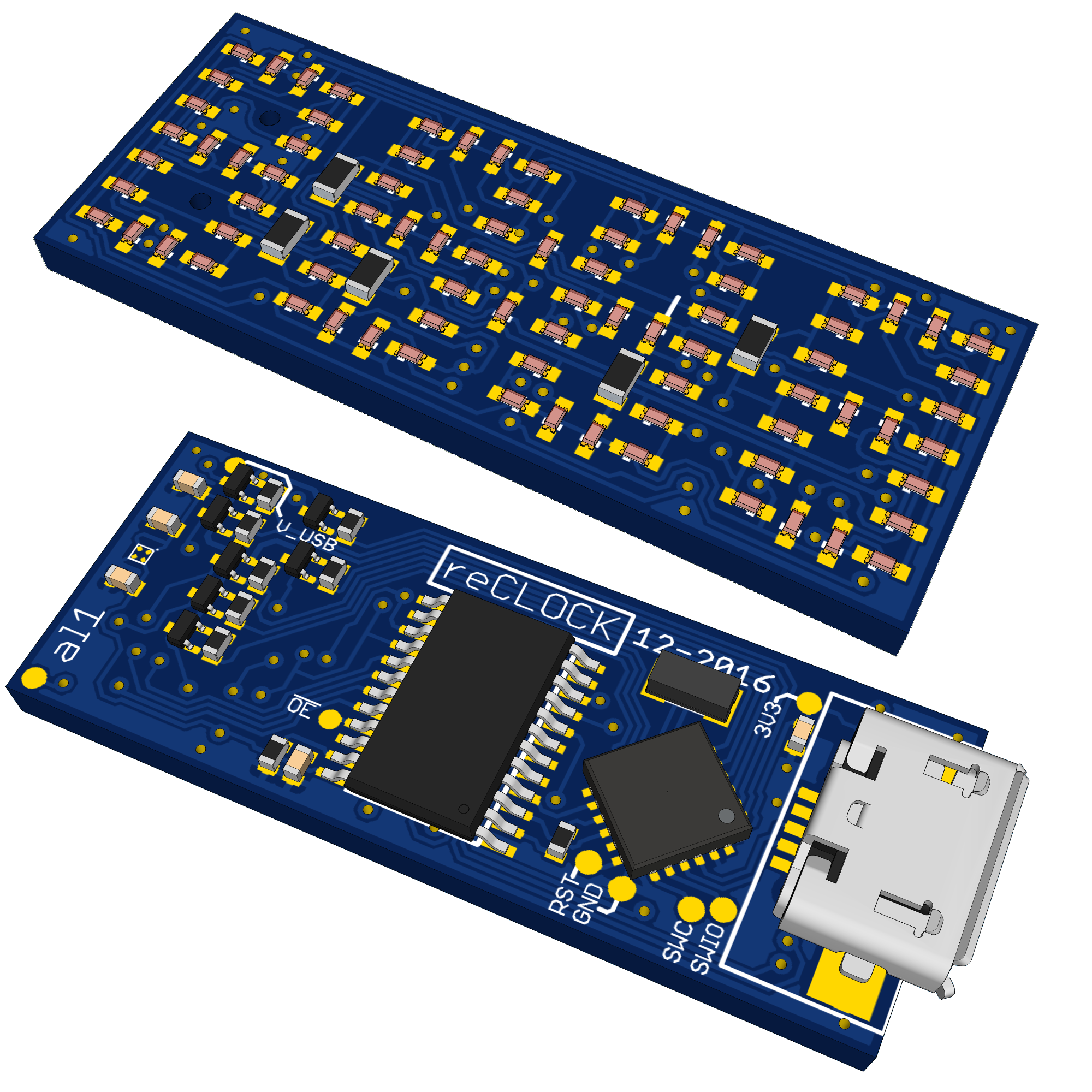
rev2 - now with more BGAs
05/08/2017 at 21:08 • 0 commentsAlso the first PCB, did worked. There are some issue:
- It could only run on 3.3V because of a mistake with the p-fets
- The footprint of the LEDS were so much undersized, that soldering was quite difficult an unreliable
- The TSSOP package of the shift register looks to big
As Solution a made a new revision:
- Now with smart integrated high-side switches (TPS22912 or similar) and because of these with more BGA parts
- Bigger Solder pads for LEDs. Some new routing was needed, because now only one trace fits under each LED. But OSH-Park's new 10mil Drills helps a lot.
- the shift register is now also QFN.
Here some preview of the boards:
![https://644db4de3505c40a0444-327723bce298e3ff5813fb42baeefbaa.ssl.cf1.rackcdn.com/0a4dee0b8100185b6cf9e72fe5e1ab41.png]()
![https://644db4de3505c40a0444-327723bce298e3ff5813fb42baeefbaa.ssl.cf1.rackcdn.com/e75af9613ec6411b1cc002d919543d40.png]()
-
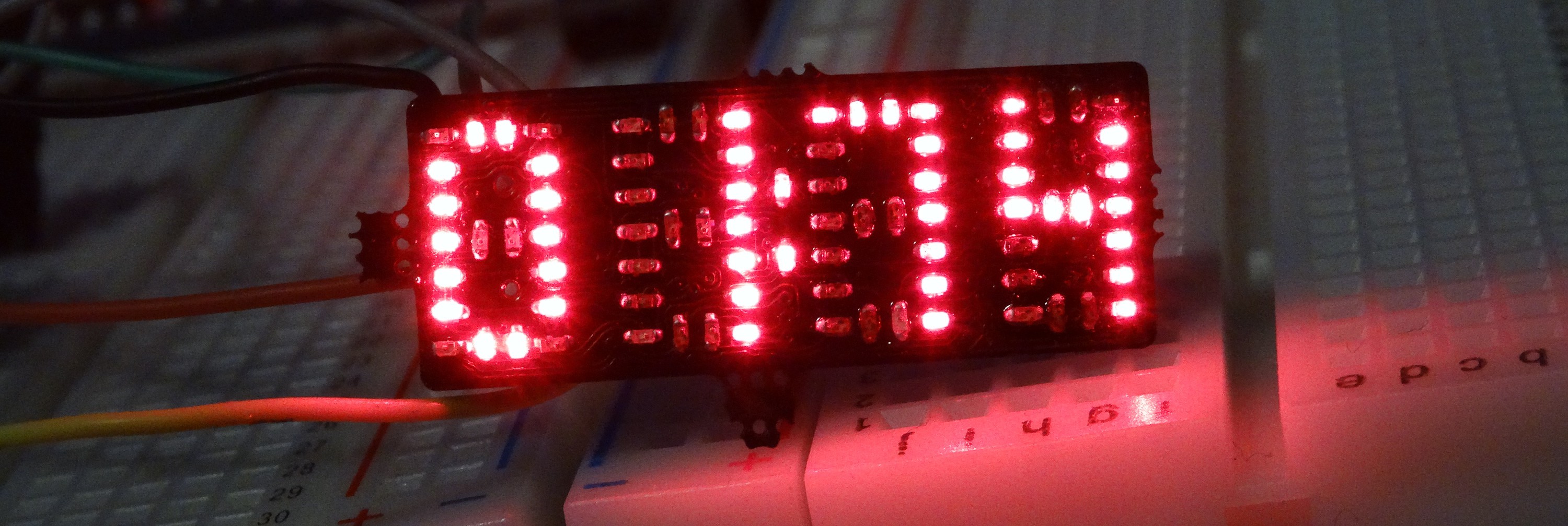
now with all for digits
03/31/2017 at 21:02 • 2 commentsall soldering done
![]()
-
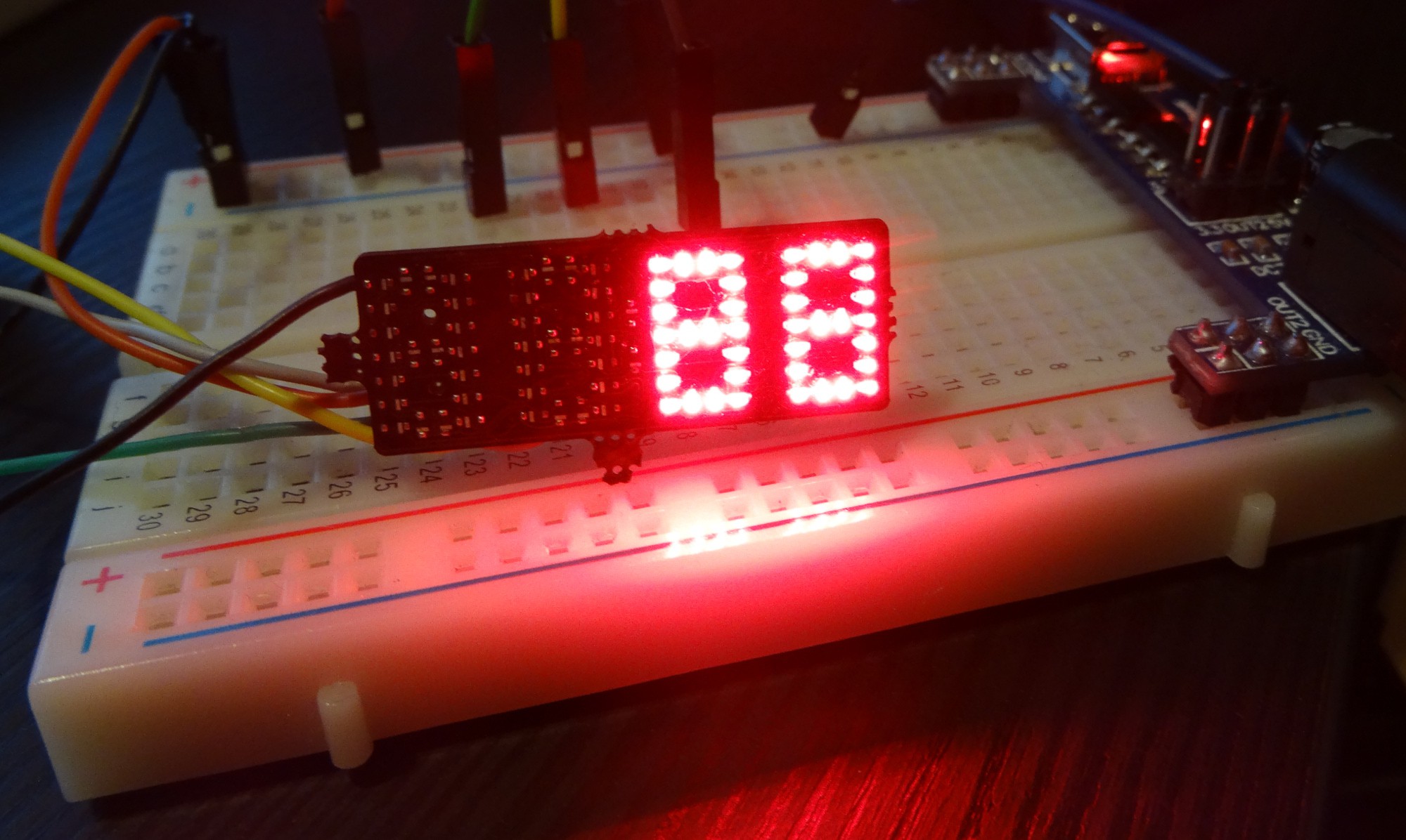
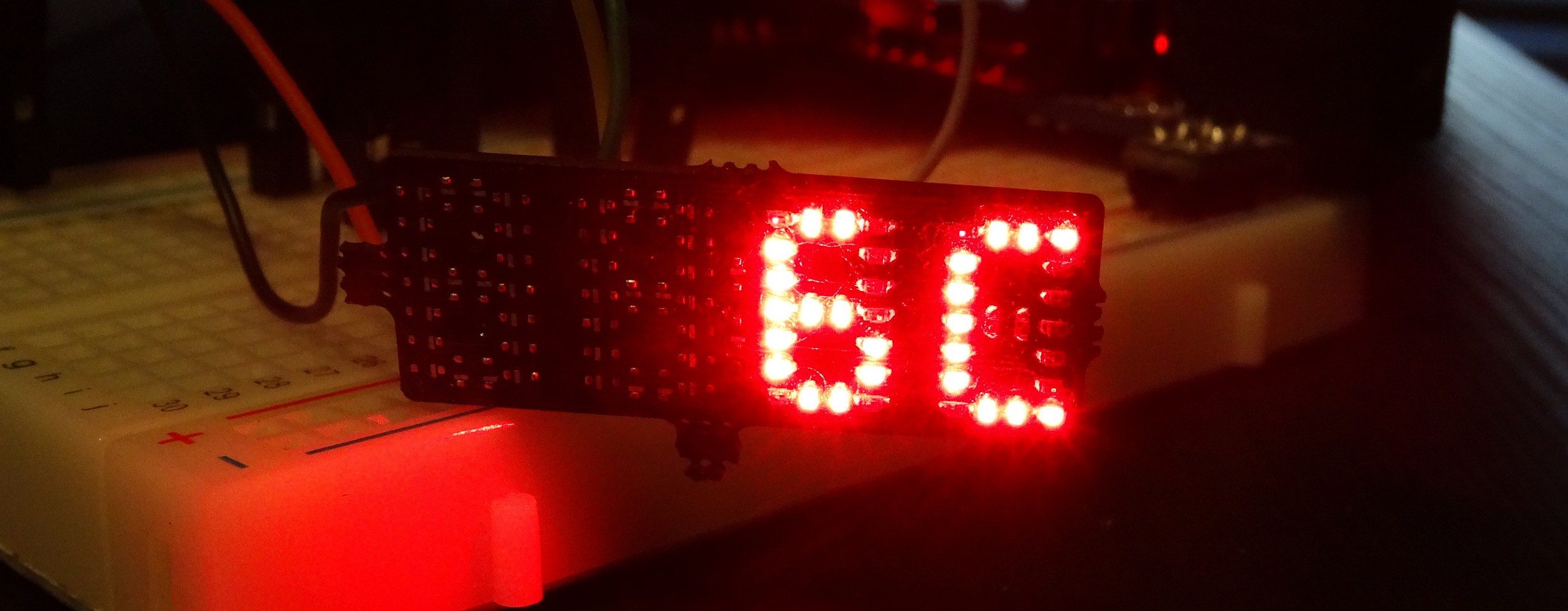
two digits soldered and working
03/29/2017 at 18:45 • 1 commentit is partial working!
![]()
![]()
-
update
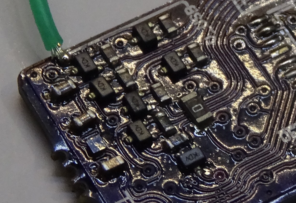
03/29/2017 at 16:28 • 0 commentsThis project is still ongoing and I did received the PCBs some time ago. I also started soldering and programming. Here a picture of the line driver section of the PCB:
![]()
I also got a little bit into trouble with the LEDs. Some how I placed them all in the wrong direction in the schematic. So that the cathode marking on the PCB is now an Anode marking. The really bad thing is that I noticed that after soldering all LEDs the wrong way around.
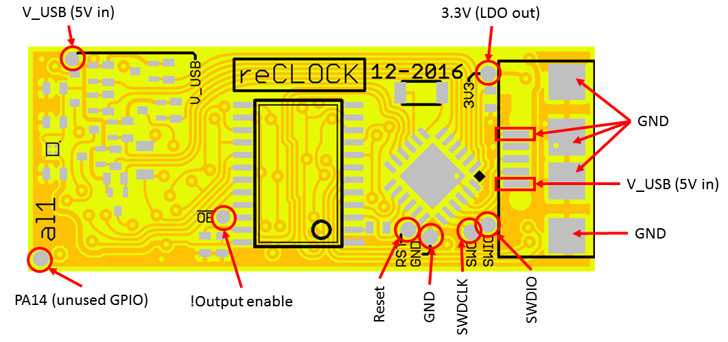
During the first programming/debugging secessions I also made this test pad overview:
![]()
-
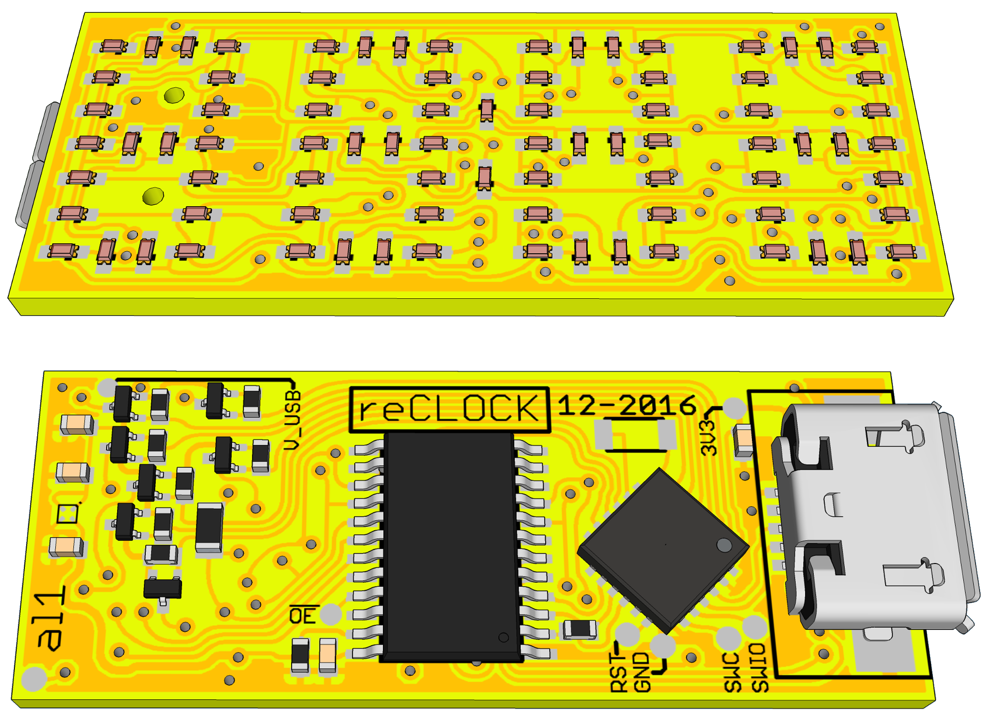
PCBs rev1
01/12/2017 at 18:01 • 0 commentsThe PCB design is ready. And there are now only LEDs on the front side. And no more 0 ohm SMD resistors as bridges.
![]()
-
_dump for old details and images
01/12/2017 at 16:56 • 0 comments....
first published renders. (with ugly resistor bridges on the top/front layer)
![]()