David Shelenev
-
J3/J4 Differential Mechanism Design
05/20/2018 at 11:56 • 1 commentHi guys,
As shown in the project images - sorry they haven't been updated for a while - motion for joint 4 (J4) is transmitted through joint 3 (J3) in a differential pulley/belt mechanism.
This mechanism is part of the secret sauce of the robotic arm's design; without it, there is no elegant way of driving J4 without having a whopping great set of pulleys hanging out the side of the link.
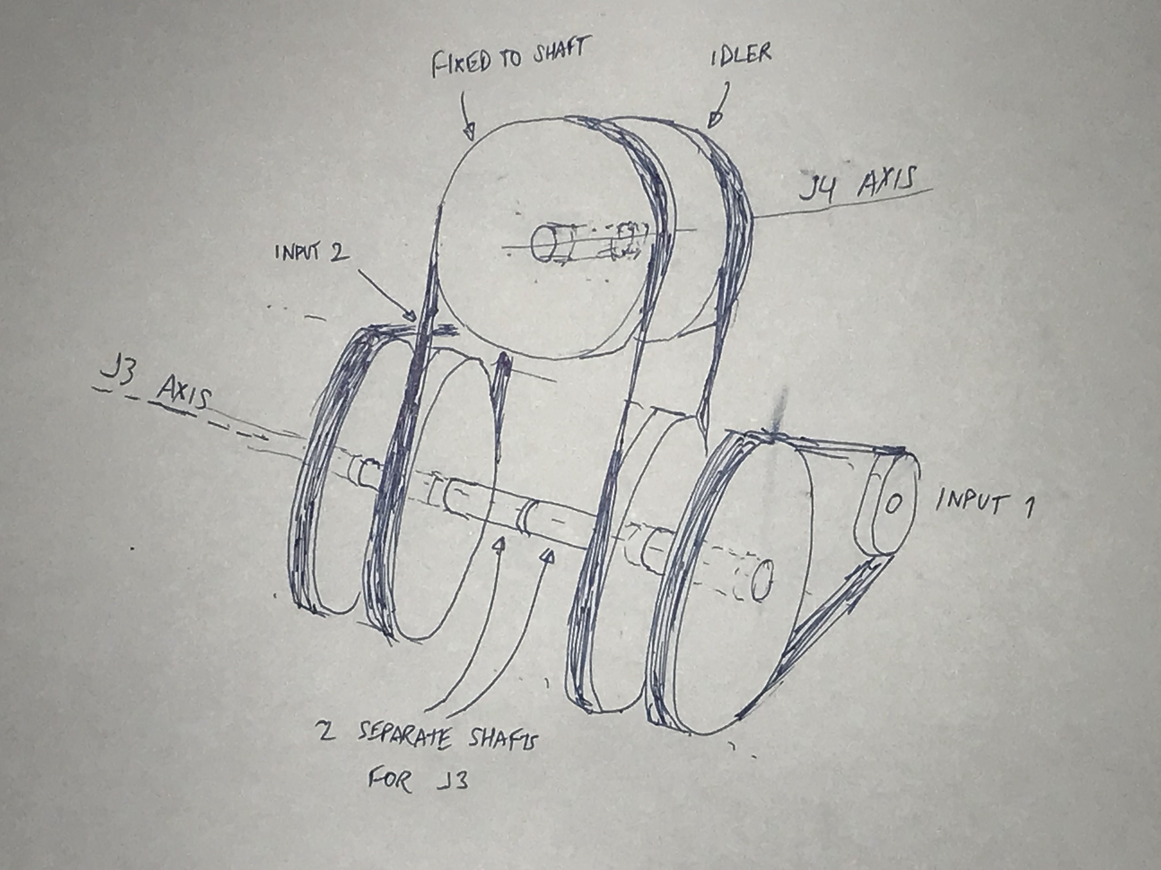
Here is a diagram of the mechanism. I've omitted the structure and bearings for simplicity:
![]()
The mechanism works as follows:
- Two motors (input 1 and input 2) each drive one of the two J3 outer pulleys, which are on separate collinear shafts.
- The J3 outer pulleys transmit the power to their corresponding J3 inner pulley
- The J3 inner pulleys are coupled to the J4 pulleys with a single belt. (the belt has four quarter twists to change direction between the J3 and J4 pulleys)
- The J4 pulleys share the same shaft, but only one of the pulleys is coupled to the shaft. The other pulley is an idler.
- When the two motors are running at equal speed in the same direction, the J4 pulleys cannot turn, and so force J3 to turn
- When the two motors are running at equal speed in opposite directions, the J4 pulleys turn (in opposite directions), driving J4. J3 remains stationary.
- If we add some proportion of opposing and similar input motions, we can achieve any desired simultaneous motion on J3 and J4
While the idea behind the mechanism may seem relatively simple, the design is not.
The original design used two collinear shafts end-to-end, but since these shafts cannot resist a bending moment, the whole mechanism would have the tendency to flex, which is a major issue. Considering the construction of the arm, which should be quite rigid, it may not be a huge problem, but it would certainly reduce the rigidity and repeatability of the arm's motion.
In summary, the main difficulties are:
- Effectively constraining the J3 shafts to ensure rigidity - if the two shafts are allowed to flex even a little, the design will not work
- Designing links (out of 3mm CF sheet) that are adequately rigid and lightweight
- Having space to put encoders (CUI AMT102 or similar)
- Coming up with a design that is able to be assembled without magical tools
I have spent the past three weeks thinking almost exclusively about this complication.
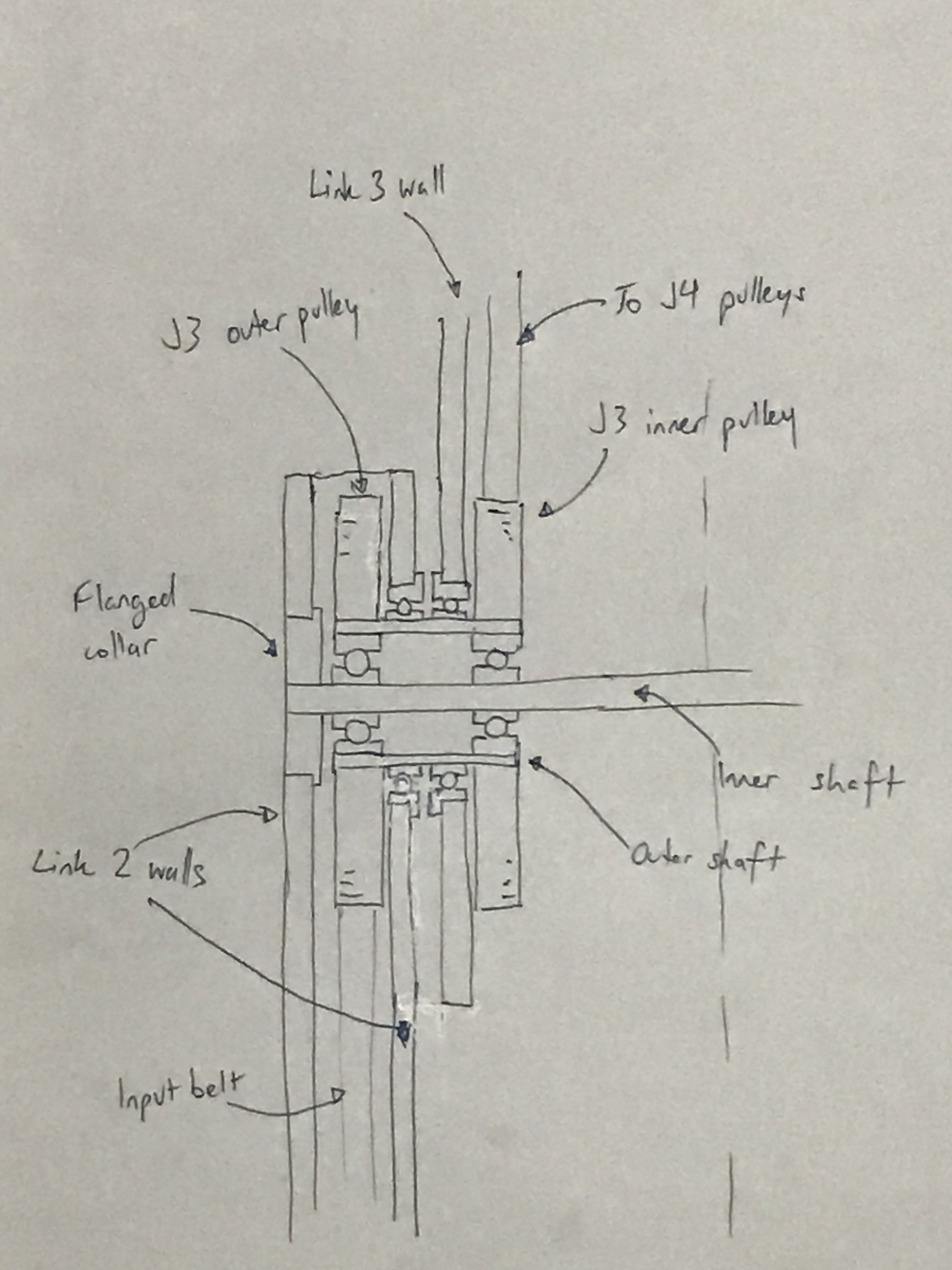
The conclusion that I've come to is that we need to use "shaft-inside-a-shaft" (aka nested shaft) construction, as below: (apologies for the bad drawing)
![]()
(All interfaces between pulleys, shafts and bearing races are bonded with Loctite 638)
This solution will definitely do the job, but it require four additional bearings, as well as the two hollow shafts for either side of J3. Also, it requires a lot more assembly effort.
As I mentioned, I've been working on this complication for 3 weeks now, and I'm all out of ideas.
If anyone can think of a simpler solution to this problem, please post and let me know.
-
Design refinements - shaft hardware
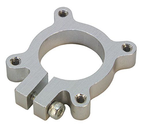
04/29/2018 at 06:32 • 0 commentsOver the past few days I've been mulling over ways to reduce the cost, complexity and width of the joints. Pictures of my current design show joint 3 - you can see in the pictures that the joint is quite wide due to the kind of hardware I'm using for holding bearings in place (clamping hubs):
![]()
The clamping hubs are tightened around the OD of the 608ZZ bearings, which are bonded to the shaft. This is not the intended usage for these hubs (they are designed for clamping onto a length of tube). Additionally, they are overpriced and not widely stocked.
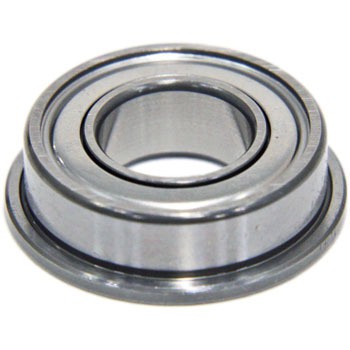
I have decided to replace these clamping hubs with low-cost F688ZZ flanged bearings that will be bonded to the shaft, and press-fit into the CF frame:
![]()
These bearings are somewhat narrower than the 608ZZ bearings, and will sit within the walls of the frame. For walls with a 4mm thickness, these bearings will only add 1.1mm width once fitted (compared to the additional ∼10mm width of the clamping hubs).
The top and bottom plates of the frame will constrain the collars/bearings laterally so that there is no side-to-side slipping on the shaft.
This design will make belt replacement a little bit more involved (i.e. the user would need to partially disassemble the frame to be able to replace a belt), but I think the benefits vastly outweigh this minor inconvenience.
I will also be modifying the design so that the arrangement of each joint is a lot neater, and more similar to the design of commercial robotic arms.
I will publish a new design reflecting these changes soon.
Please feel free to comment about any design ideas you have... you might spot something I've missed, or have an idea that greatly improves the performance of the design.
RM1 - An Affordable Industrial Robotic Arm
A serious 6-axis robotic arm that performs on-par with commercial robotic arms, but costs less than $1000 to build.