-
And doctor said...
10/05/2016 at 16:42 • 0 commentsSo we built probably cheapest ECG in the world, and it seems to work.
But does it really work?
Well, I wouldn't bet my life on it:)So we made a call to association Big heart to small heart, a non-profit, humanitarian organization of doctors, health professionals and parents of children with congenital heart faults and other heart diseases, who happen to know 10000 children who might need such a device.
They connected us to doctor Hrvoje Kniewald, cardiologist at Department of Pediatric Cardiology in Zagreb, and made appointment.
To our surprise, we were greeted by six doctors!
Small room was full of people and we didn't even have opportunity to demontrate the device in action. But we did show them the device, and screenshots.
The conclusion was, YES, it works!
And, might be especially useful in one use case: arrhythmia that occurs rarely.
See, it's easy if you have heart condition and you know you have it. You get to your doc, he scans you and prescribes whatever necessary. But if your heart sometimes, just sometimes behaves, till you get there readings seem fine.
Doctors have put it very simple for us:
that's when healthy kid suddenly dies.But, personal ECG allows to hook up fast, record the readings, and send the data to doctor by e-mail.
Err, what file format do you expect?
Don't bother with that, just send us the data, we'll deal with it.
Fine, we'll just record to CSV.
And we do. We also got few technical tips, like how to properly draw ECG, all implemented already.
Of course, there's some cons.
First, electrodes are impractical, especially one that needs to be tied to leg. If that takes too long, arrhythmia might pass.
Well, Olimex already sells different kind of electrodes, like, real ones. We did not purchase these for they are not open source:)Second, the device requires PC to work. PC supplies it with electric power, but also with processing power, for it runs the software to display and save the data.
Well, we already demonstrated one way to build a portable DIY ECG, and this is clearly out of scope for this project.Third, it's not very precise device. It does record PQRST - just enough for majority of people with heart conditions. But small beats outside of PQRST cannot be distingushed from noise.
This might be issue with our filters. So if anyone out there can do better, feel free to do it!To conclude this log, I'll just say it's a good feeling knowing you maybe made a life saver.
You should try it yourself;)
But make no mistake, this is not a medical device! Certification procedures actually mean something, especially for medical devices: they mean you can bet your life on it.
Big thanks to Big heart to small heart and their good doctors.
-
A box for cardiotron
10/05/2016 at 11:40 • 0 commentsHaving an open PCB around as a medical device is rather impractical. Aside from being easily damaged, these devices are expected to come in contact with people who are not professionals used to dealing with electronic components. Having them placed on conductive surfaces, tossed around from time to time and subjected to all manners of "everyday" abuse is expected.
To that end, we designed a very simple, but sturdy 3D printed box to protect the electronics. It is based on a popular open SCAD solution by Kelly Egan, modified to fit a slightly different Arduino clone board, the ECG shield and a port for electrodes.
The board is screwed into the box using 3 screws, and those are the only 3 contact points to the box, other than the cables when plugged in. Lid is snapped on firmly and held by friction. If the box is dropped with enough force (roughly the force of a grown man slamming it into the ground on purpose), the lid may snap off. Using a lever against the four corners of the box will easily snap the lid off step by step.ž
All in all, it is a simple solution to a simple problem.
-
The PC side of things
10/04/2016 at 10:13 • 0 commentsFiddling with the ECG signal, I used only two tools - python and matlab. Python does a simple script which draws the signal in real time and measures the RR interval (but does not detect QRS - that's done on the MCU!), as well as saves all the data into a CSV file. A very convenient library I use to draw things on the screen is pygame. It is considerably more powerful than what's realistically needed for this software to work, but drawing things in real time is very easy using its tools.
I use matlab mostly for trying out filters and signal processing methods to use on the MCU, as well as to display results. It's a convenient tool for testing DSP algorithms. Other than the overlap&average method which is still a bit too hard for ATmega328's memory capacity, nothing really exciting is going on.
All this code can be found on our github, though most comments are in Croatian... for now!
-
IoT ECG with LCD?
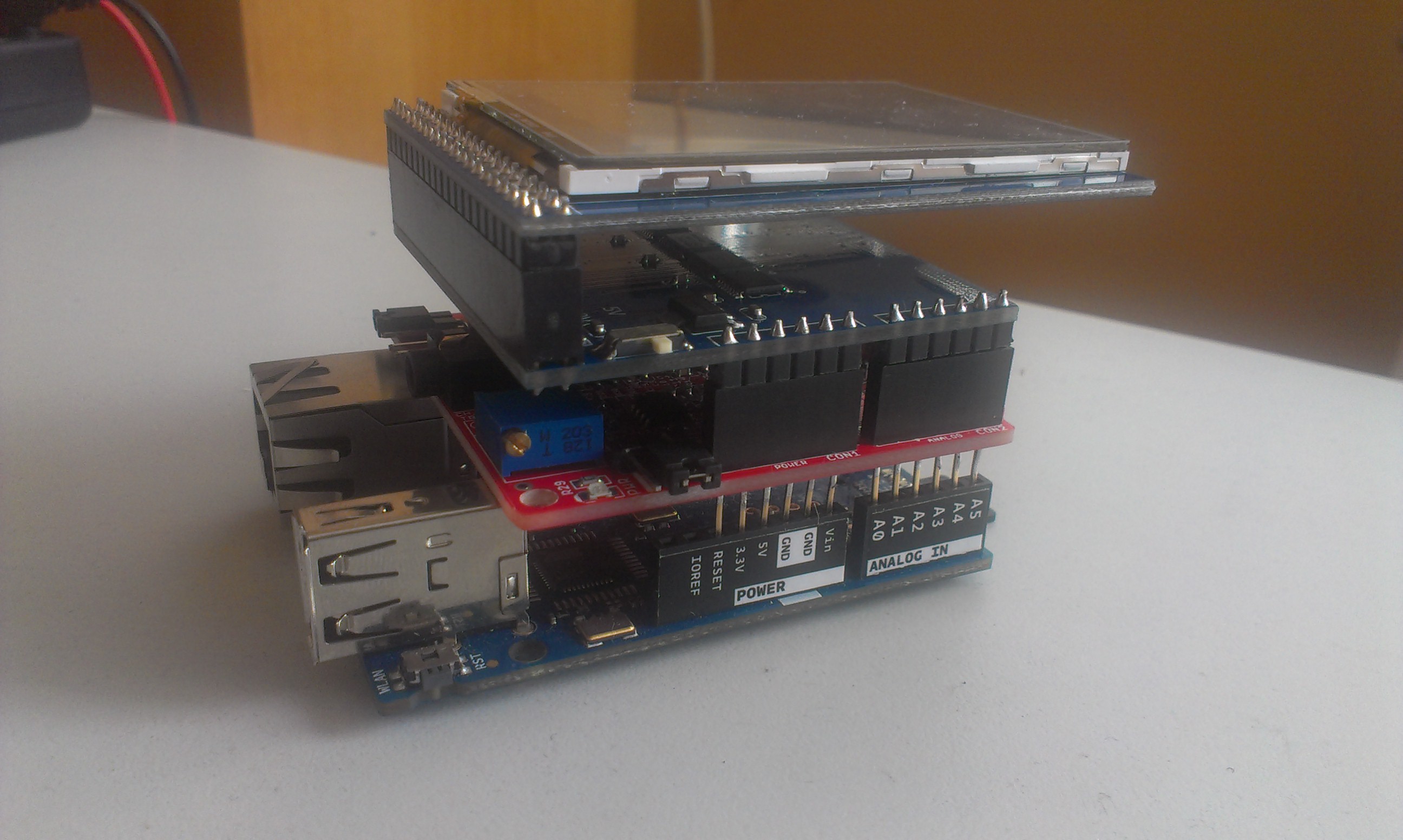
10/03/2016 at 11:14 • 0 commentsHow about we plug EKG-EMG shield into Arduino Yun, and stack an LCD touch screen on top of it?
![]()
That device could:
- publish to internet in real-time
- provide touch-screen user interface
- display the reading
I played a bit with it. To make long story short, let me jump to conclusions.Good stuff:
LCD is quite handy, for you need to be still during measurement.
EKG-EMG shield allows to select input pins, so it's fully stackable, and does not interfere with other shields
With some power supply, this could really be a DIY IoT ECG, fully portable, able to store data to SD card too.
Yun also has enough CPU power to filter and display the data, and supports any programming language of choice.Bad stuff:
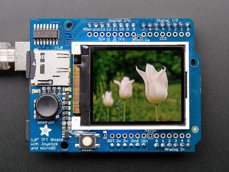
Touch screen is pretty much useless, for it is too small. Any UI components large enough to press them, don't leave enough space to display actual readings. Furthermore, touch is interrupt, ECG is interrupt, and displaying the data takes time - all that makes development considerably harder. Bottom line - better give up touch screen and use simple buttons.
Or, here's what I'd ideally put on top:![]()
Anyway, we'll are going to plug cardiotron to PC, so I don't intend to purse this further.
Here's some code in case anyone's interested.
#include <UTFT.h> #include <UTouch.h> #include <compat/deprecated.h> #include <FlexiTimer2.h> // EKG STUFF // All definitions #define NUMCHANNELS 6 #define HEADERLEN 4 #define PACKETLEN (NUMCHANNELS * 2 + HEADERLEN + 1) #define SAMPFREQ 256 // ADC sampling rate 256 #define TIMER2VAL (1024/(SAMPFREQ)) // Set 256Hz sampling frequency #define LED1 13 #define CAL_SIG 9 // Global constants and variables volatile unsigned char TXBuf[PACKETLEN]; //The transmission packet volatile unsigned char TXIndex; //Next byte to write in the transmission packet. volatile unsigned char CurrentCh; //Current channel being sampled. volatile unsigned char counter = 0; //Additional divider used to generate CAL_SIG volatile unsigned int ADC_Value = 0; //ADC current value // LCD STUFF // Declare which fonts we will be using extern uint8_t SmallFont[]; // Set the pins to the correct ones for your development shield UTFT myGLCD(ITDB24E_8,A5,A4,A3,A2); UTouch myTouch( 15,10,14, 9, 8 ); // JOE's stuff int sequence = 0; volatile unsigned int values[6]; int prev1 = 0; int prev2 = 0; int prev3 = 0; unsigned int touchX, touchY; void setup() { setupLCD(); setupTouch(); setupEKG(); } void setupTouch() { myTouch.InitTouch(); myTouch.setPrecision(PREC_MEDIUM); } void setupEKG() { noInterrupts(); // Disable all interrupts before initialization // LED1 pinMode(LED1, OUTPUT); //Setup LED1 direction digitalWrite(LED1,LOW); //Setup LED1 state pinMode(CAL_SIG, OUTPUT); //Write packet header and footer TXBuf[0] = 0xa5; //Sync 0 TXBuf[1] = 0x5a; //Sync 1 TXBuf[2] = 2; //Protocol version TXBuf[3] = 0; //Packet counter TXBuf[4] = 0x02; //CH1 High Byte TXBuf[5] = 0x00; //CH1 Low Byte TXBuf[6] = 0x02; //CH2 High Byte TXBuf[7] = 0x00; //CH2 Low Byte TXBuf[8] = 0x02; //CH3 High Byte TXBuf[9] = 0x00; //CH3 Low Byte TXBuf[10] = 0x02; //CH4 High Byte TXBuf[11] = 0x00; //CH4 Low Byte TXBuf[12] = 0x02; //CH5 High Byte TXBuf[13] = 0x00; //CH5 Low Byte TXBuf[14] = 0x02; //CH6 High Byte TXBuf[15] = 0x00; //CH6 Low Byte TXBuf[2 * NUMCHANNELS + HEADERLEN] = 0x01; // Switches state // Timer2 // Timer2 is used to setup the analag channels sampling frequency and packet update. // Whenever interrupt occures, the current read packet is sent to the PC // In addition the CAL_SIG is generated as well, so Timer1 is not required in this case! FlexiTimer2::set(TIMER2VAL, Timer2_Overflow_ISR); FlexiTimer2::start(); // Serial Port Serial.begin(57600); //Set speed to 57600 bps // MCU sleep mode = idle. //outb(MCUCR,(inp(MCUCR) | (1<<SE)) & (~(1<<SM0) | ~(1<<SM1) | ~(1<<SM2))); interrupts(); // Enable all interrupts after initialization has been completed } void setupLCD() { // Setup the LCD myGLCD.InitLCD(); myGLCD.setFont(SmallFont); initScreen(); drawScreen(); } // blink the led during transfer void Toggle_LED1(void) { if((digitalRead(LED1))==HIGH){ digitalWrite(LED1,LOW); } else{ digitalWrite(LED1,HIGH); } } // switch over cal-sig - CHECKME void toggle_GAL_SIG(void) { if(digitalRead(CAL_SIG) == HIGH){ digitalWrite(CAL_SIG, LOW); } else{ digitalWrite(CAL_SIG, HIGH); } } // timer interrupt handler - measure and transfer void Timer2_Overflow_ISR() { // Toggle LED1 with ADC sampling frequency /2 Toggle_LED1(); //Read the 6 ADC inputs and store current values in Packet for(CurrentCh=0;CurrentCh<6;CurrentCh++){ ADC_Value = analogRead(CurrentCh); values[CurrentCh] = ADC_Value; TXBuf[((2*CurrentCh) + HEADERLEN)] = ((unsigned char)((ADC_Value & 0xFF00) >> 8)); // Write High Byte TXBuf[((2*CurrentCh) + HEADERLEN + 1)] = ((unsigned char)(ADC_Value & 0x00FF)); // Write Low Byte } drawValues(); sequence++; if ( sequence >= 320 ) { sequence = 0; //drawScreen(); } // Send Packet for(TXIndex=0;TXIndex<17;TXIndex++){ Serial.write(TXBuf[TXIndex]); } // Increment the packet counter TXBuf[3]++; // Generate the CAL_SIGnal counter++; // increment the devider counter if(counter == 12){ // 250/12/2 = 10.4Hz ->Toggle frequency counter = 0; toggle_GAL_SIG(); // Generate CAL signal with frequ ~10Hz } } void initScreen() { myGLCD.clrScr(); myGLCD.setColor(255, 255, 0); myGLCD.fillRect(0, 0, 319, 13); myGLCD.setColor(0,0,0); myGLCD.setBackColor(255, 255, 0); myGLCD.print("DIY ECG - Joe's Free Stuff", CENTER, 1); drawScreen(); } void drawScreen() { myGLCD.setColor(0, 0, 0); myGLCD.fillRect(0, 14, 319, 239); // Draw crosshairs myGLCD.setColor(0, 0, 255); myGLCD.drawRect(0, 15, 319, 224); myGLCD.setColor(0, 0, 255); myGLCD.setBackColor(0, 0, 0); myGLCD.drawLine(159, 15, 159, 224); myGLCD.drawLine(1, 119, 318, 119); for (int i=9; i<310; i+=10) myGLCD.drawLine(i, 117, i, 121); for (int i=19; i<220; i+=10) myGLCD.drawLine(157, i, 161, i); } void drawValues() { int lead1 = values[0] - values[1]; int lead2 = values[2] - values[1]; int lead3 = values[2] - values[0]; // clear current position myGLCD.setColor(0,0,0); myGLCD.drawLine(sequence,14,sequence,239); // draw lead 1 myGLCD.setColor(255, 255, 255); if ( sequence > 0 ) { myGLCD.drawLine(sequence-1, prev1/5+60, sequence, lead1/5+60); } // draw lead 2 myGLCD.setColor(255, 255, 0); if ( sequence > 0 ) { myGLCD.drawLine(sequence-1, prev2/5, sequence, lead2/5); } // draw lead 3 myGLCD.setColor(0, 255, 255); if ( sequence > 0 ) { myGLCD.drawLine(sequence-1, prev3/5+20, sequence, lead3/5+20); } prev1 = lead1; prev2 = lead2; prev3 = lead3; if ( touchX != -1 || touchY != -1 ) { //myGLCD.print("DIY ECG - Joe's Free Stuff", CENTER, 1); myGLCD.setColor(255, 255, 255); myGLCD.drawLine(0,0,touchX,touchY); touchX = -1; touchY = -1; } } void loop() { __asm__ __volatile__ ("sleep"); } -
Basic operation and limitations
10/03/2016 at 10:40 • 0 commentsECG shield
The first thing to note about this shield is that it provides 1 measurement channel over its differential amplifier. The shield unfortunately contains a bandpass filter with cutoffs at 0.16Hz and 40Hz. It is stackable, but stacked shields seem to require their own electrodes which sounds like it would get very messy very fast.
Method of measurement
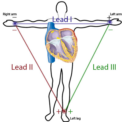
![]() Image above shows the standard electrode setup. Leads 2 and 3 are inputs to the differential amplifier which then outputs the potential across lead 1.
Image above shows the standard electrode setup. Leads 2 and 3 are inputs to the differential amplifier which then outputs the potential across lead 1.A standard heartbeat
![]()
The image above shows a standard heartbeat as recorded on 1 channel ECG. The heartbeat contains 5 notable features marked P, Q, R, S and T. Ideally, we want to reconstruct all 5, but that is not an easy task with the ECG shield we're using. Read on to find out why. Still, even if we don't succeed in getting a clear image of all the features, extracting even just the QRS Complex would make this device a useful tool.
Modern ECG standard (as seen from this document)
Regarding the useful information in ECG frequency spectrum, it is ideal to have the lower cutoff as low as 0.05Hz, but this requirement can be relaxed up to 0.67Hz for some applications. It is worth noting that increasing the lower cutoff frequency causes considerable deformation of the ST segment. The deformation we get wouldn't really fit into the "considerable" category, but is is certainly there. When it comes to the upper limit, for adults, 100Hz is recommended while in babies up to 250Hz is required. This is where the Olimex ECG shield falls flat with its lazy 40Hz cutoff. The designers are not entirely to blame, as (really) old hospital ECGs used to run at the same frequency range, but nowadays we would like more measurements per second. One pretty obvious reason to cut off at 40Hz is the 50/60Hz power noise. Creating a multi-stage filter which deals with that separately while still preserving the higher frequencies was probably impractical so they went with the simple band pass.
What we do with the signal
Since our signal is already filtered in hardware, there is no need for (or use of) further filtering in the frequency range of the filter itself. When looking at the unfiltered signal, I noticed that, while it probably has some effect on the amplitude of the 50Hz interference, the hardware filter doesn't completely remove it. It does however get rid of anything higher pretty effectively. For this reason I had no qualms applying a low pass 4th order Butterworth filter which cuts off at 45Hz to do away with the power noise once and for all. This also has an added benefit of removing much of the high frequency ADC noise.
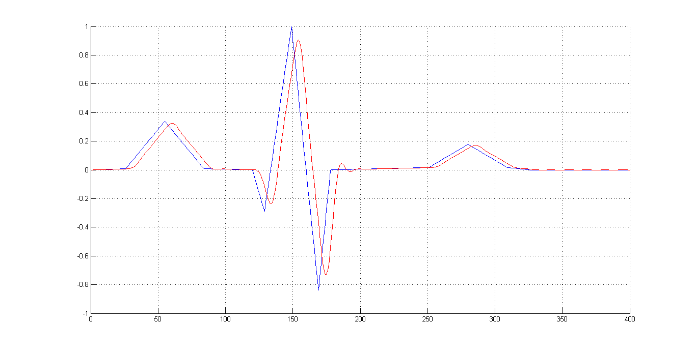
To test the effects of our filter, I pushed an idealized version of PQRST through it as seen in the image below:
![]()
This gives us a good idea of the kinds of deformations we can expect - varying delays among features will distort our idea of the timings - the fastest QRS complex sees the highest delay so it is slightly pushed towards T. Also, since P is slightly faster than T, its delay is higher so the overall duration of the complex is slightly shortened. Looking at amplitudes, there is slight damping, again most prominent at the QRS due to it having the highest amount of high-frequency content. Another thing to notice is slight ringing after the QRS.
Overall, it seems like a small price to pay for getting rid of most of the high frequency trash introduced by the measurement hardware, especially considering that the useful high frequency content is already destroyed by the shield's hardware filter anyway.
There is one effect that requires special attention when measuring ECG - the baseline drift. This is an extremely low frequency noise signal which effectively moves your ECG up and down very slowly. A possibly somewhat unusual, but very effective way of dealing with it is running a very slow low-pass filter which effectively calculates the average value of its input, and subtracting its output from the overall signal. Generally, this may not keep the zero where it's supposed to be but it almost guarantees that no damage will be done to the shape of any individual PQRST, and makes sure they're all level with each other.
How it looks in action
![]()
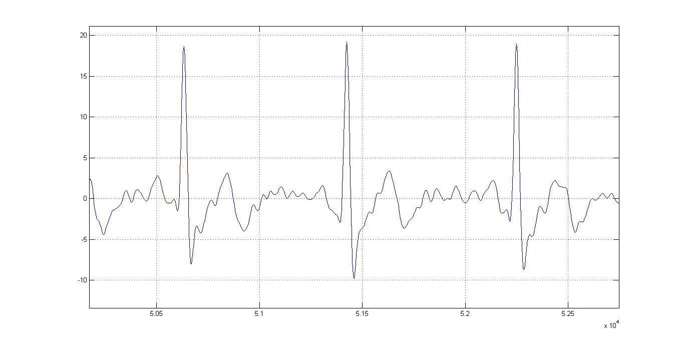
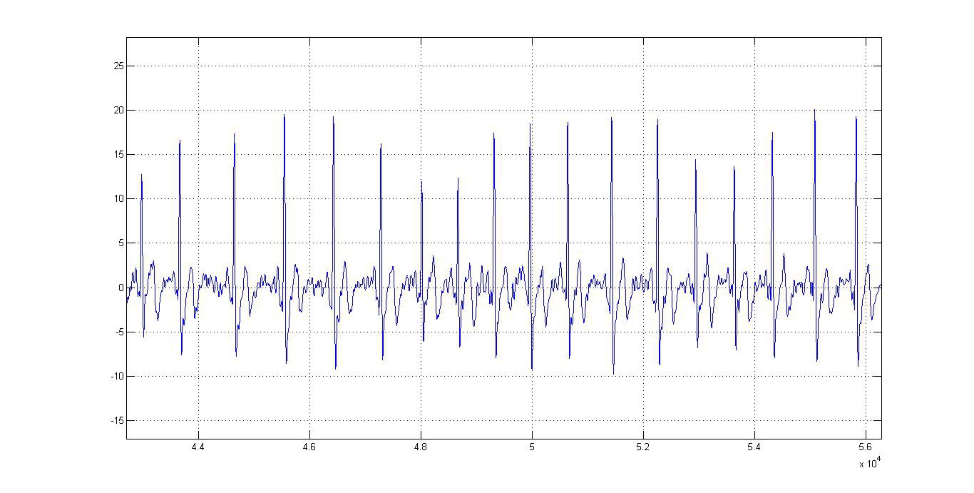
This is what the device puts out over serial. Some high frequency wobble is visible - this is because further stepping onto the higher frequencies would hurt the form of QRS too much, so I let them live - for now.
A rather fun thing to notice is how amplitude and frequency (though frequency drift may not be readily visible from the image below) correlate with breathing. Don't make fun of yoga classes! :)
![]()
Obviously, it is hard to say anything exact about the P and T forms when it comes to diagnostics, but QRS is not too bad. To make things better, while measuring timings between two different features is a bit dodgy, measuring the frequency is actually very accurate because two same features are generally delayed and deformed by the same amount. This makes the device a useful tool in tracking arrythmias. Also, any less subtle deviation from the standard PQRST will be noticeable in real time.
Pulse detection
We do pulse detection by looking for a QRS complex. This is done by raising different flags and deciding whether what the device is looking at really is a QRS or not. Flags can differ - from the naive amplitude check (amplitude > threshold -> QRS) to a bit sneakier rise rate check (derivation > threshold -> QRS) to a bit more elaborate ones (it's only QRS if more than Xms has passed since the last one detected) and so on. We use a combination of amplitude, 1st and 3rd derivation treshold flags.
Offline signal processing
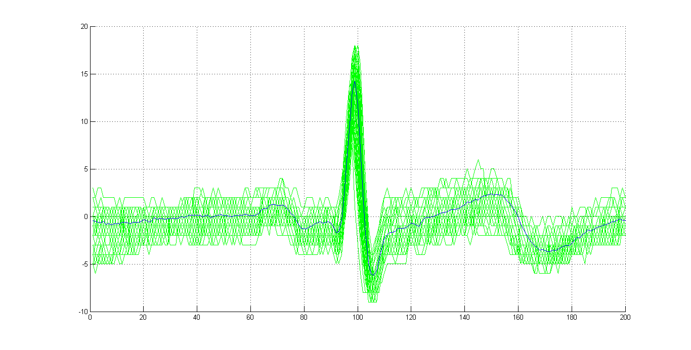
If further precision is needed, we resort to a sneaky offline technique which combines our ability to accurately detect the position of QRS with a bunch of captured measurements into a powerful noise suppresion tool - overlap&average. Here's what it does in practice:
![]()
Pretty neat eh?
-
First measurement
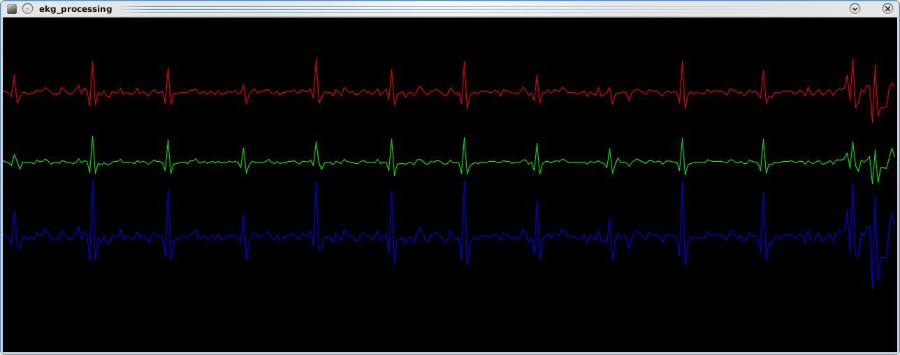
10/01/2016 at 13:02 • 0 commentsAfter assembling the device, I wrote a simple Processing sketch to see what I can get from it. And this is what I got:
![]() Seems like my heart worked:)
Seems like my heart worked:)
Mess on the right side is when I started moving my hand to reach the keyboard.
Well, good so far.
 mikrotron

 Seems like my heart worked:)