oneohm
-
Video is up!
10/10/2016 at 04:40 • 0 comments -
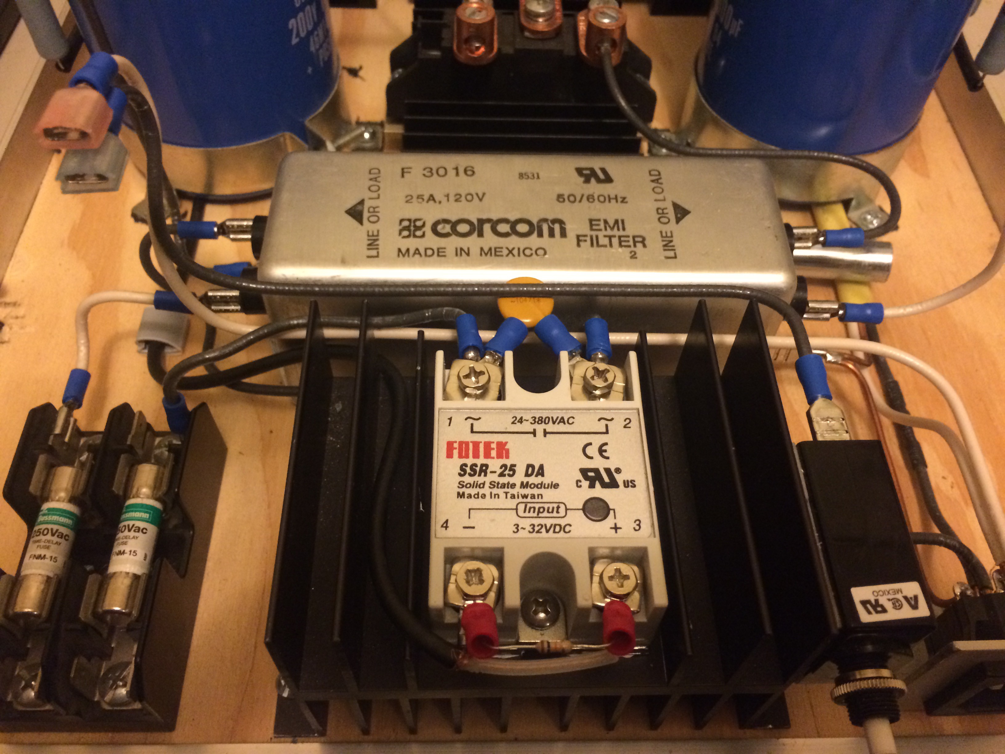
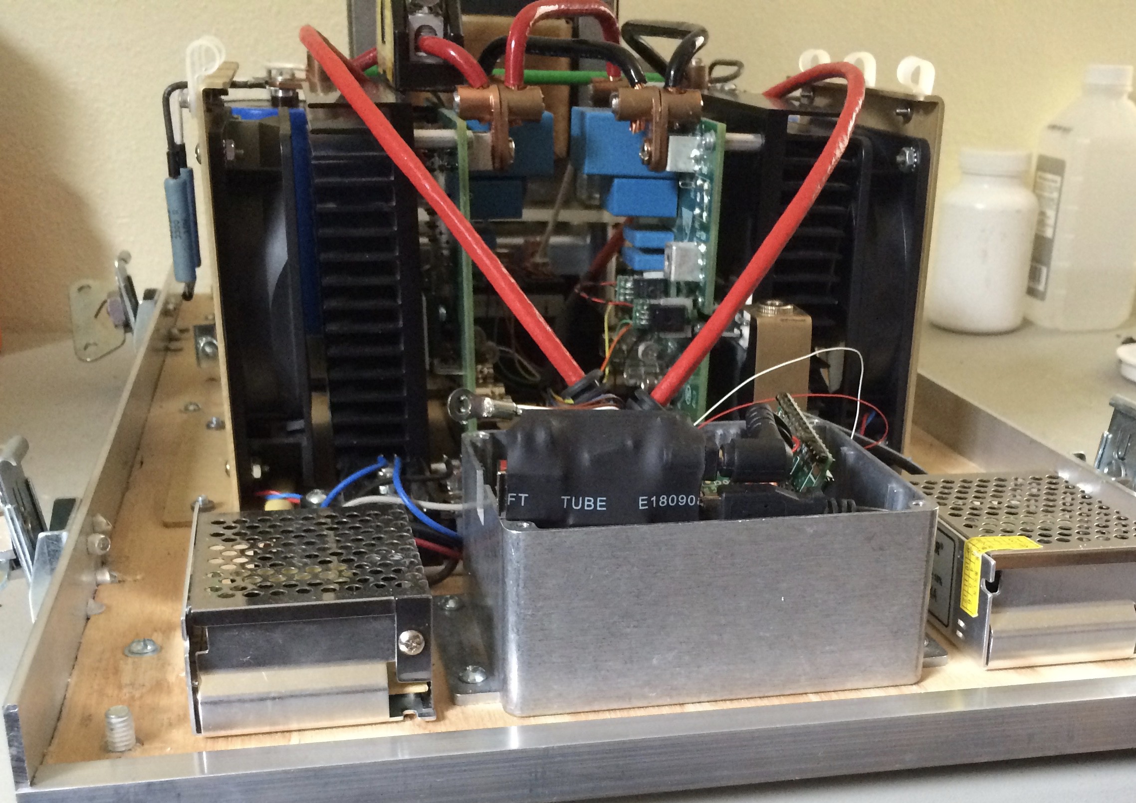
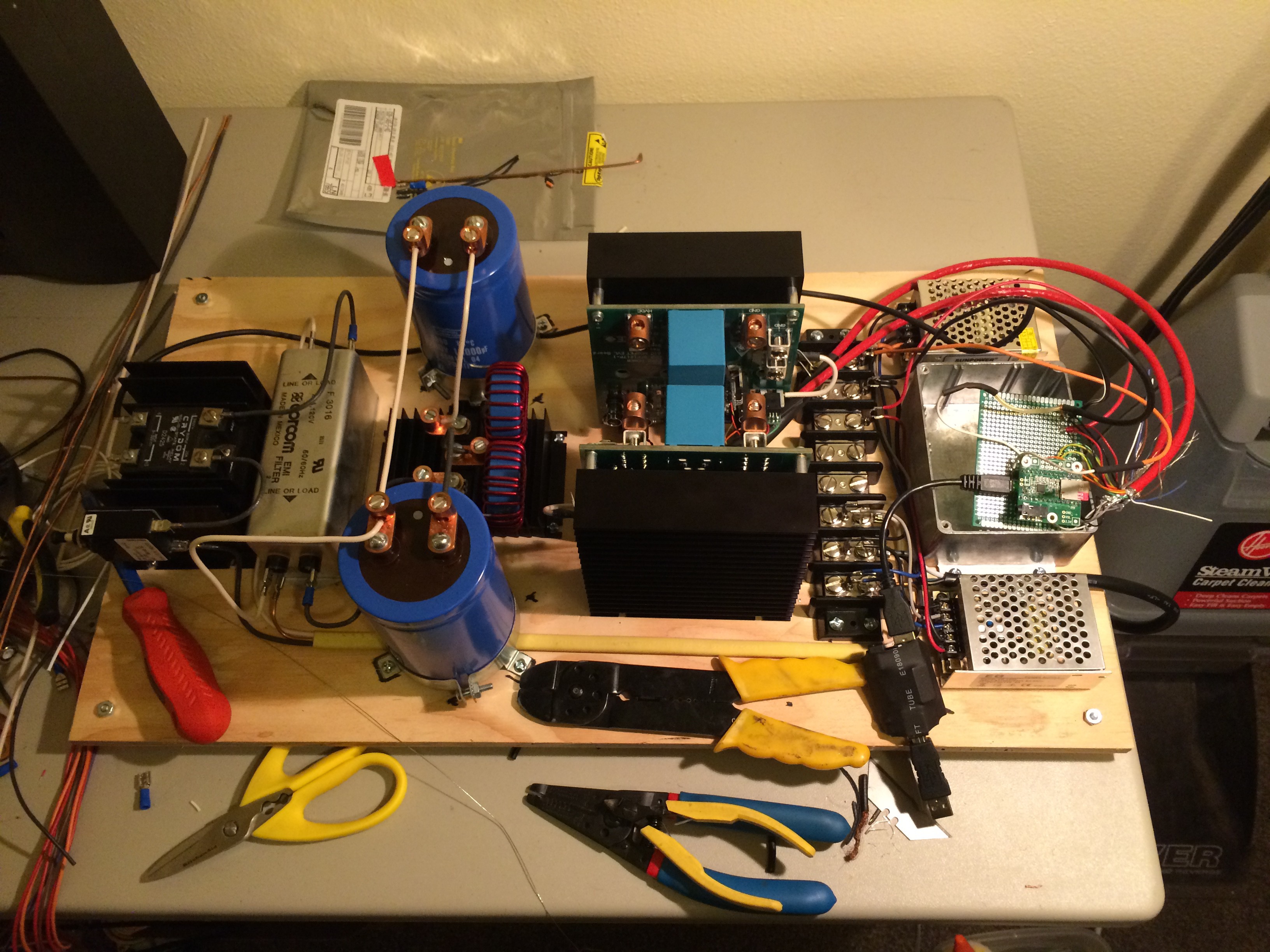
A look under the isolation transformer
10/10/2016 at 04:11 • 0 commentsA look under the isolation transformer.
The wire routing has changed since this was taken, but this shows the layout of the components that are normally obscured by the transformer.
![]()
-
Heart Surgery
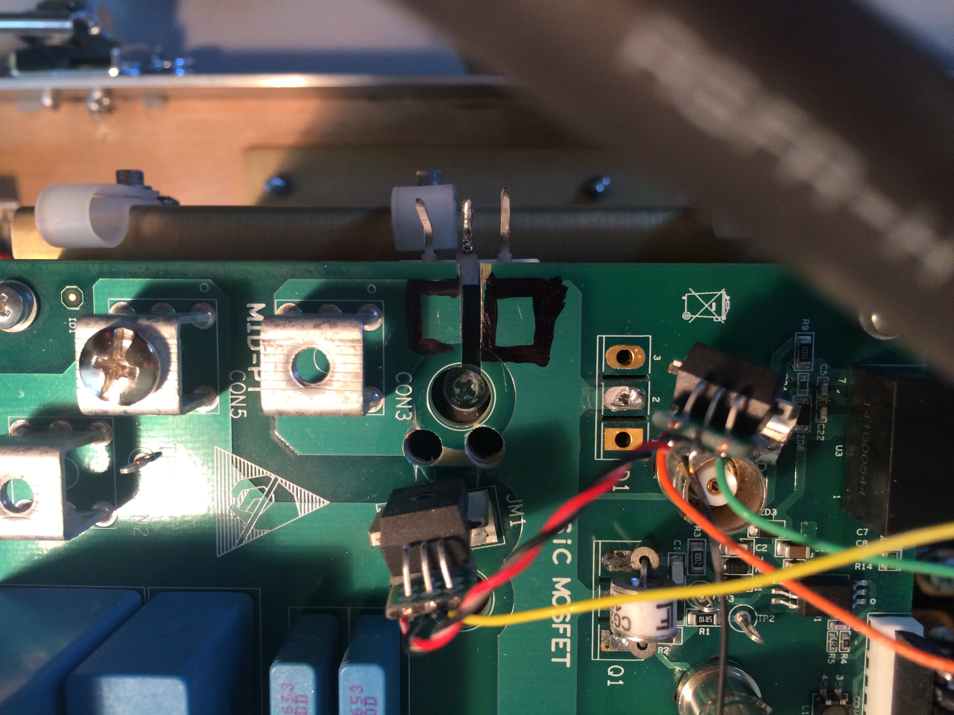
10/04/2016 at 23:34 • 0 commentsTo monitor the current I modified the boards to accept some Allegro high current sensor ICs.
http://www.allegromicro.com/en/Products/Current-Sensor-ICs/Fifty-To-Two-Hundred-Amp-Integrated-Conductor-Sensor-ICs.aspxThe board has a hefty jumper connection (JM1) to monitor current to ground, but I also wanted to to measure output current (for some experiments these will not be the same).
This turned out to be more difficult that just cutting a trace as power was also being routed on some of the internal layers. Two carefully drilled holes and a slot cut through the board. These were later insulated with some clear acrylic sealant (nail polish).
![]() Another angle:
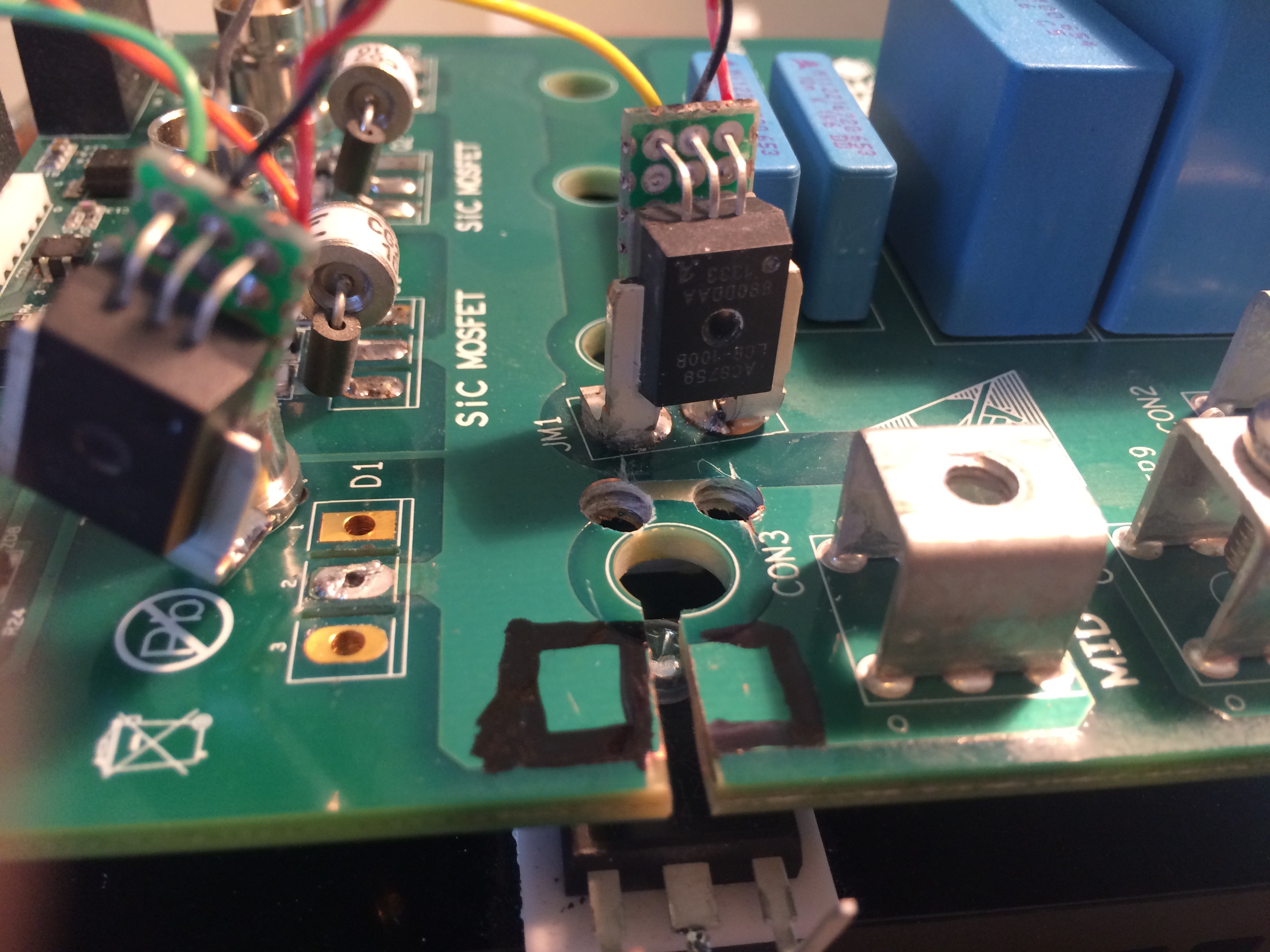
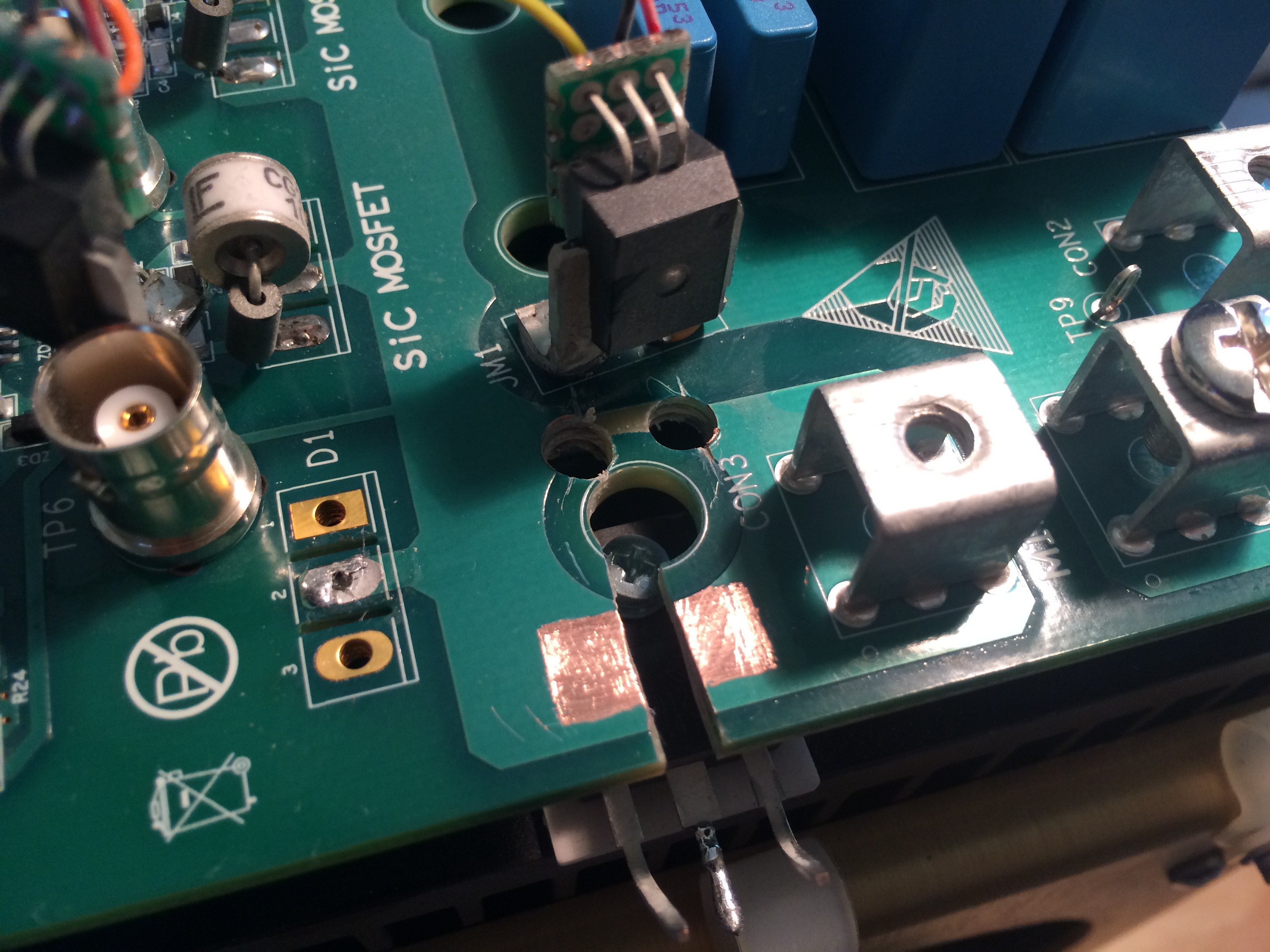
Another angle:![]() I carefully removed the solder mask to create a footprint for the second current sensor:
I carefully removed the solder mask to create a footprint for the second current sensor:![]() Here you can see them mounted to the module on the right:
Here you can see them mounted to the module on the right:![]()
-
The Heart
10/04/2016 at 22:44 • 0 commentsThe heart of the machine consists of two evaluation kits for the CREE 1200V SiC MOSFET and SiC Schottky diode. They come with really nice matched heat sinks. The high power devices bolt directly to the heat sink through matched holes milled into the PCB.
Evaluation Board details:
- 900V max.
- 10kW /w a cooling fan
- > 300 kHz
- +12V aux supply
- 2 input PWM channels
-Digikey product page: http://www.digikey.com/product-detail/en/cree-wolfspeed/KIT8020-CRD-8FF1217P-1/KIT8020-CRD-8FF1217P-1-ND/5027643![]()
-
Control Box
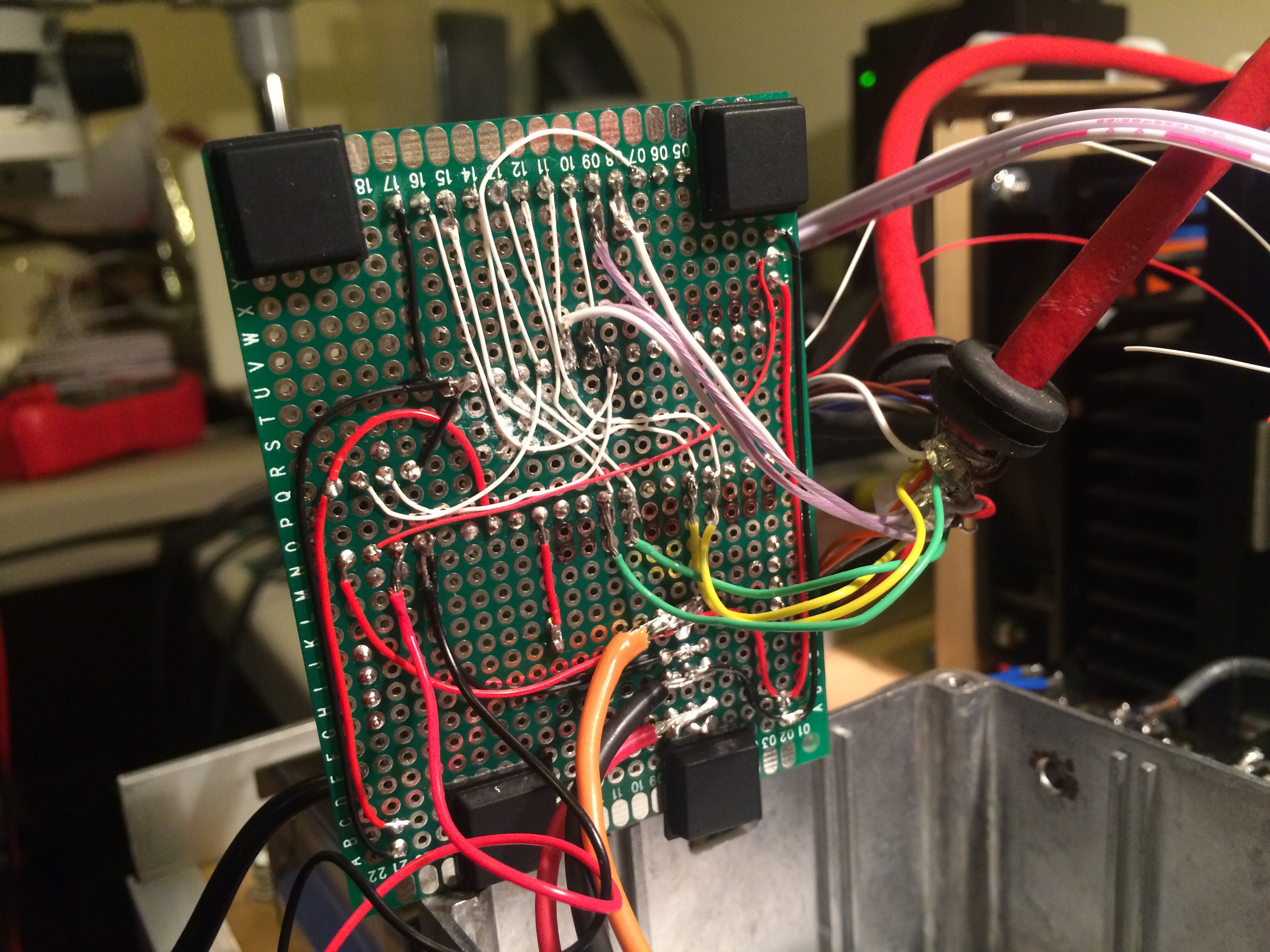
10/03/2016 at 03:42 • 0 commentsHere are the brains - a Teesnsy 3.2 with an audio expansion board (w/ microSD slot):
I/O and power are protected by the "isolation module".![]()
And the reverse:
![]()
-
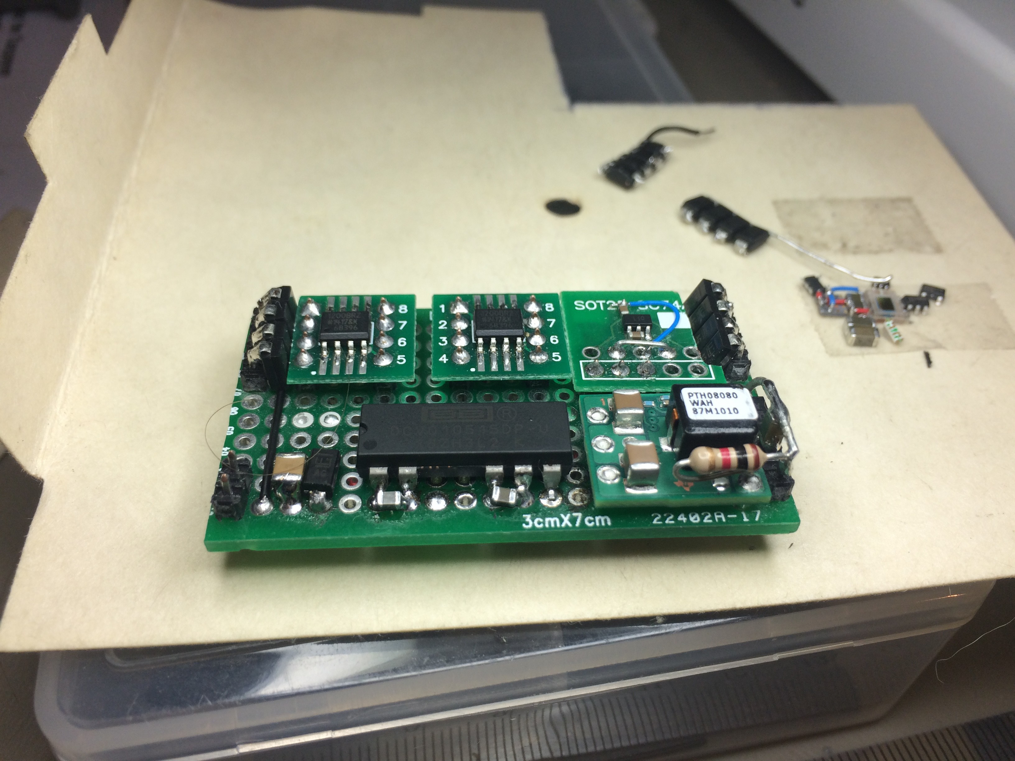
Isolation Board
10/03/2016 at 02:55 • 0 commentsHere are a few of the components that ended up on the isolation board:
![]()
Close to the current configuration (not to worry - specifics are on the way)
![]()
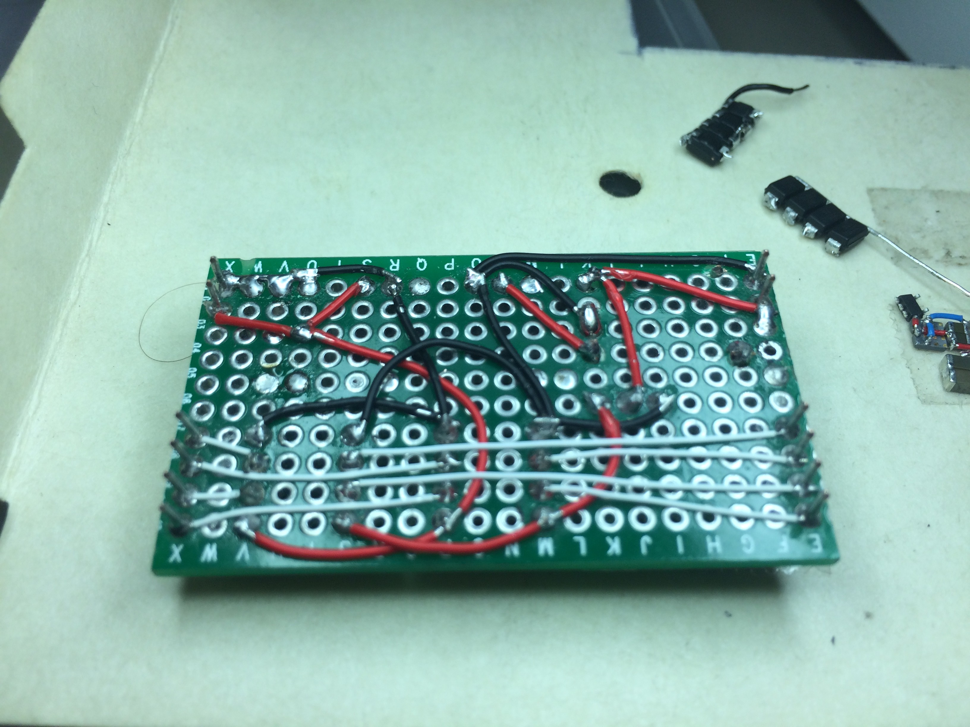
The bottom:
![]()
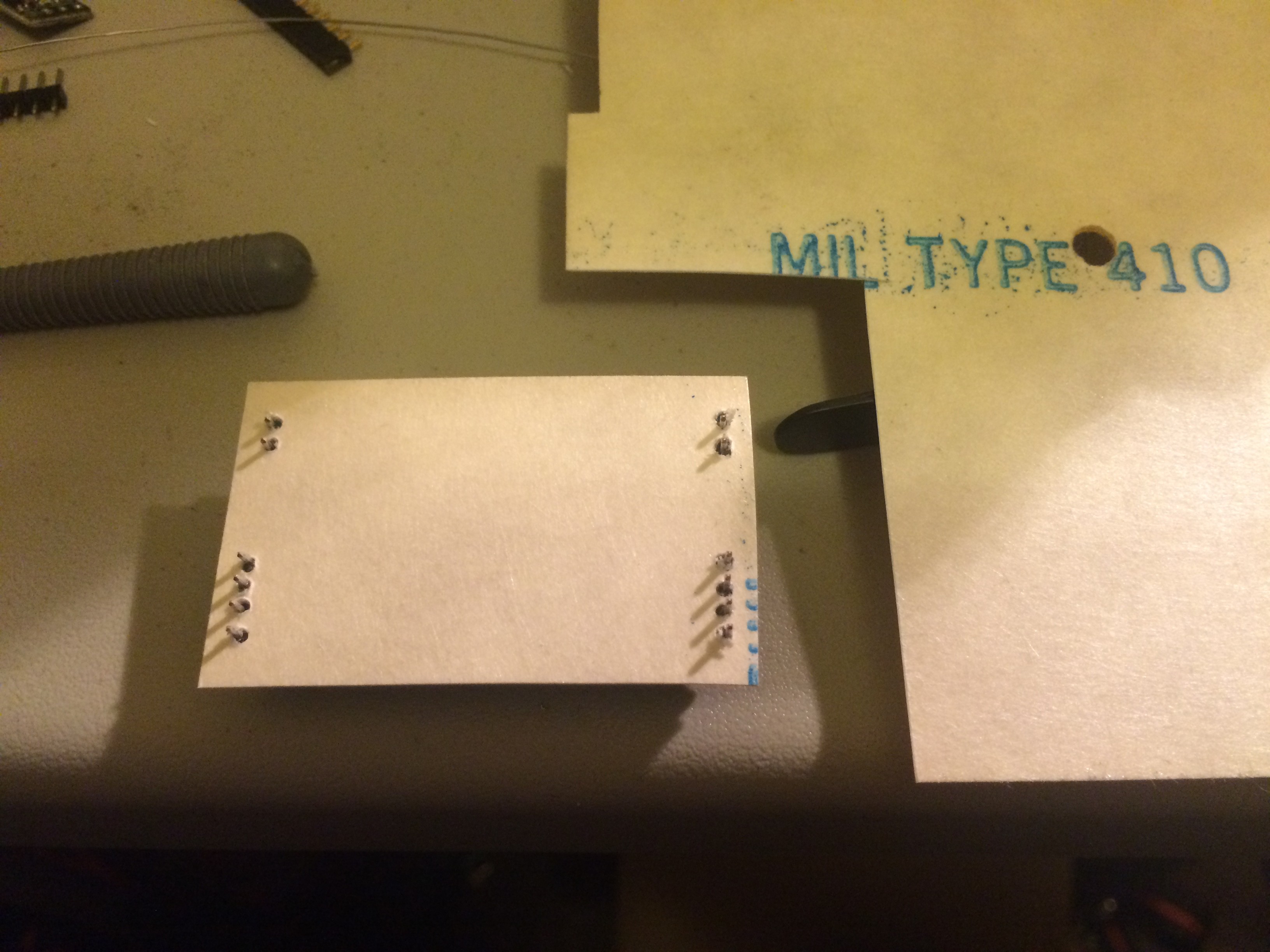
Bottom with protective sheet in place:
![]()
-
It takes shape
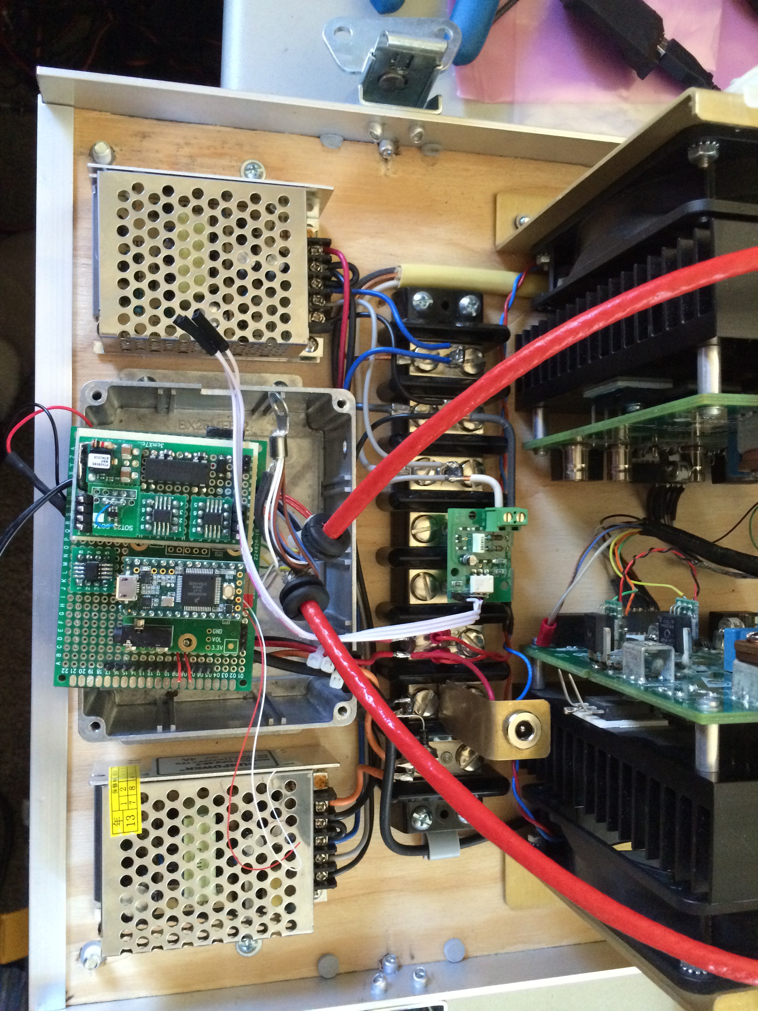
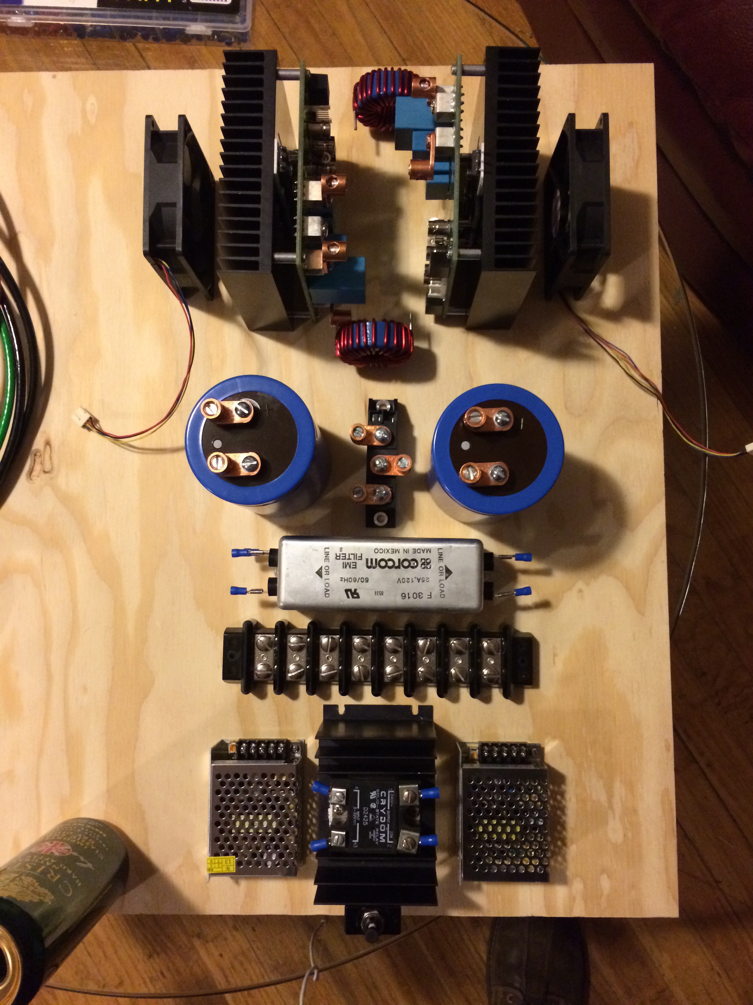
10/03/2016 at 02:07 • 0 commentsFinalized layout with most components bolted to the plywood base at this point.
![]()
-
Mocking up the component layout
10/03/2016 at 02:03 • 0 commentsHere is one of the early layouts, it has been through several iterations.
![]()
-
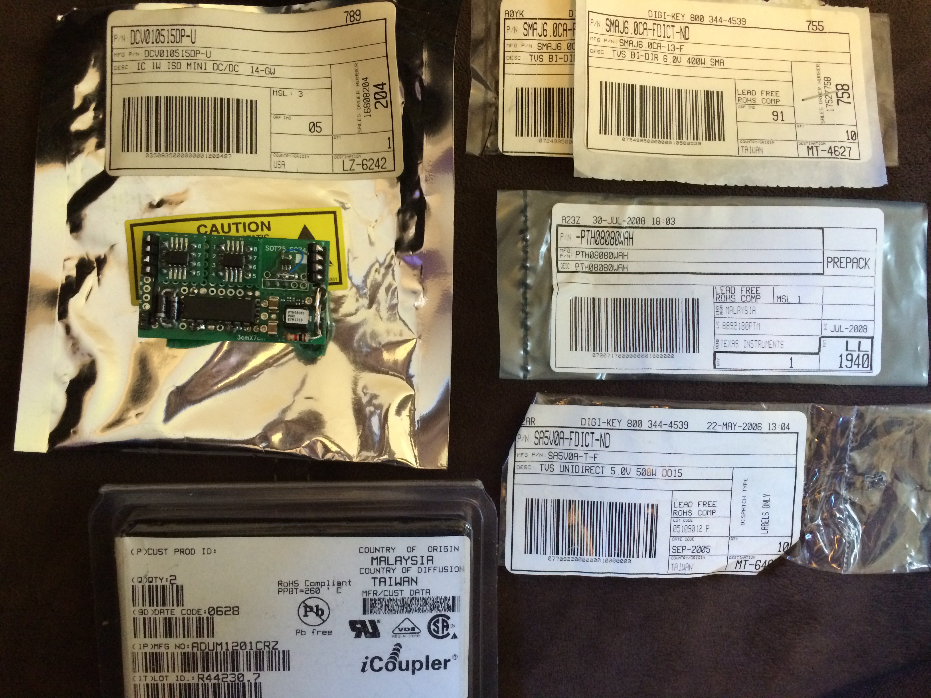
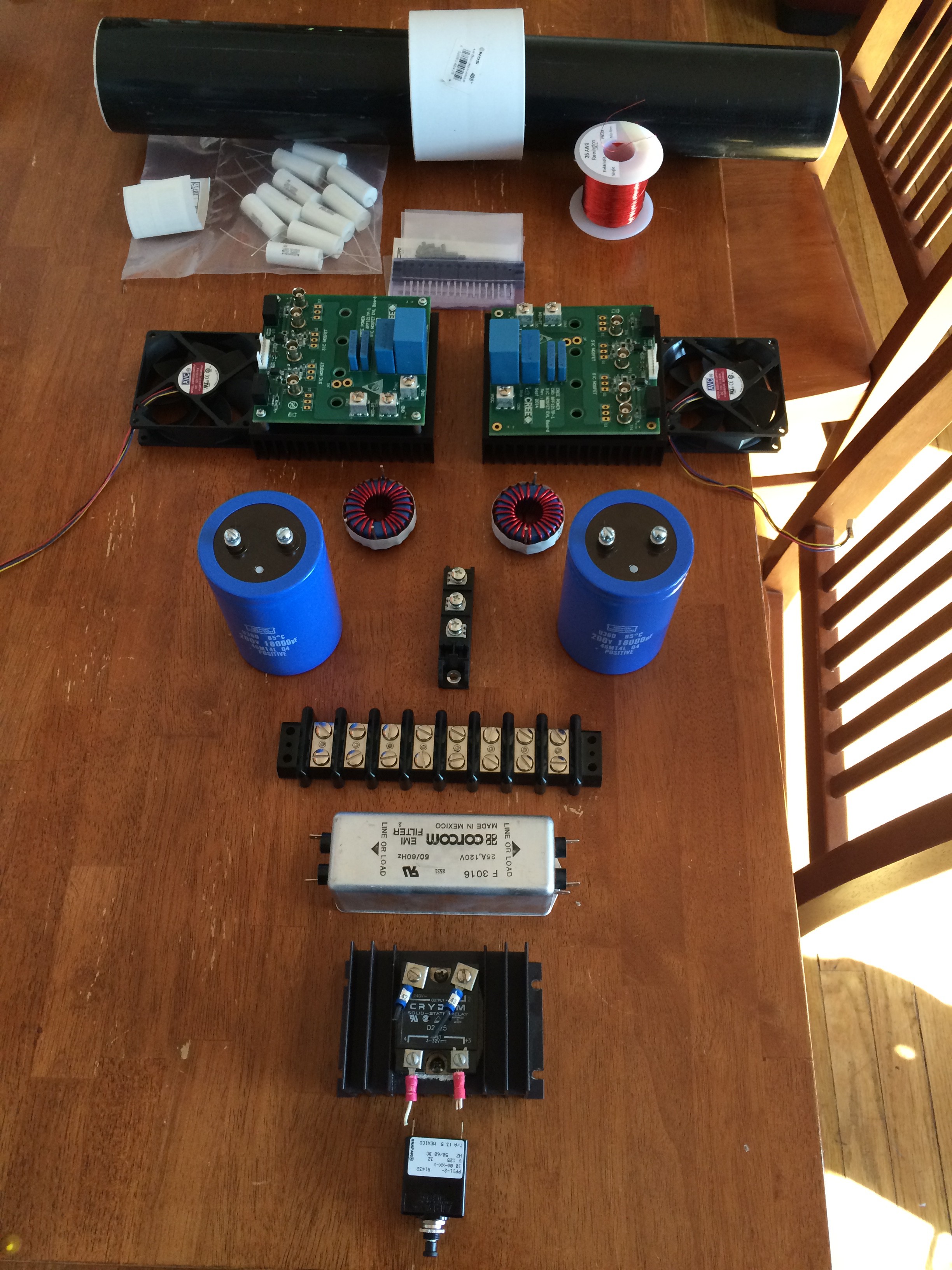
First parts
10/03/2016 at 01:58 • 0 commentsI started out with these components and a vague idea with how they might go together.
![]()
-
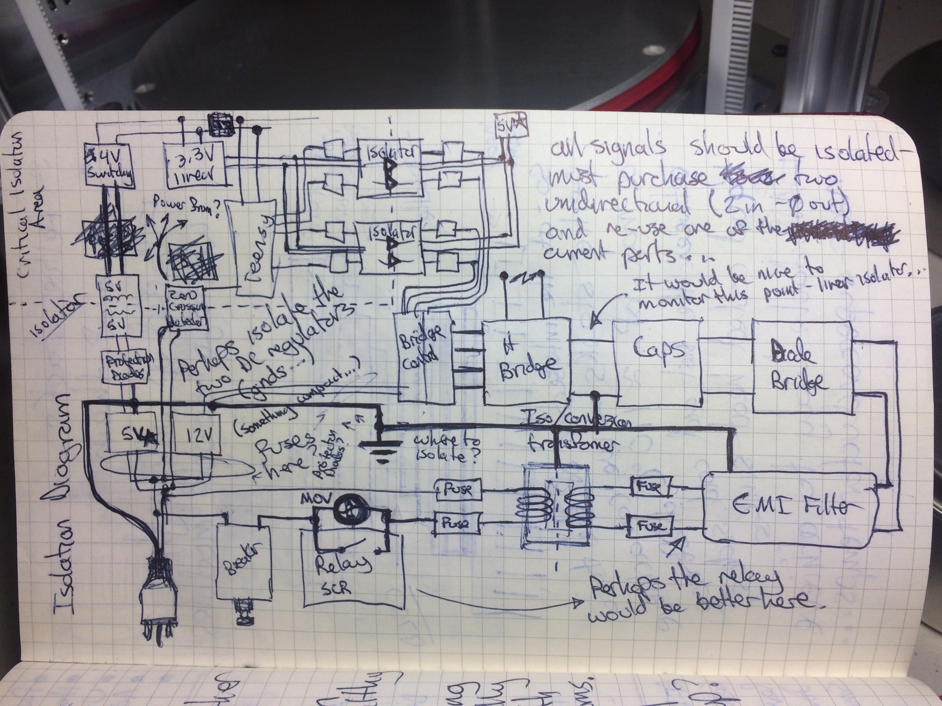
The "Documentation"
10/03/2016 at 01:47 • 0 commentsThis project used nothing resembling a traditional design process - It was a slow evolution that has brought it to this point. I am committed to making the design open and available for other people to take further.
I present the only documentation to date (other than many photos):
![]()
Universal Power Supply
Convert whatever power source is available to the one you need