-
1Build Pedalino model A or model B
Right now the hardware is just a working well prototype. It will be boxed when the hardware will be frozen.
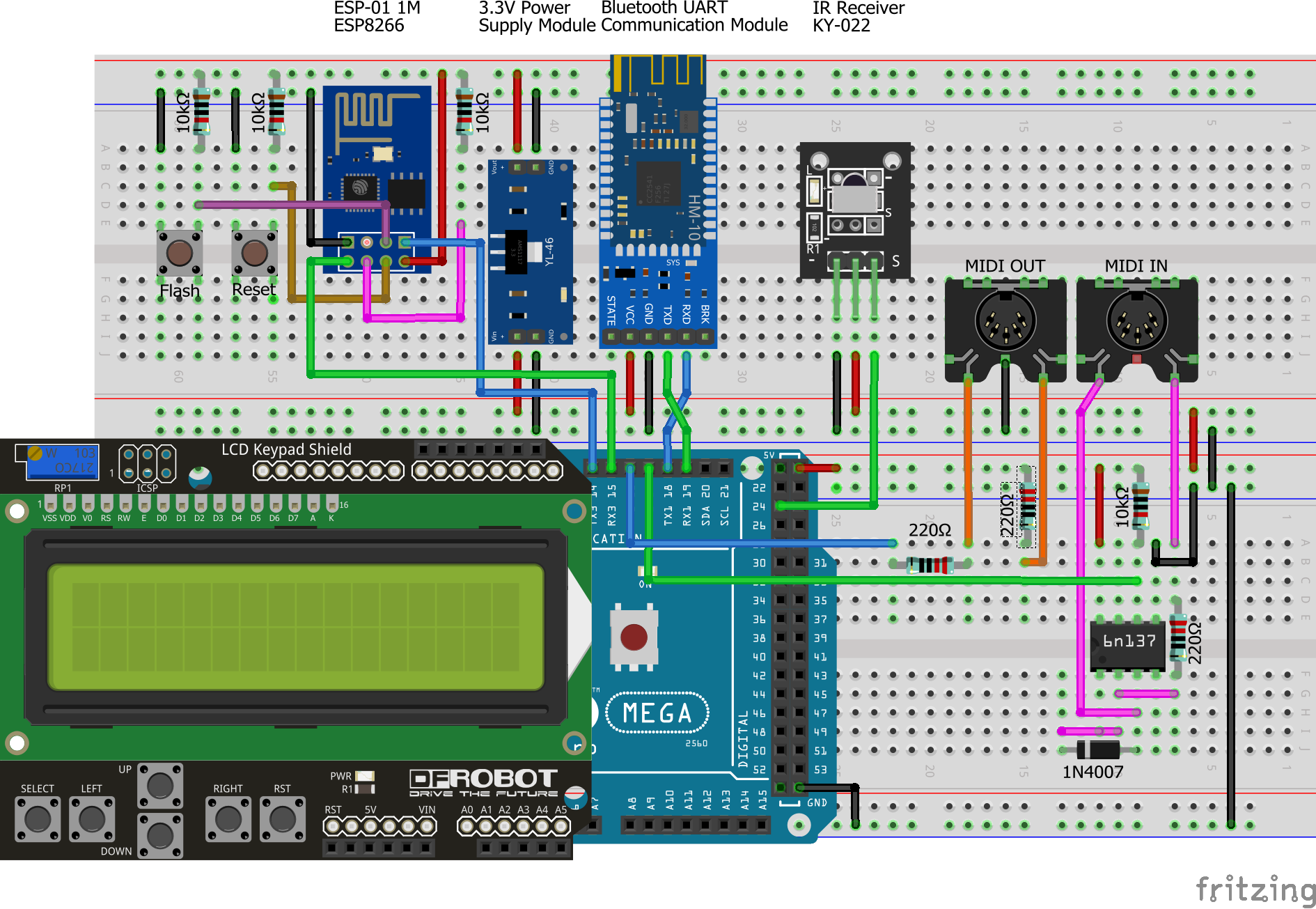
Model A
WiFi only
![]()
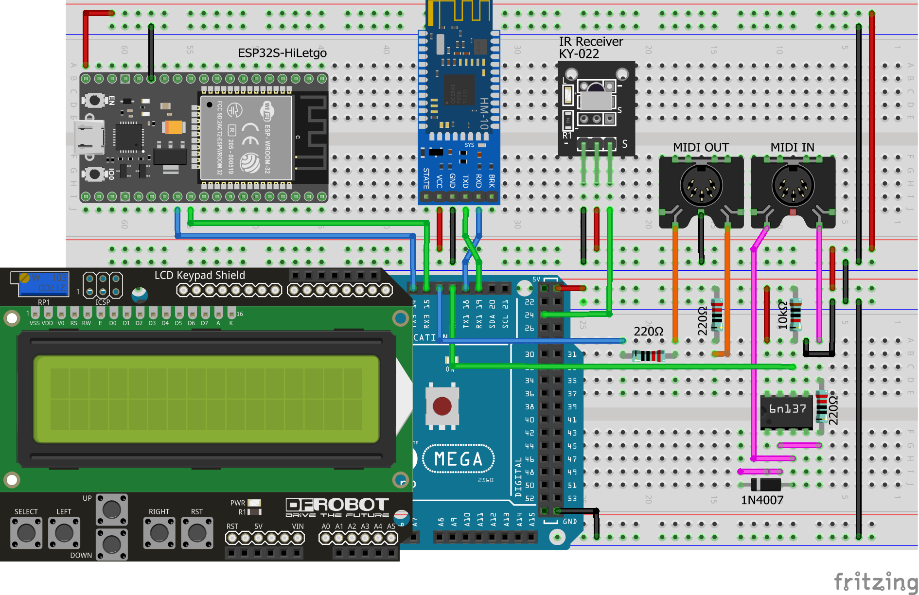
Model B
WiFi and Bluetooth Low Energy (BLE) MIDI
![]()
-
2Firmware upload overview
Pedalino is using 2 boards and 3 microcontrollers. All of them need to be flashed with the right firmware before using Pedalino.
Model Board Microcontroller Firmware Instructions Both Arduino Mega 2560 ATmega2560
ATmega16U2Pedalino
MocoLUFAClick here
Click here and hereA ESP-01S 1M ESP8266 PedalinoESP Click here B DOIT ESP32 DevKit V1 ESP32 PedalinoESP Click here -
3Install build and upload IDE
PlatformIO (recommended)
PlatformIO is the recommended IDE for Pedalino build and upload.
- Install PlatformIO IDE for VSCode
- Run the following commands from View->Command Palette (Ctrl+Shift+P)
- Git: Clone
- You will be asked for the URL of the remote repository (https://github.com/alf45tar/Pedalino) and the parent directory under which to put the local repository.
- PlaftormIO: Build
- Open
platformio.iniand setupload_portaccording to your PC settings - PlatformIO: Upload
That's all folks.
Arduino IDE
Arduino IDE can be used for Pedalino build and upload but it requires more manual steps for board installation and libraries installation.
-
4Flash ESP8266 ESP‐01S WiFi module - MODEL A only
ESP-01S module is usually shipped with AT-Command firmware and flashing a new firmware requires an USB to Serial adapter as outlined here.
Pedalino can upload firmware to ESP-01S without any hardware addition or modification. Pedalino uses Arduino Mega as USB to Serial adapter (bidirectional serial passthrough between Serial and Serial3 ports).
Preliminary operations
- Boot Arduino in serial passthrough mode
- Press and hold RIGHT button on LCD Keypad Shield
- Press and release RST button on LCD Keypad Shield
- Release RIGHT when one or more # sign appear on LCD
- Boot ESP-01S in flash mode
- Press and hold Flash button
- Press and release Reset button
- Release Flash button (the ESP-01S built-in led will flash shortly)
Continue with PlatformIO or Arduino IDE as you prefer.
PlatformIO
- Install PlatformIO IDE for VSCode
- Run the following commands from View->Command Palette (Ctrl+Shift+P)
- Git: Clone
- You will be asked for the URL of the remote repository (https://github.com/alf45tar/Pedalino) and the parent directory under which to put the local repository.
- PlaftormIO: Build
- Open
platformio.iniand setupload_portin[env:esp01_1m]equal to your Arduino COM port - PlatformIO: Upload
Arduino IDE
- Install the current upstream Arduino IDE at the 1.8 level or later. The current version is at the Arduino website
- Start Arduino and open Preferences window
- Enter http://arduino.esp8266.com/stable/package_esp8266com_index.json into Additional Board Manager URLs field. You can add multiple URLs, separating them with commas.
- Open Boards Manager from Tools->Board menu and install esp8266 platform
- Select
Generic ESP8266 Moduleboard from Tools->Board menu after installation - Set the board parameters as follow
![]()
- Load
PedalinoESPsketch - Select Sketch->Upload (Ctrl+U)
Post upload operations
- Reset Arduino Mega
- Reset ESP-01S
USB to Serial adapter mode is required just for the first firmware update. Once connected to WiFi the ESP-01S module can be updated connecting your browser to http://pedalino.local/update.
- Boot Arduino in serial passthrough mode
-
5Flash ATmega16U2 with mocoLUFA
The Arduino Uno and Mega don't have native USB support, so they need extra firmware to be installed to the USB-to-Serial chip (ATmega16U2) in order to work as a MIDI device.
The ATmega16U2 chip on your Arduino board acts as a bridge between the computer's USB port and the main processor's serial port.
Detailed procedure to replace original firmware with mocoLUFA can be found here
-
6mocoLUFA dual boot
mocoLUFA firmware boots in USB MIDI mode by default.
Arduino-Serial mode is required to upload a new sketch into main Arduino ATmega2560 microcontroller.
To enable Arduino-Serial, add a jumper to PIN 4 (MOSI PB2) and PIN6 (GND) on ICSP connector for ATmega16U2. Power on cycle is required to switch the firmware mode.
-
8Pedal Wiring
Pedalino is designed to work with the majority of expression pedals on the market, but there are a few popular pedal types which are incompatible and need to use adapters in order to work with Pedalino.
There is no recognized standard for footswitch and expression pedal inputs. Effects and amp manufacturers use whatever variations are appropriate for their particular application. This can cause problems for the consumer needing to find a footswitch or an expression pedal that will work well with particular devices.
Pedals connector is usually a 1/4" TRS jack. Each stereo TRS socket should be connected as follow.
Pedal TIP
toDigital Pin
RING
to
Analog PinSLEEVE
to
Ground1 23 A0 GND 2 25 A1 GND 3 27 A2 GND 4 29 A3 GND 5 31 A4 GND 6 33 A5 GND 7 35 A6 GND 8 37 A7 GND 9 39 A8 GND 10 41 A9 GND 11 43 A10 GND 12 45 A11 GND 13 47 A12 GND 14 49 A13 GND 15 52 A14 GND 16 53 A15 GND -
9Foot switches
Pedalino supports the following wiring:
Switches
per portConnector Wiring Example 1 Mono 1/4" TS ![TS]()
1 switch between T and S Boss FS-5U
Boss FS-5L2 Stereo 1/4" TRS ![TRS]()
1st switch between T and S
2nd switch between R and SBoss FS-6
Boss FS-73 Stereo 1/4" TRS ![TRS]()
3-Button Schematic Digitech FS3X 5 Stereo 1/4" TRS ![TRS]()
Voltage Ladder LCD Keypad Shield Momentary and latch type switches are supported.
Normally open (NO) and normally closed (NC) is always supported and configurable by software if your foot switch do not have a polarity switch.
-
10Expression pedals
An expression pedal is more or less a pot with a 1/4" TRS jack plug.
Most potentiometers have three connectors; Clockwise, Counter-clockwise, and Wiper. Amazingly, there are multiple different ways these can be wired, all achieving largely the same result, which means yet more variations for expression pedals. The most common expression pedal wiring is to connect the pot to a 1/4″ stereo (TRS) instrument jack as follows:
Standard Connector Wiring Example Roland Stereo 1/4" TRS CW to Sleeve
Wiper to Tip
CCW to RingRoland EV-5
M-Audio EX-P
(switch in "M-Audio")Yamaha Stereo 1/4" TRS CW to Sleeve
Wiper to Ring
CCW to TipYamaha FC7
M-Audio EX-P
(switch in "Other")
Technics SZ-E1/SZ-E2Using a pedal with incompatible wiring can result in limited range, jumping or notch like response, or the pedal just won’t function at all, so make sure you check the requirements.
 alf45tar


Discussions
Become a Hackaday.io Member
Create an account to leave a comment. Already have an account? Log In.