While I don't have such a posh lens, you might enjoy "DIY Photolithography using 1980s Carl Zeiss S-Planar Lens (405nm)" by Huygens Optics in the meantime:
- whatever we as hobbyists can cook up, the ultimate measure of our achievements will be not what we can demonstrate in principle but how well we can catch up with decades of research and commercial development.
And in an necessary act of defining what my project will not be about: it will not be about competing with this product:
I've picked up meditation again - drilling, tapping, filing, sanding and lapping. One tends to get lethargic and lazy just watching youtube machinists do their thing; one of the few activities that get me in the mood is grabbing some stock and make it do things. One day I'll have a shop to call my own again. Meanwhile I occasionally sneak in half an hour at work while some experiment is running, so I appreciate your patience.
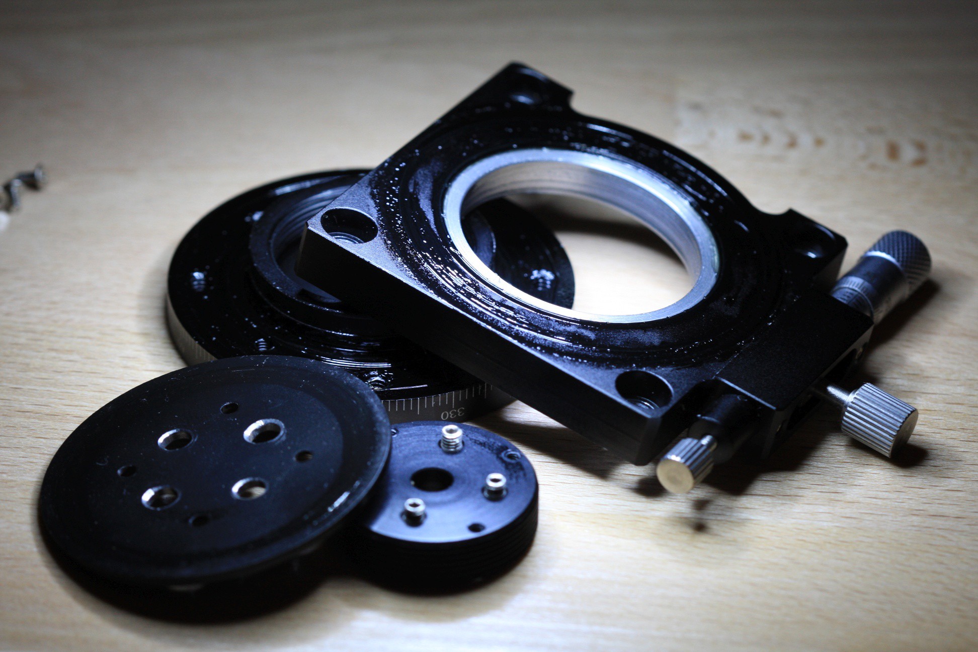
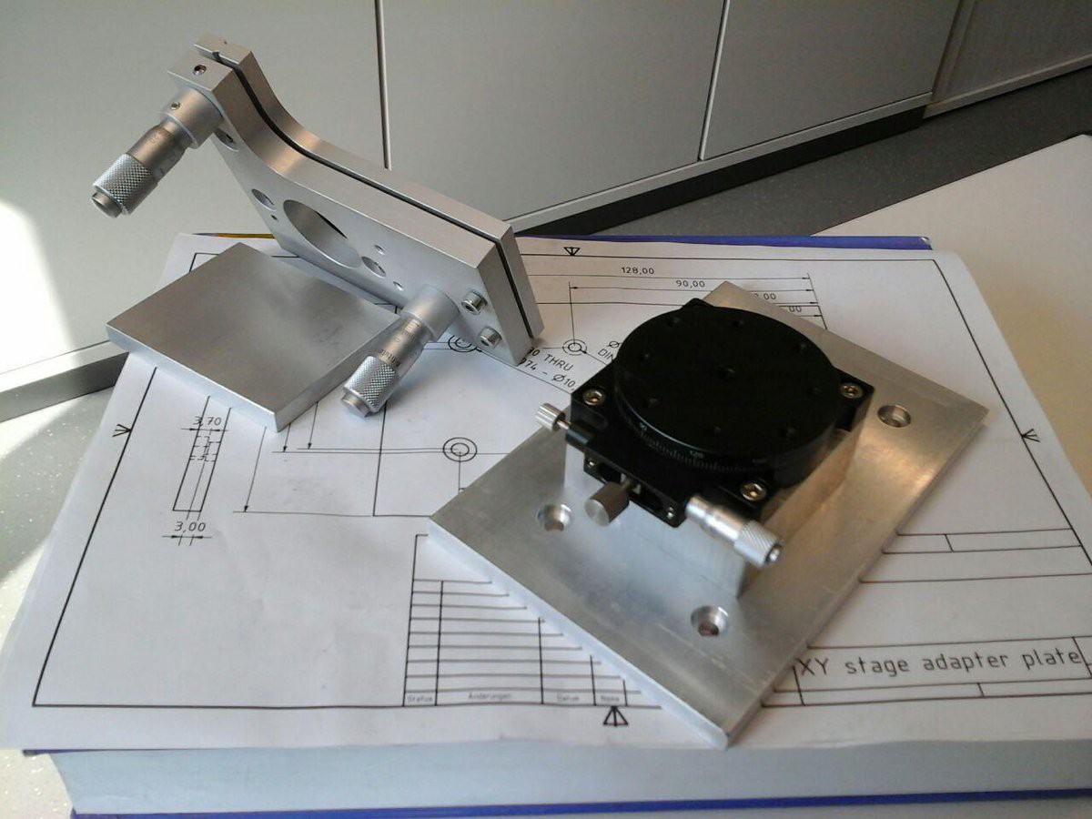
Building the machine could be designed planned and then executed with discipline but.. this is not that. So let's start in an unstructured manner by manufacturing and assembling the mechanical components:
adapter plate to connect motorized XY stage and manual kinematic mount
25mm pedestal for clearance and rigid flat bolting face
adapter plate to mount 2-axis pitch/yaw contraption to the rotating stage
Ok.. I admit I made drawings, telling myself that's so as to not look suspicious in the shop and to reduce the likelyhood of drilling and counterboring a mirrored hole pattern.
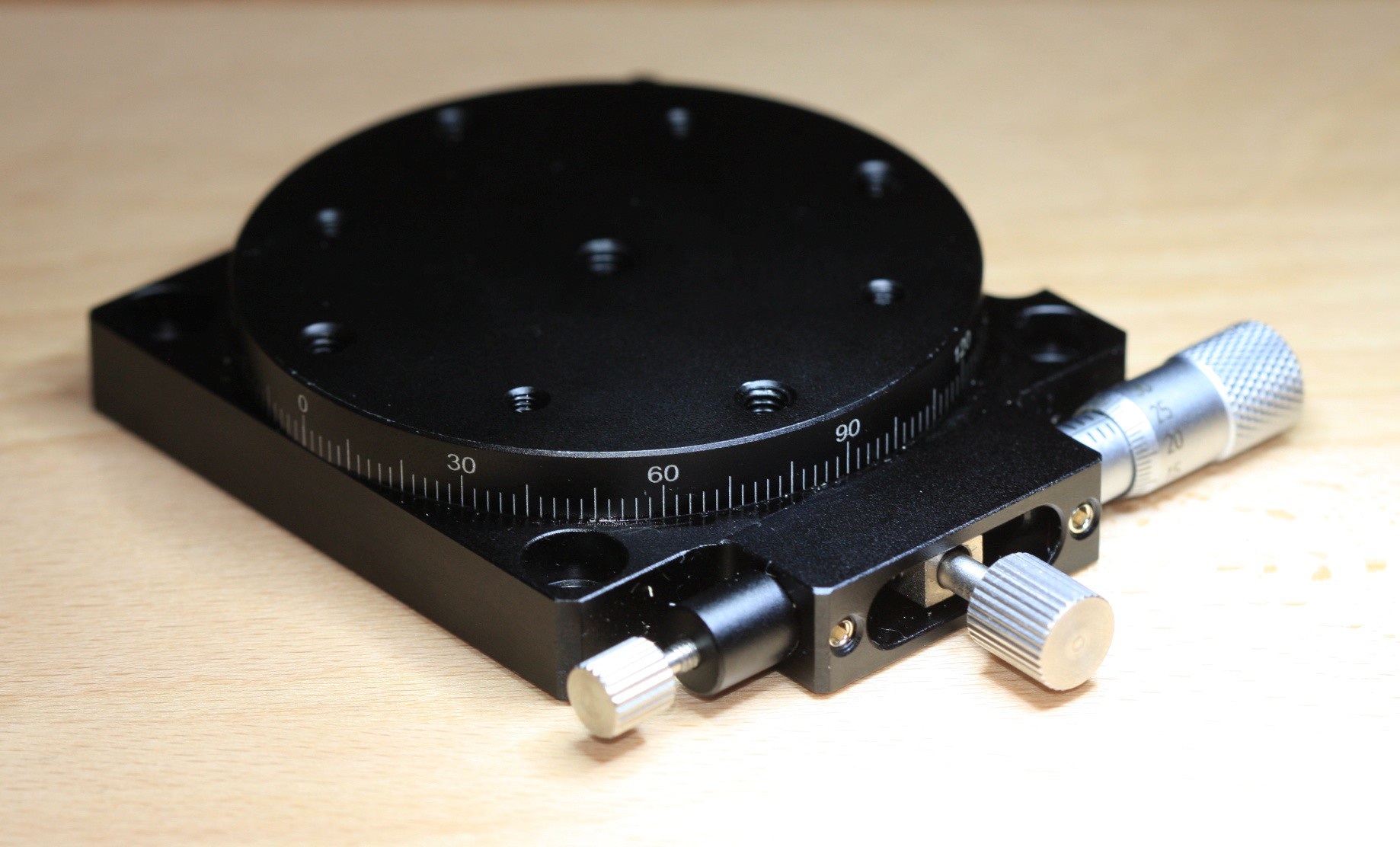
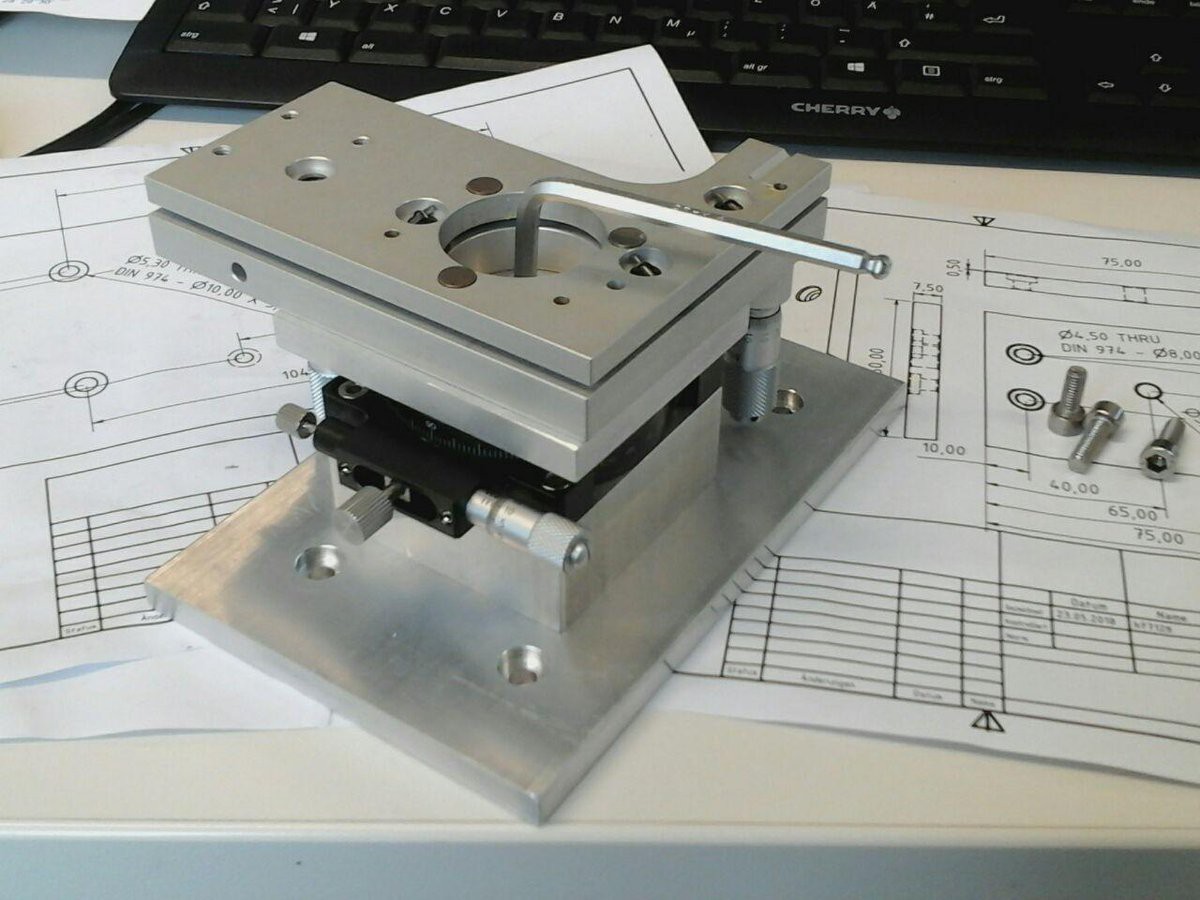
There it is, starring my nemesis, the chinese rip-off stage - raised to a level that establishes some clearance for the micrometer screws. The plates are only 7.5mm thick (no idea why, they ought to be 8mm extrusions) so I couldn't bring myself to do 4.5mm deep counterboring.
The rotating stage doesn't have axial spring preload yet and has to be set manually to minimal play so every minute deformation of the base or turntable results in it seizing up, promting me to spend more time lapping the mating surfaces.
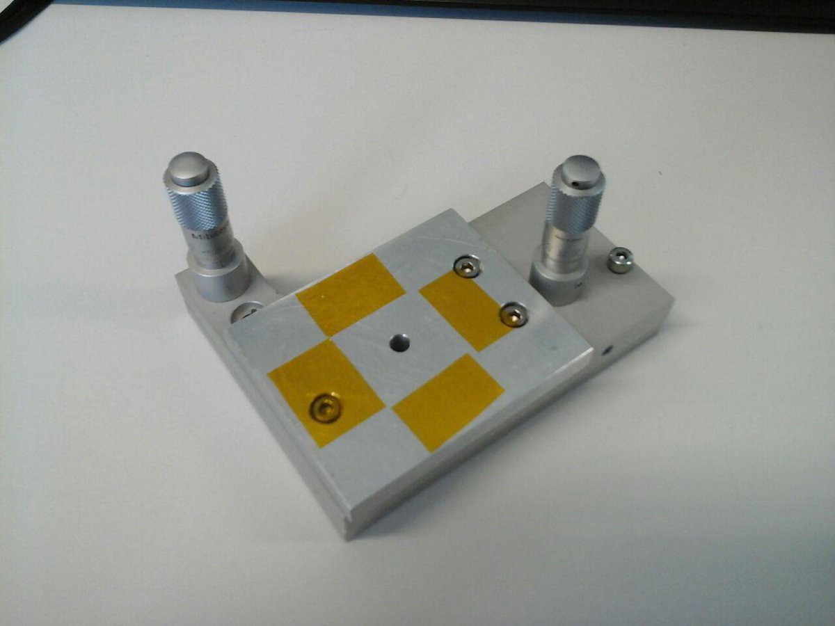
On the micrometer scale everything is a spring element so with the kinematic mount adapter plate done I created an annular pattern of kapton tape stripes, hoping to achieve proper seating without wobble:
The 2-axis tilt/yaw stage now bolts to the rotating mount turntable with a central M5 screw (flat washer + spring washer in between)
Unfortunately the turntable reacts to deformation most unfavorably. The fact that lapping the top plate reduced the issue points to the turntable being very susceptible to z-deformation with an azimuthal dependence.
On top of that it also seems to react to radially varying z-deformation to a lesser degree (convex warpage by pulling the screw upwards against the outer zone).
It is what it is, I guess. Maybe it's telling me I should use the outer M4 threads but they're not accessible with the plate in place, leaving just the central screw. I'm now using it to adjust play :D Mechanical parts have their own way of telling you what's right and what's wrong.
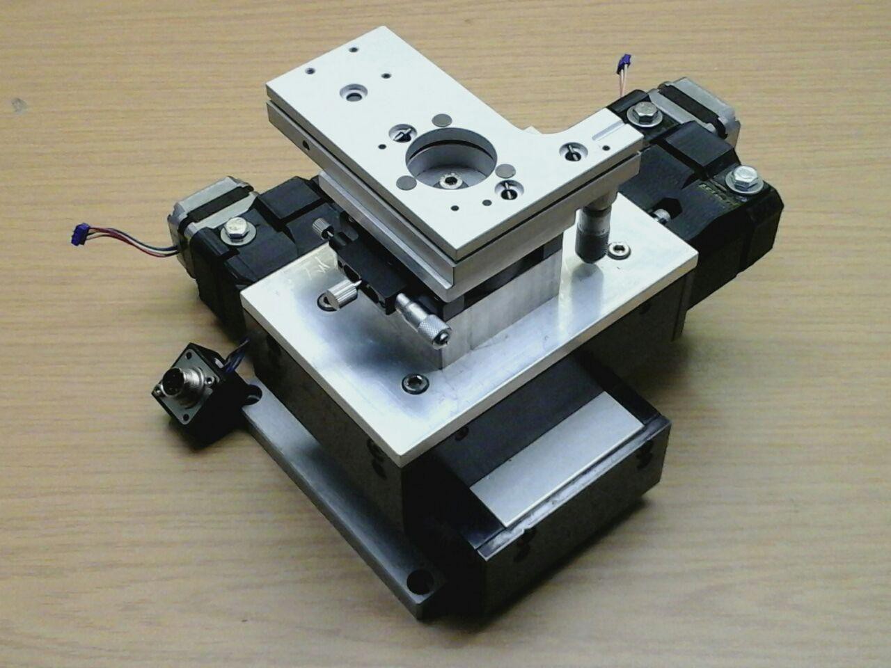
And there's the whole 5-axis stack bolted together:
I'll have to leave the sketchy 3D printed stepper assemblies in place for now. They contain skew gear reductions coupled to the spindles... to be improved once the precision/repeatability test results are in.
See you around.
ps. Why build a 5-axis stage?
Ok, actually there'll be a sixth axis with a piezo actuator (focus in z direction).
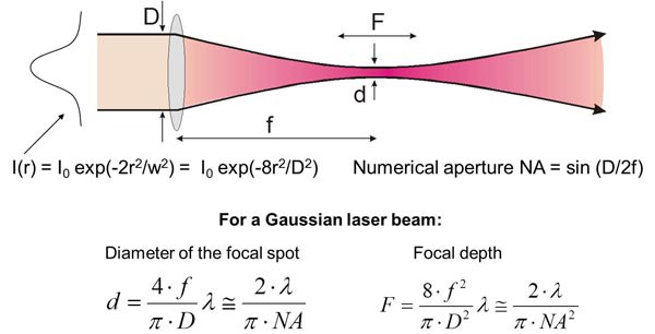
The cartesian axes are obvious. Tilt and yaw have to be adjustable (at least manually) to get the sample surface leveled. For lambda = 400 nm and NA = 0.85 we're looking at a focal depth of about 350 nm which is almost guaranteed to be violated by room temperature driven thermal expansion, vibrations and looking at the setup the wrong way. Wafer pieces are sufficiently flat for their edges to be used as reference features, enabling on-the-fly focus correction but you'll have to start with the object plane nearly level to within a few micrometers across a 10-20 mm wide sample. If there's still some room left for variability within the zone it's going to be consumed by the radially diverging field flatness error.
The motivation for the rotating stage is the need for re-alignment between processing steps, maintaining registration of pixel rows/columns without the need for interpolation and further loss of resolution.
Just hoping I don't have to upgrade all the axes to piezo positioning :)
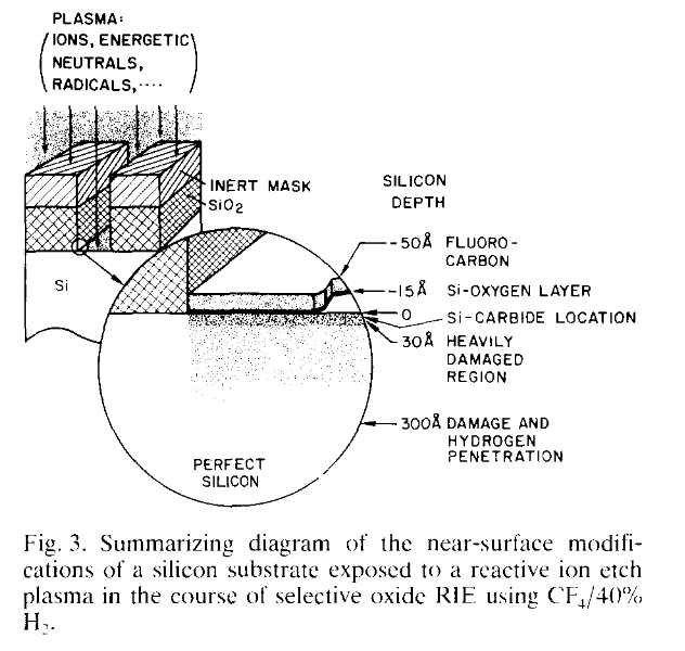
RIE isn't closed-loop and ultimately it's practically impossible (think: SEM + Cl2 gas jet, super slow etch rates, https://aip.scitation.org/doi/abs/10.1063/1.3525587 ) to make plasma etching a maskless process. I could ignore shallow surface damage and ion implantation for my purposes but I like to avoid it if possible. Here's what that looks like:
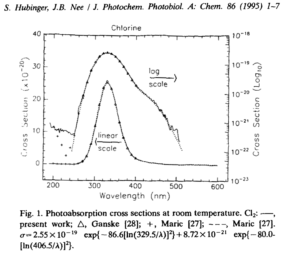
Chlorine on its own or in Ar has a tendency to photo-dissociate at visible wavelengths:
Here's the absorption cross section of Cl2 gas with an onset compatible with 405nm laser diodes and a maximum that's screaming "homebrew TE nitrogen laser":
With a bond dissociation energy of 242.58kJ/mol (2.515 eV/bond) plus (I'm guessing) some additional energy to end up in an excited state the molecular absorption peaks in the UV, capable of causing localized generation of chlorine radicals.
Our goal here is to generate volatile silicon tetrachloride (cue youtube video from NileRed on its conventional synthesis with heated silicon). For this to happen, chlorine radicals must be generated in the vicinity or on the surface of the silicon specimen to be etched and be willing to react with the silicon atoms presented at the wafer surface.
Seriously, Si has to react with Cl. radicals or worse... and there's where the problems start.
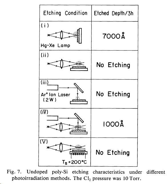
"It was found that n+ poly-Si is etched by chemical reaction with Cl radicals photodissociated in the gas phase, while undoped and p+ poly-Si cannot be etched without irradiation by UV light. The primary effect of the photoirradiation is to produce electrons arising from electron-hole pair generation. The etch rates, etched features and etching products depend strongly on the electron concentration in the conduction band. The experimental results are explained by assuming that electron-attached Cl- ions penetrate into the Si lattice."
Since I'm interested in selective backthinning of p- substrates this is not going to be as easy as swapping the samples holder for a gas tight process chamber and iterating between surface profile measurements and exposure phases to achieve a controlled 3D profile.
It's not as bleak as it might look from the 1985 point of view. in fact, Vakanas 2002 states (also refering to the patent below),
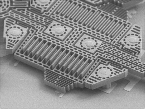
There's a project which matches the capabilities of VarioEdit:
"Intel plans to ship 10 nm integrated circuits in 2017[3], and TSMC plans to offer 7 nm chips in 2017. [4] Manufacturing at these technology nodes will require high-speed and high-resolution image acquisition for process verification and failure analysis. The RAVEN program is focused on developing an analysis tool capable of imaging minimum size circuit features on a silicon integrated circuit chip."
"Officials of the U.S. Air Force Research Laboratory at Wright-Patterson Air Force Base, Ohio, announced a $23.8 million contract to Varioscale earlier this month for the Rapid Analysis of Various Emerging Nanoelectronics (RAVEN) project."
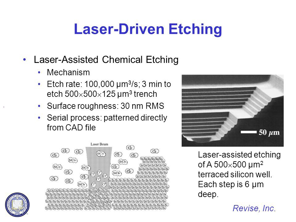
ok, enough with the tinfoil hat stuff, back to facts from the 2002 Vakanas paper: Seeing the wavelengths and power densities I'm really not so sure anymore ;-) But now you've seen the name and recognize it on this lecture slide.
Note how the 514nm (guess: Ar* laser) photon energy is below the 493nm resulting in photodissociation of chlorine... Wonder what a few 455nm diodes could do instead, avoiding the bulky and inefficient Ar* light source.
I doubt the process relies upon heating the Si locally until the reaction to SiCl4 just takes place since it is claimed that the properties of active circuitry are not changed even when gainig backside access up to 2-3 micrometers away from transistor structures. Excessive heating would drive dopant diffusion and break functionality. Heating to 150-250°C might be beneficial though, if only for chlorine or chloride diffusion into Si.
ps. as for the electron generation / injection ... I suspect Lenard tubes are a really bad idea :)
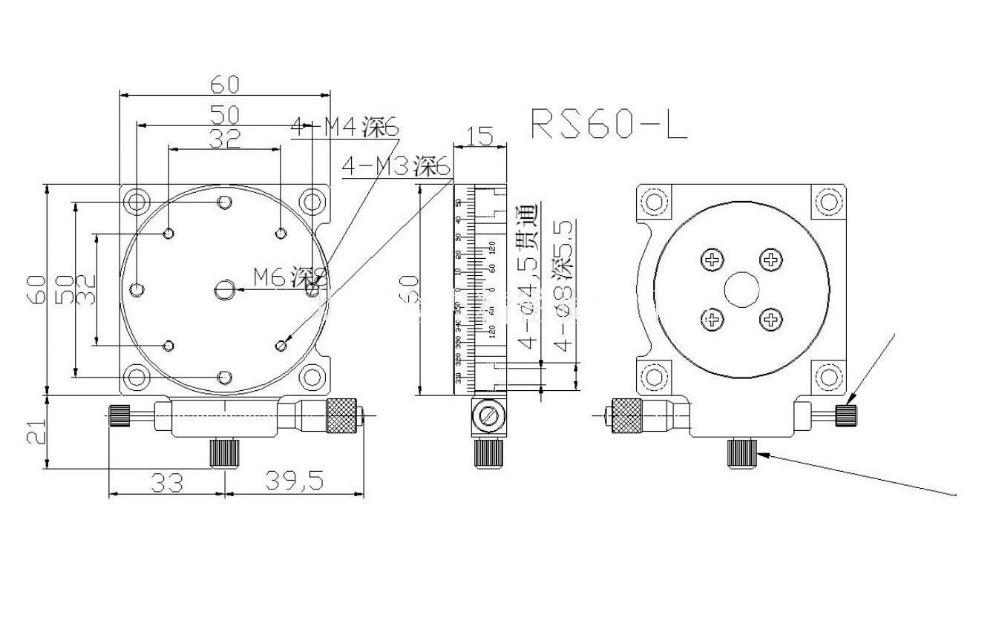
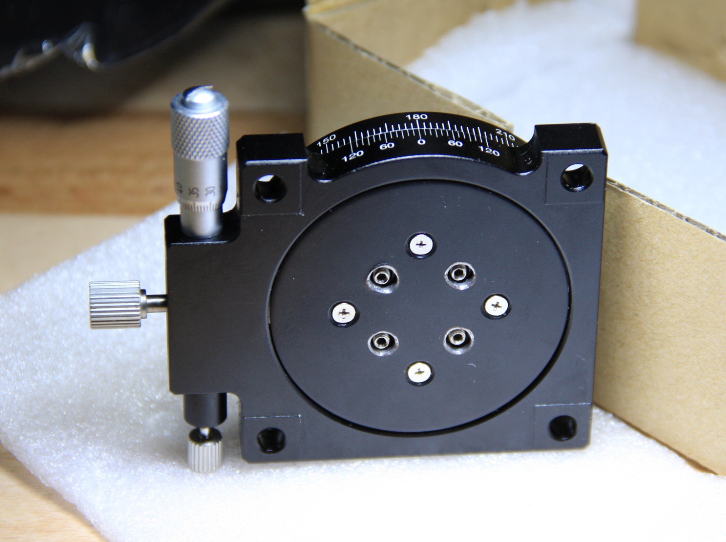
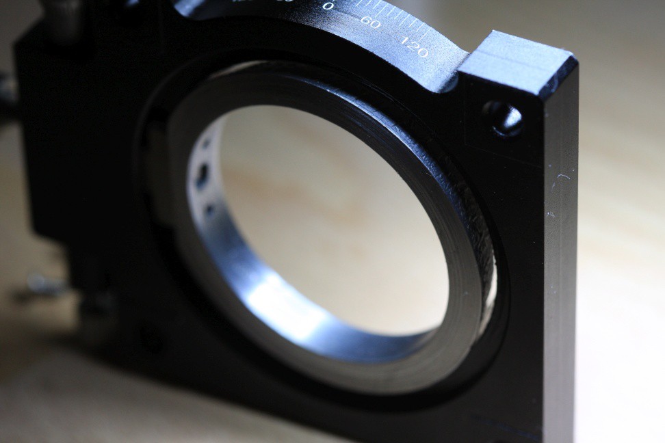
Let's start with the few things that are actually right with this interpretation of a rotating stage. There are dimensional drawings:
While the micrometer adjuster is tiny and too close to the plate, it works ok. It even has a ball nose as you'd expect.
And that's about where it ends with the rainbows and the unicorns.
The thumb screws are flimsy and their fit is horrible. Since at least the center one that locks the precision rotator to the turntable seems to be turned on a lathe I assume it just came out way undersize.
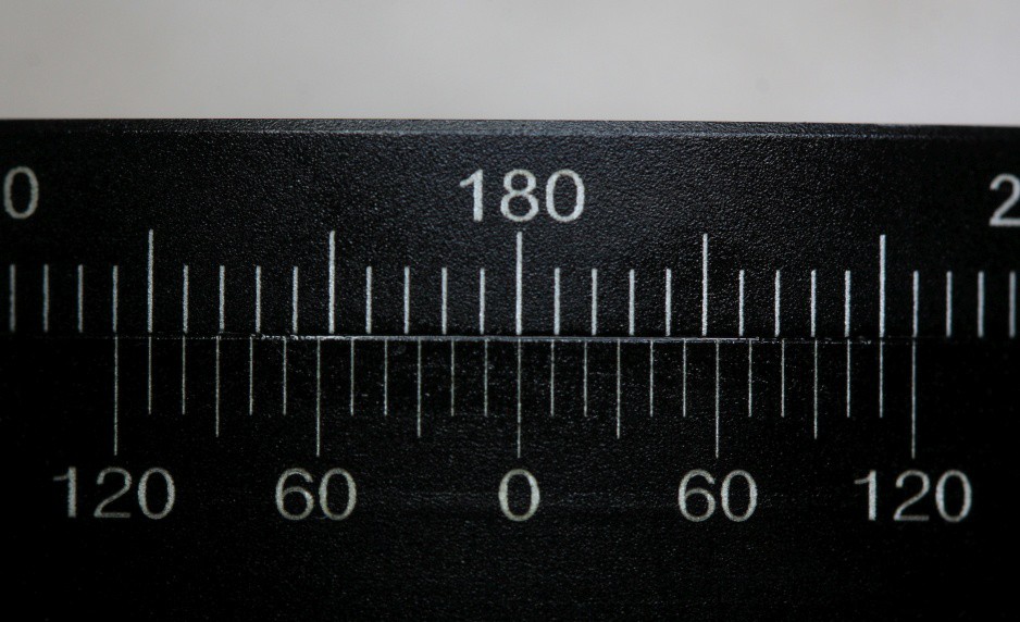
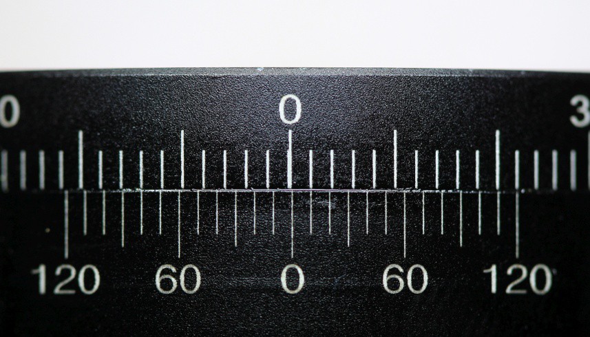
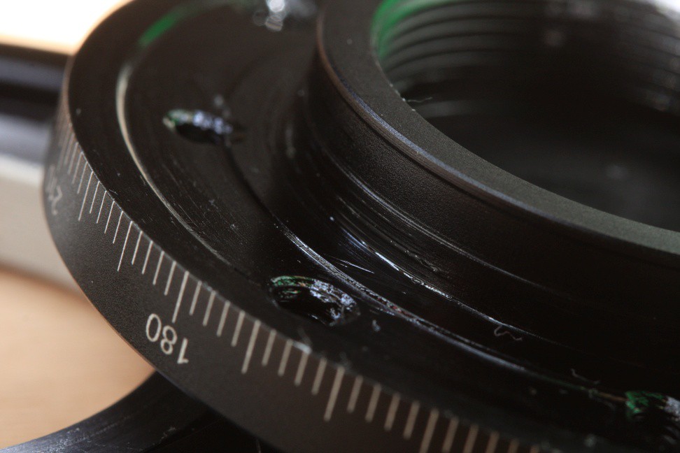
Next obvious thing: the top hole pattern is off by 5-ish degrees. While this might be deliberate, you'll have to create a rotated hole pattern if you want to bolt something to it that lines up with the scale. Plus I'm not sure if the scale is just scribed in a random orientation and every part is different. Good luck with that.
But don't worry about the scale marks. You won't be using them anyway.
Seems ok?
No.. it's not. While this was supposed to come out looking like a vernier scale I wouldn't know where to put the zero on that thing.
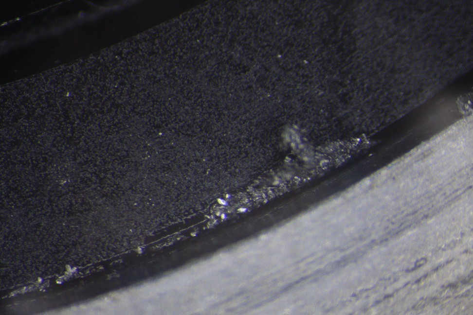
While these issues are just superficial, let's have a look at how "precision bearing" is being interpreted. And nothing speaks precision like these butchered, rusted countersinks:
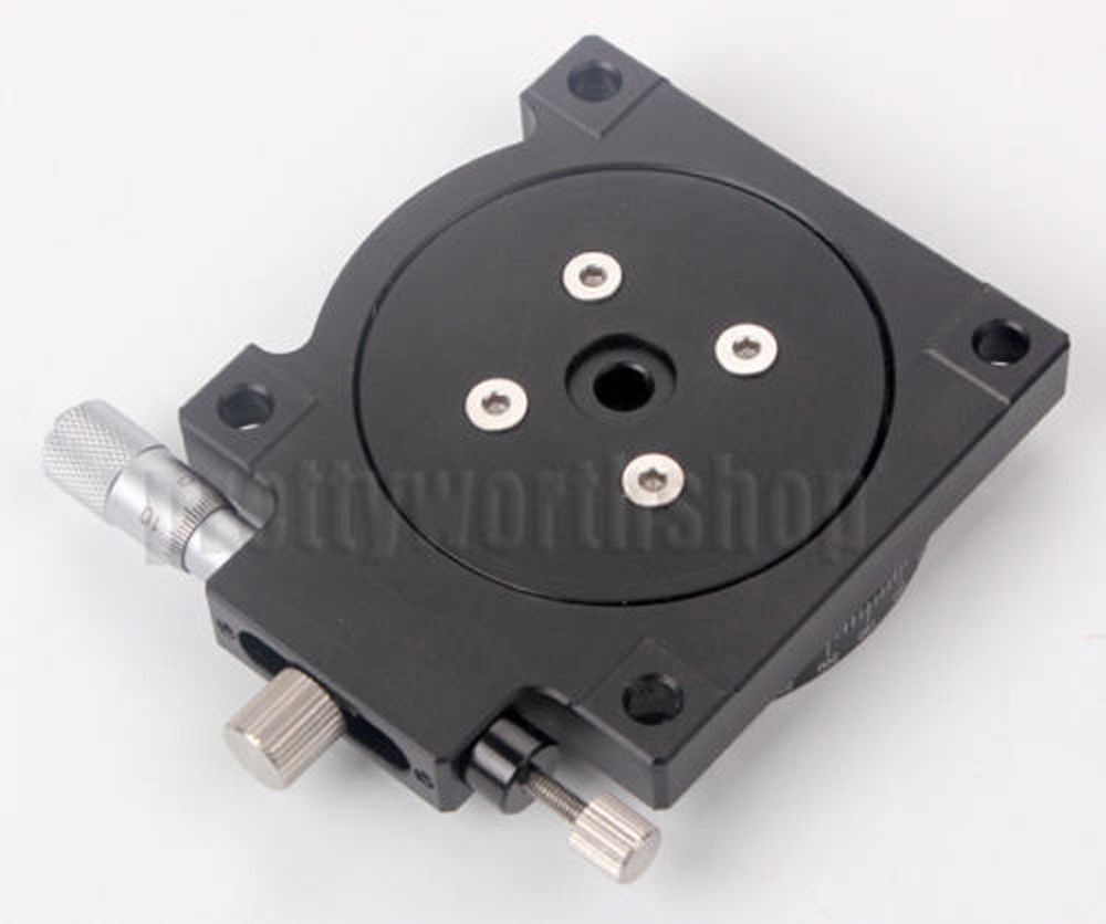
Let's compare this to the auction picture:
Something undoubtedly changed anlong the way. But wait, there is more. I'm suspecting that what makes this thing have a precision feel is nothing but a generous helping of this glorious stuff (oh so Very Press):
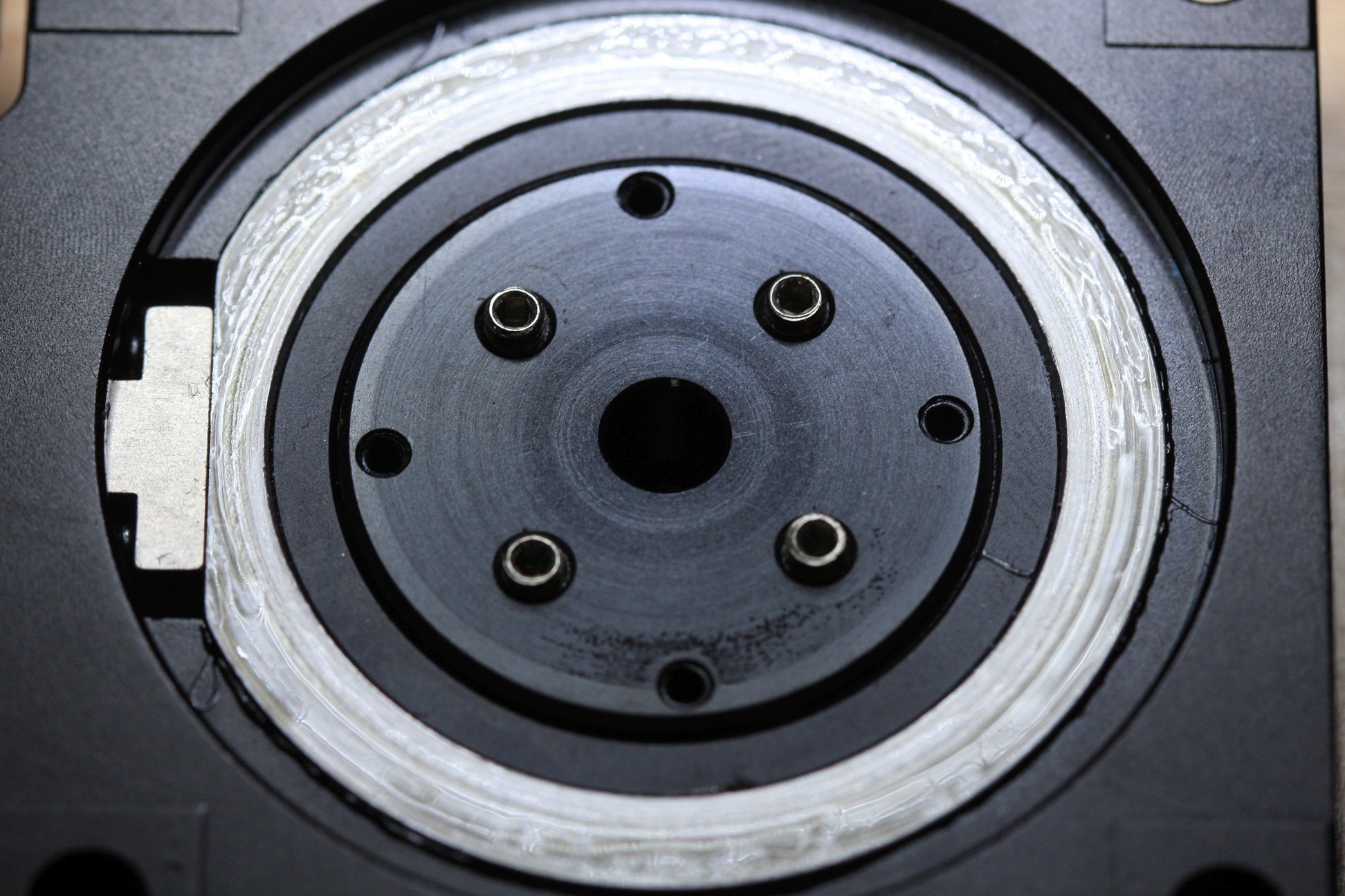
Undoing the four PH0 screws makes the steel plate come off.
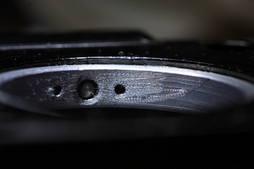
This doesn't look much like a precision bearing, does it? It may be a "bearing surface" but it sure isn't lapped and neither is it precision (such tool marks are usually 10+ µm in roughness). Then again, why would it need to be lapped if it rubs against the paint of the steel disc, getting loaded with paint particles during use. The center is threaded and four set screws lock it in place, also annoyingly backing off the back disc as you tighten them which makes the assembly loose once more. Fun fact: the T-shaped part attached to the ring is a powder metal part. Maybe that's why the thread is so sloppy. Back to topic. Below you can see the bottom reference surface of the turntable.
I then took the rest of it apart, revealing the whole mess. I'm not sure if I'd call the aluminium anodized judging by how it chips away at the edges. Here's the last positive thing of note: they actually relieved the contact surface. I didn't measure the inside and outside residual ring heights but I'm guessing it'll want to make contact on the inner one as well. *sigh*
The conical steel? ring inside is slightly raised and pivots a bit and when the center thumb screw is tightened, it rotates against the main body to translate the 3-4mm of usable travel of the adjuster into some +/-2° of fine rotation while the turntable still slides on the face of the main plate.
The cone also allows it to self adjust or compensate for coplanarity error of the whole clamped stack as the stage rotates (doesn't work in practice once you adjust for zero backlash). The plate looks like it had already been mounted to something so my guess is that it's being screwed onto a face plate and subsequently the conical inner surface is turned to match the ring.
Now whitness the craftsmanship.
Uh yeah, dremel away at those burrs. And that's no MoS2 or graphite grease, mind you. That's aluminium particles mixed with grease for some extra crunch.
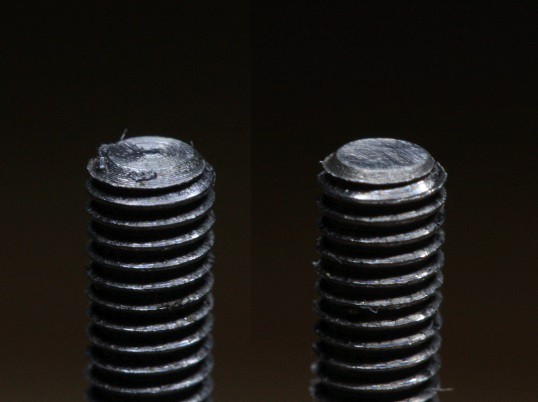
I sanded and cleaned the center thumbscrew so it wouldn't bite into the aluminium surface of the turntable.
After that I wiped down all the grit and junk with ethanol, then with some light oil and finally applied a controlled amount of fresh grease and put everything back together. Getting the bottom steel plate tightened to just the right amount so it comes out convincingly after the setscrews are finger tightened again is not easy.
With everything back together I'm going to leave it like that for now. I'm hoping static friction will hold the turntable in place so it doesn't move around on me during operation when all mechanical adjustments are made.
Setting the rotation will need to be the first step in the alignment procedure and cumulative tilt errors will be compensated with the 2-axis kinematic mount not shown here. The height will be left to the objective z stage and offsets are irrelevant thanks to the XY stage.
Conclusion? Next time I'll grudgingly fork out $100+ for a quality surplus part and move on.
ps.: Constructive Citicism:
It is what it is. The base plate top - to - turntable bottom bearing contact is the main locating feature in this assembly. The conical ring holds the turntable down and locates it laterally, so clean surfaces and a consistent preload are key.
* take the whole thing apart, degrease and inspect. Stone raised burrs if present, don't sand the aluminium bearing surface (alumina or carbide particles will get embedded into soft metals and cause scuffing)
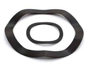
* add a wave spring washer between the inner ring and the bottom plate when you put it back together. The threaded stud has approx. 30mm diameter, the conical ring comes in at 45mm and the pocket is around 50mm in diameter. Get multiple thin spring washers with >=32mm ID and < 50mm OD - they must contact the ring which is between ~35 and 45mm . The washers can be stacked to empirically determine the ideal preload. You don't want more than 10 Newton and there are only a few tenths of a mm to work with anyway. Keep in mind that this preload must not translate into friction larger than the torque caused by the spring opposing the micrometer or the turntable will get stuck, messing up the fine adjustment capability.
 helge
helge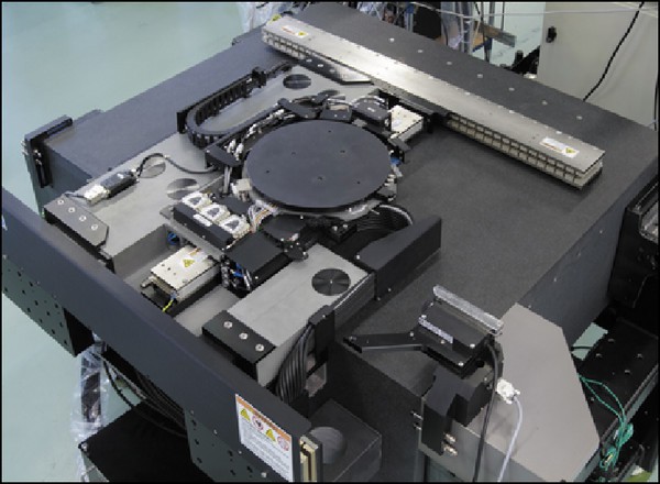

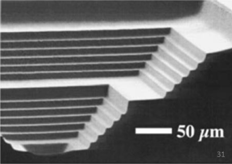
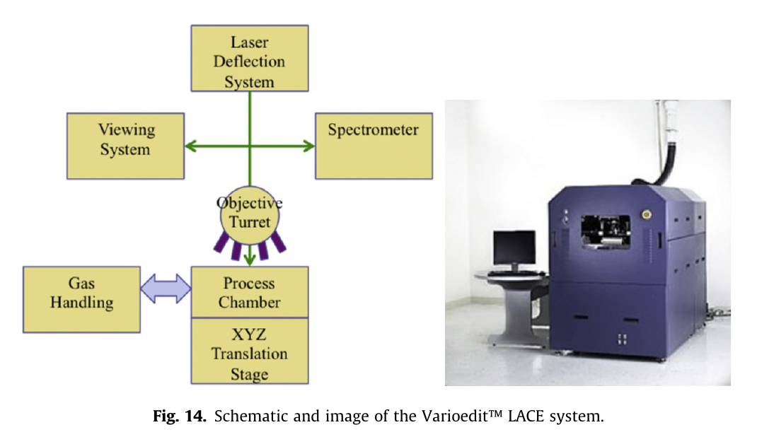 there are a few more juicy pictures of macroscopic terraces etched into thick wafers, so this really is a thing. Unfortunately there only seem to be one or two pictures showing the machine so it's doubtful anyone out there really owns and operates it (or they're not allowed to talk about it, exception:
 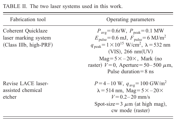 Seeing the wavelengths and power densities I'm really not so sure anymore ;-)