ottoragam
-
Cost analysis part 1
06/03/2018 at 21:52 • 0 commentsAfter having selected nearly every part needed to buld the automatic feeders, I decided to do a cost analysis to make sure I'm still in the right path with the project.
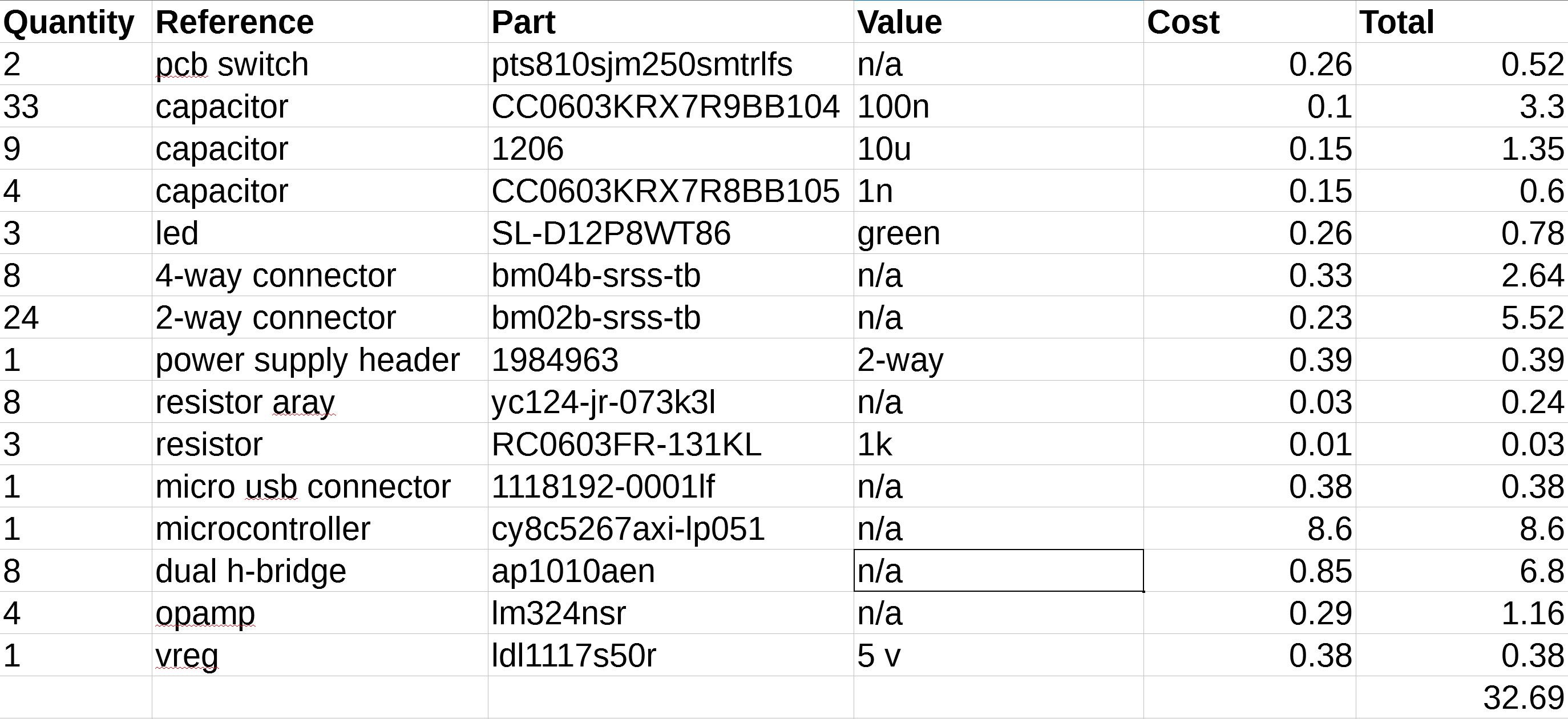
Here's the BOM for one 8 channel feeder controller:
![]()
All the prices were taken form authorized electronics distributors, and I estimate the feeder PCB to cost about $3 USD.
The motors needed for the feeder are about $1.5 each in single quantities, and each feeder uses about 75 grams of PLA filament. The laser cut tape sprocket adds another $5. Taking all this into account, the mechanical parts for a single feeder amount to $9.5.
In total, we are now at $14 USD. I still need to add the cost for the cables and the final quadrature encoder electronics and a few fasteners, but I feel that a cost of less than $20 in parts is very attainable. Also, this analysis does not take into account the volume pricing of any part, meaning that when fabricated en masse the cost will be even better.
-
System architechture
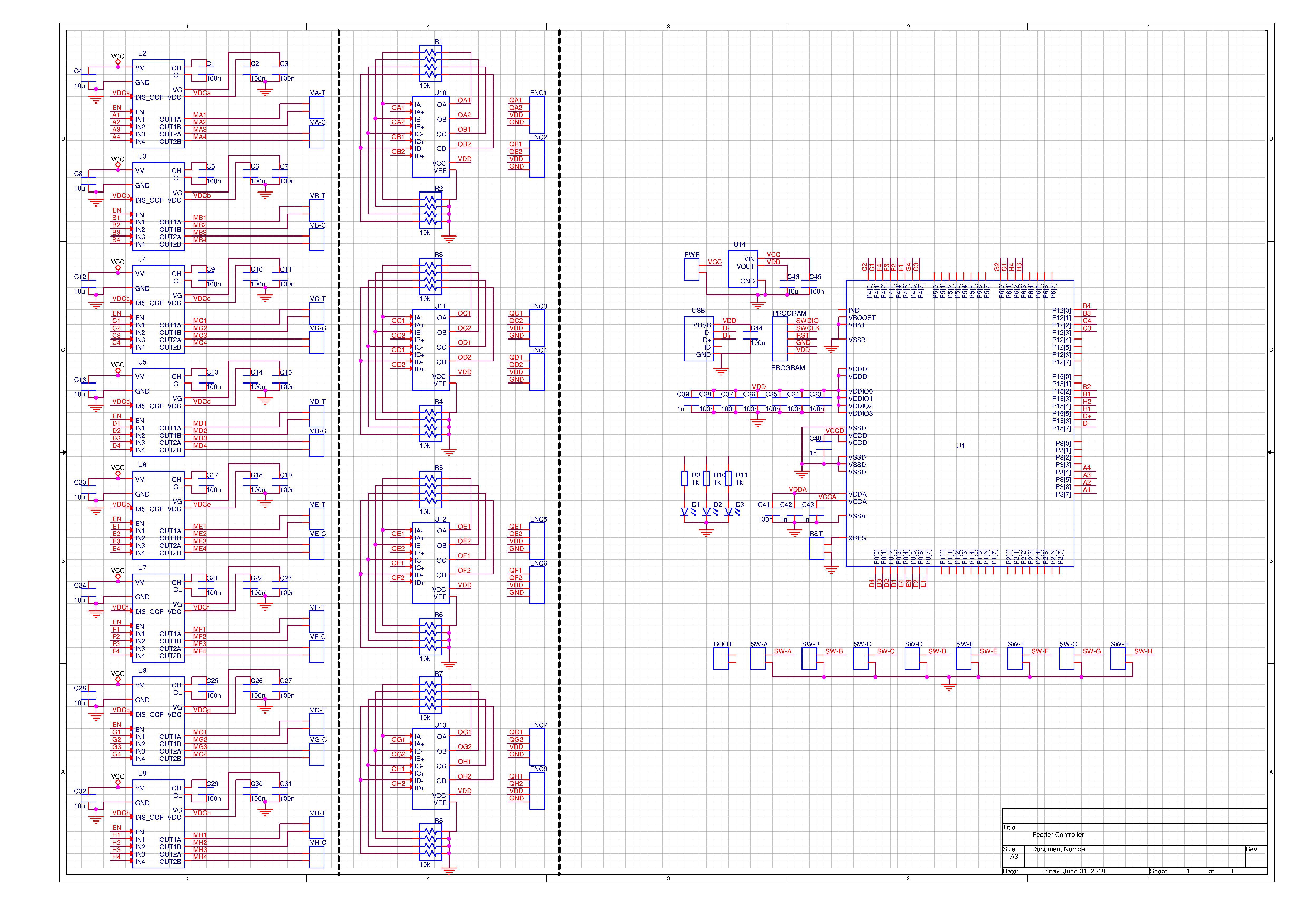
06/02/2018 at 00:31 • 0 commentsI started working on the control board for the automatic feeders last week. The electrical schematic is almost complete, and the board routing is going well:
![]()
You can get a PDF copy of the schematic via Github (https://github.com/ottoragam/Kinnow). There you can also get the STL models of the feeder parts.
The board is going to support 8 automatic feeders. I chose a PSoC5200 microcontroller. It is a Cortex ME3 unit with integrated programmable logic. The programmable logic is crucial to perform the quadrature decoding of 8 optical encoders and to generate the 32 pwm signals needed to drive the 16 brushed motors. It will have a USB bootloader to make things easier for the final user.
I selected the AP1010AEN motor driver for it's compactness and low cost. It is a dual H-bridge chip capable of driving motors up to 18V and 350 mA when using both channles.
There will be four 4-channel LM324 opamps to amplify the signal coming from the phototransistos used in the quadrature encoder sensors.
![]()
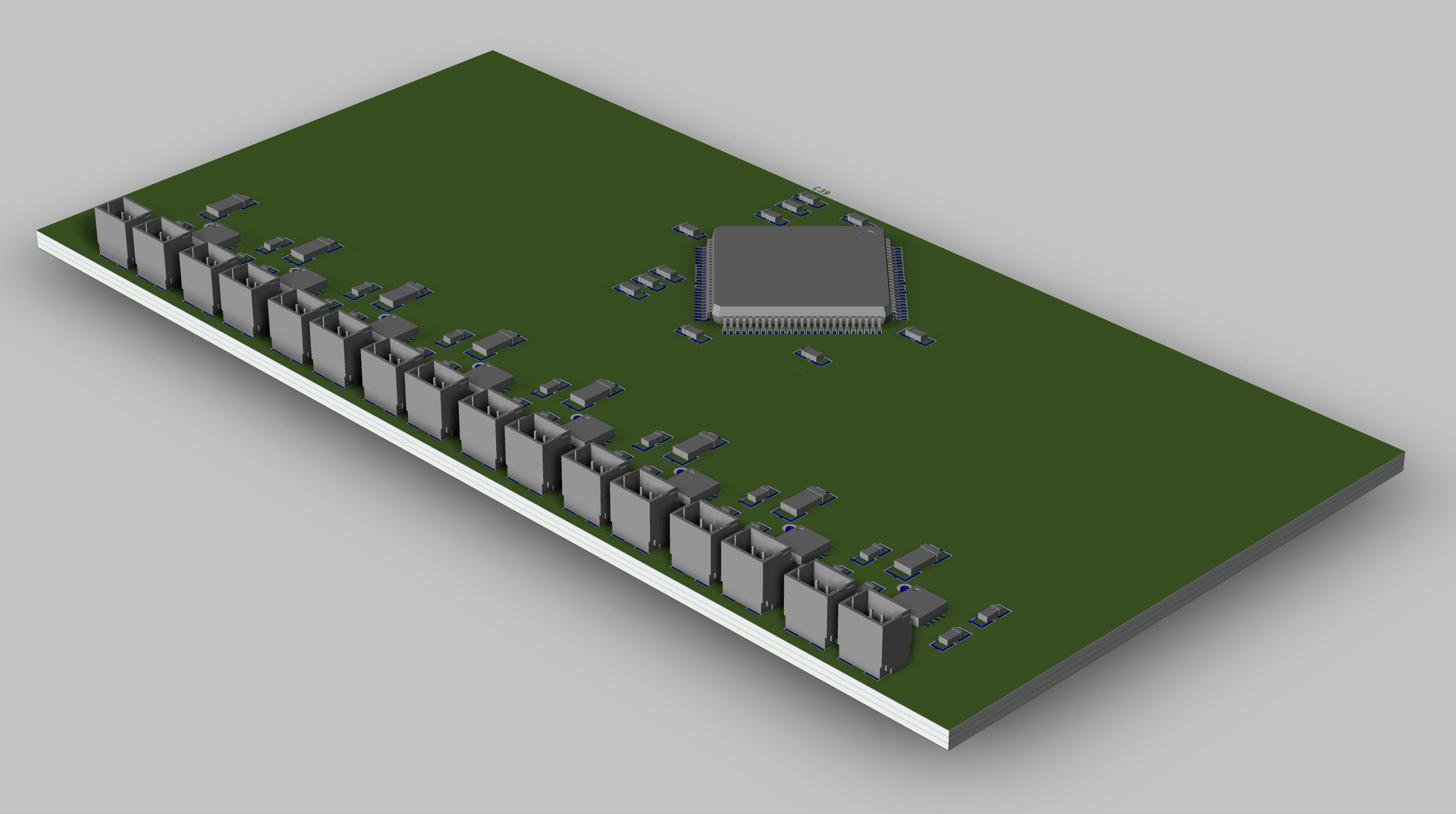
The boad measures 50x100 mm and it uses JST-SH connectors (1 mm pitch) in order to fit everything in a reasonable space. The controller is intended to work with a 6 to 12 V power supply, and it features an onboard voltage regulator for the logic, allowing for single supply operation.
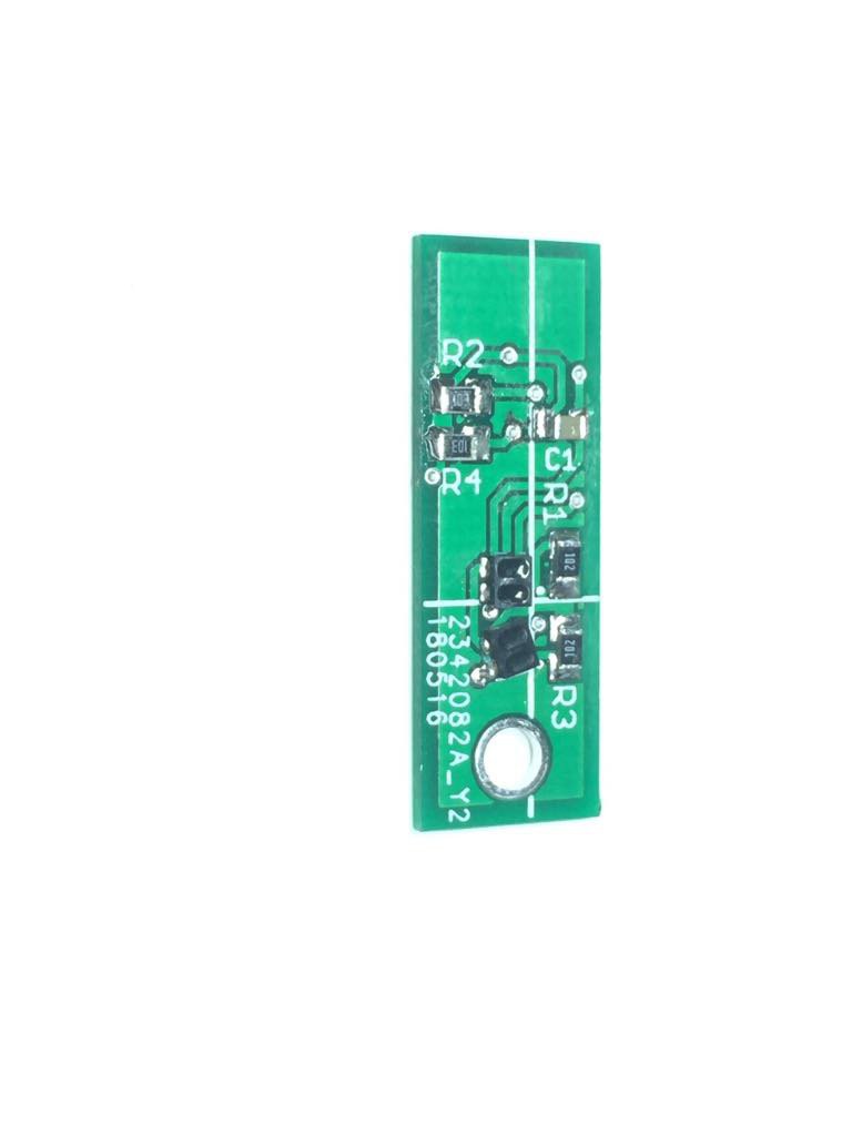
Also, last week I got the boards for the quadrature encoder sensor. I'm currently performing some test, and I'll publish the respective findings once I get a reliable quadrature signal.![]()
-
Parts feeder works!
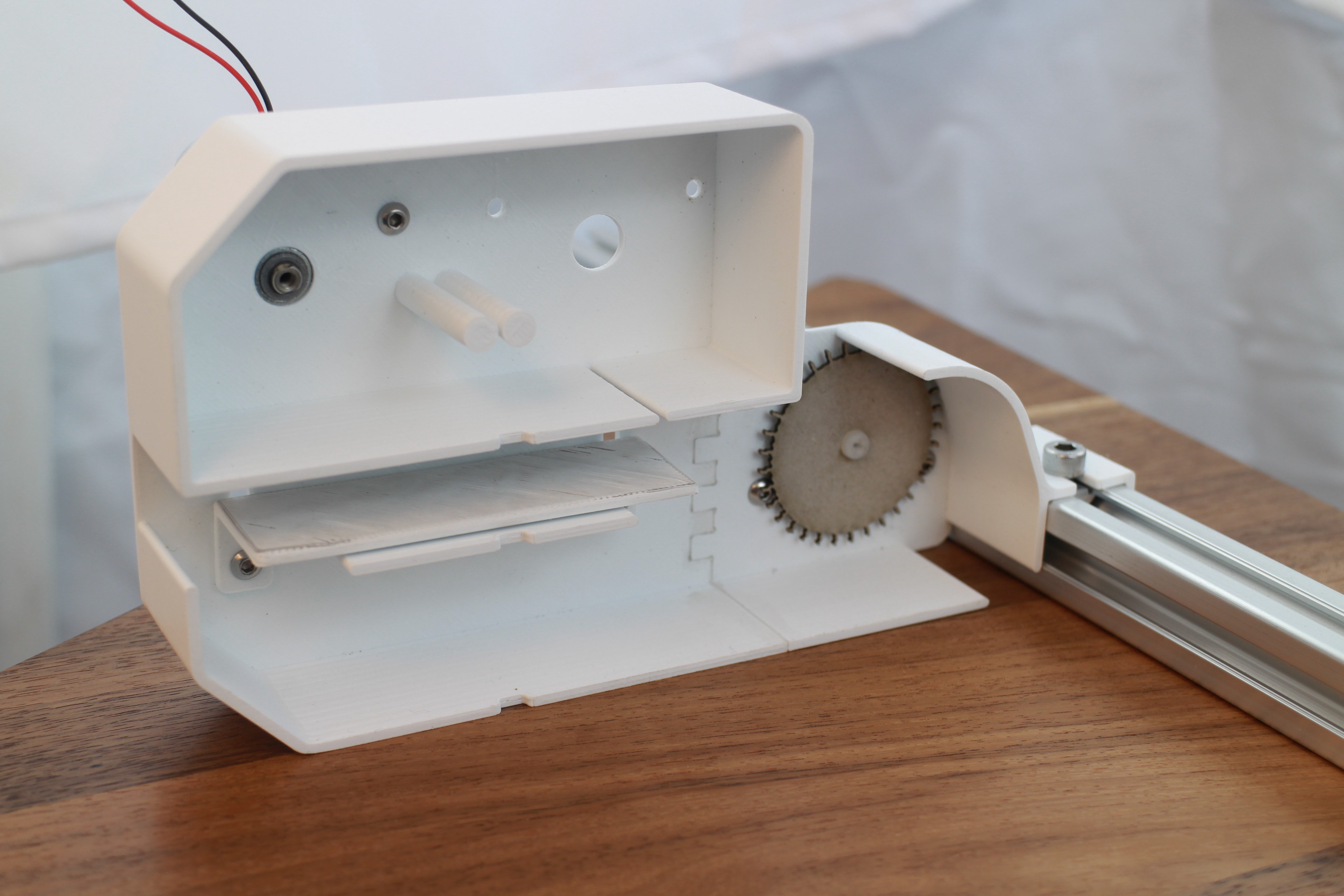
05/20/2018 at 22:18 • 0 commentsThe parts feeder features are:
- Stackable cartridge design (it uses 30mm per cartridge)
- Cartridge is mountable in a 2020 extrusion bar
- Adjustable tape thickness, for maximum compatibility
- Support for up to 8 meters of cover tape winding
![]()
Here's a video of the feeder moving the tape back and forth:
-
Choosing components
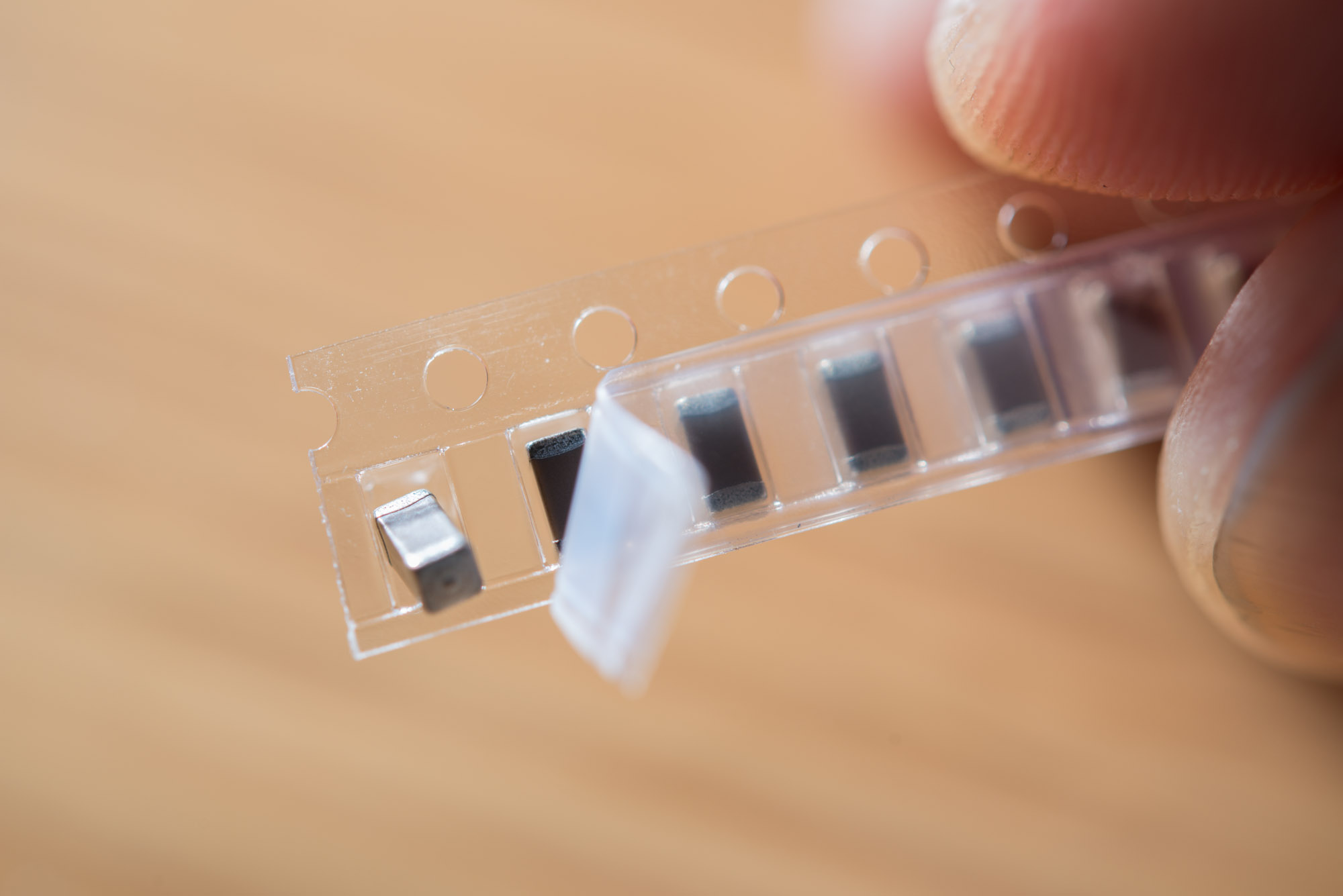
05/07/2018 at 03:51 • 0 commentsMany SMD parts are provided by their manufacturers on an embossed plastic or paper tape. A thin, transparent cover tape is placed on top of the carrier tape to avoid the components from falling out. The carrier tape has a fixed spacing hole pattern on one side (or both, if the tape is sufficiently wide). Normally, a sprocket wheel meshes with these holes and is spun to advance the tape.
![]()
SMD capacitors in tape & reel packaging by Filip Wahlberg. Licensed under the Creative Commons Attribution-Share Alike 4.0 International license.The purpose of an automatic tape feeder is to move a new component to a known and fixed location each time the pick and place machine needs to place the part in question on the PCB. This feeder design uses a sprocket with a DC motor to accomplish this.
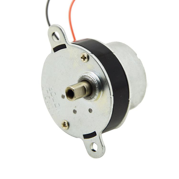
Some existing feeder designs use a small gearmotor and a worm gear to reduce the overall thickness of the feeder. I opted to use a not so short gearmotor that doesn't require extra mechanical parts, with a hollow, internally threaded output shaft to greatly simplify the mounting of the sprocket. The same motor is going to be used to peel off the cover tape by winding it up in a small reel.
![]()
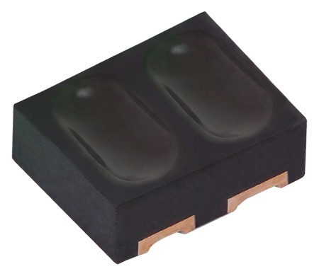
The angular position of the sprocket needs to be set accurately. A quadrature encoder will be needed to read a pattern in the sprocket wheel so a microcontroller gets position feedback for the closed loop control of the sprocket. A pair of tiny reflective reflective sensor will be used to create the quadrature signal.
![]()
![]()
Kinnow - Automatic Pick and Place Feeder
A low cost, stackable, automatic pick and place parts feeder that supports up to 24 mm tapes