 Hexabitz
-
13D-print a soldering fixture to hold modules together
We 3d-printed a shell model of half truncated icosahedron (soccer ball) shape to use as soldering fixture. Holes in the fixture are used to hold modules in place using M2 screws while being soldered.
-
2Solder the first half of the sphere
Solder the first half (10 modules). Start by doing the upper ring and attaching five modules to the fixture using M2 screws. Solder main joins (array ports) then remove the modules from the fixture and solder remaining joints from the other side (internal side). Put this back on fixture and attach the next five modules and solder them similarly.
Alternatively, you can also solder all ten modules from the outside, then remove the shell from the fixture and solder the internal joints.
![]()
-
3Solder the second half of the sphere and join the two halves together
Repeat step 2 by soldering the second half of the sphere. After that, put the two halves together and solder them from the outside and the inside. Try to get as many solder joint as possible. Particularly important are array joints (the ones in the middle of the module side) as you really need to solder all of them to get full connectivity. You can skip some power (corner) joints if they're hard to reach. This really requires some ninja soldering skills but it gets easier with training and better with patience.
We messed up dimensions a bit in the 3d-printed fixture and ended up with small displacements and alignment errors between modules. Solder surface tension helps you a bit in bridging these miss-alignments but you really need to be patient with such project and pay attention to dimensions because geometrical alignment is key. Once finished assembling the modules, you can add whatever connectors/wires you want (e.g., for power).
-
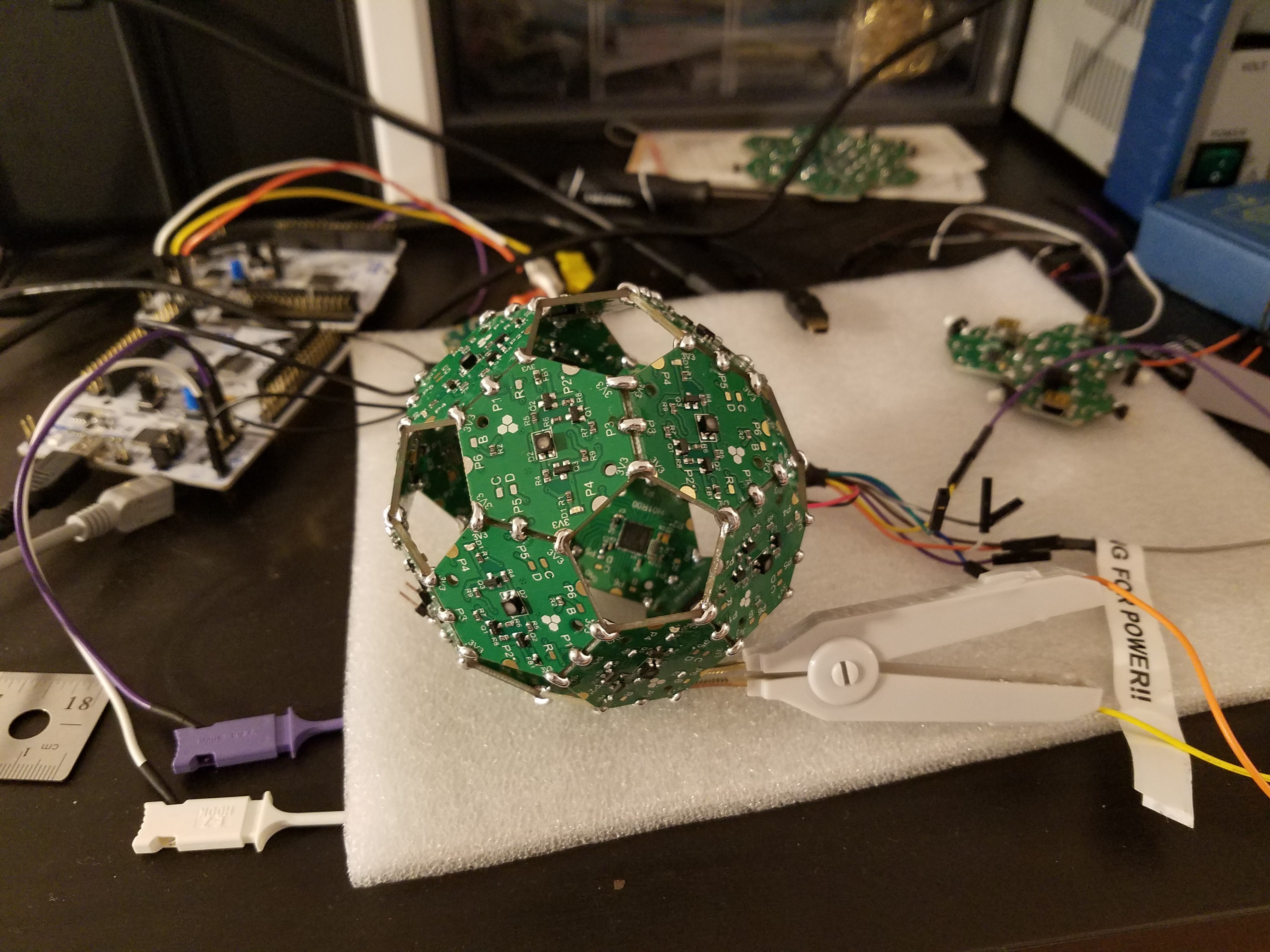
4Program the modules
This is a bit easier to do before assembly but using the modified Kelvin clamp really makes your job much easier!
![]()
-
5Power on!
Power on your beautiful creation! It's always better to power on such complex array first time from a current-limited power supply. It's possible you have a short somewhere and you don't want that to destroy a USB port! If all looks good, you can power the sphere completely from a single USB port. Its current draw is 300-400mA.
-
6Explore the array
Connect to any array port on any module via the CLI and run the explore command. After a minute or two (it's a slow process currently), all 20 modules will be discovered and a complex routing table will be constructed and displaed in the terminal along with all ports that must be swapped (top & bottom) to allow connectivity. The topology is saved to MCU Flash memory in each module so that next time you power up, no need to run array exploration again. Below is the terminal dump of the explore command.
==================================================== ==================================================== || Welcome to BitzOS CLI! || || (C) COPYRIGHT HEXABITZ 2016. || || || || Please check the project website at || || http://hexabitz.com/ || || || || Type help for a list of available commands. || ==================================================== ==================================================== Connected to module 0 (H01R0), port P6. >ping Hi from module 0 [Press ENTER to execute the previous command again] >explore The array is being explored. Please wait... Hi from module 2 Hi from module 3 Hi from module 4 Hi from module 5 Hi from module 6 Hi from module 7 Hi from module 8 Hi from module 9 Hi from module 10 Hi from module 11 Hi from module 12 Hi from module 13 Hi from module 14 Hi from module 15 Hi from module 16 Hi from module 17 Hi from module 18 Hi from module 19 Hi from module 20 The array exploration succeeded. I found 20 modules including myself. Here is th e discovered topology: (Module:Port) P1 P2 P3 P4 P5 P6 Module 1: H01R0 2:5 0 3:1 0 4:1 0 Module 2: H01R0 5:5 0 6:1 0 1:1 0 Module 3: H01R0 1:3 0 7:3 0 8:5 0 Module 4: H01R0 1:5 0 9:1 0 10:1 0 Module 5: H01R0 10:5 0 11:1 0 2:1 0 Module 6: H01R0 2:3 0 12:3 0 7:5 0 Module 7: H01R0 13:3 0 3:3 0 6:5 0 Module 8: H01R0 14:3 0 9:3 0 3:5 0 Module 9: H01R0 4:3 0 8:3 0 15:5 0 Module 10: H01R0 4:5 0 16:1 0 5:1 0 Module 11: H01R0 5:3 0 17:3 0 12:5 0 Module 12: H01R0 18:3 0 6:3 0 11:5 0 Module 13: H01R0 14:5 0 7:1 0 18:1 0 Module 14: H01R0 19:5 0 8:1 0 13:1 0 Module 15: H01R0 19:3 0 16:3 0 9:5 0 Module 16: H01R0 10:3 0 15:3 0 17:5 0 Module 17: H01R0 20:3 0 11:3 0 16:5 0 Module 18: H01R0 13:5 0 12:1 0 20:1 0 Module 19: H01R0 20:5 0 15:1 0 14:1 0 Module 20: H01R0 18:5 0 17:1 0 19:1 0 These ports are reversed: Module 2 : P5 Module 3 : P1 Module 4 : P1 Module 5 : P5 Module 6 : P1 Module 7 : P3 Module 7 : P5 Module 8 : P5 Module 9 : P1 Module 9 : P3 Module 10 : P1 Module 10 : P5 Module 11 : P1 Module 12 : P3 Module 12 : P5 Module 13 : P3 Module 14 : P3 Module 14 : P5 Module 15 : P5 Module 16 : P1 Module 16 : P3 Module 17 : P3 Module 17 : P5 Module 18 : P1 Module 18 : P3 Module 19 : P3 Module 19 : P5 Module 20 : P1 Module 20 : P3 Module 20 : P5 All other ports are normal [Press ENTER to execute the previous command again] > -
7LEDs dancing!
Send some broadcast LED commands and enjoy the show!
Sphere of Light
Build your very own disco ball with some ninja soldering skills a little help from the 3d printer

Discussions
Become a Hackaday.io Member
Create an account to leave a comment. Already have an account? Log In.