-
Linear PCB Motor vs Flexible PCB Actuator
08/09/2018 at 21:20 • 0 commentsIn this video, I have tested my Flexible PCB actuator and also compared it to my Linear PCB Motor which has the same dimensions but different layer count.
The measured data is shown bellow:
4-Layer Linear PCB Motor 2-Layer Flex PCB Actuator Resistance 32Ω 23Ω Maximum Temperature @ 5V 51°C 76°C Power 0.75W 0.9W The flex PCB has half the turns, so its resistance is lower. This means that more current can pass through it, so obviously it gets a little hotter. This means that this flexible pcb actuator can be used with lower voltages. The thin dielectric of this pcb also improves the coupling of the magnetic field.
-
Flexible PCB Actuator!
07/24/2018 at 17:48 • 0 commentsOk so lets be honest. I did not expected this thing to work. I was afraid that its resistance is going to be too small that it will over heat. But it actually didn't.
The pcb is dual layer and is 0.13mm thick. Although it only has 70 turns, the thin dielectric will improve the coupling. The flex PCB is made from a polyimide material which is highly resistant to heat, which makes the surface barely hot.
In the video I am driving with a 5V voltage supply and it is drawing around 600mA.
Comparison with the Linear PCB Motor prototype:
![]()
-
Flexible PCB!
07/09/2018 at 16:56 • 0 commentsI have just ordered a flexible pcb prototype for this project!
The pcb is dual layer and is 0.13mm thick. Although the number of turns have now reduced to 70, the thin dielectric will improve the coupling.
If this works it could open a whole other dimension of applications.
-
First Test with Slider!
06/27/2018 at 23:02 • 0 comments -
New Slider
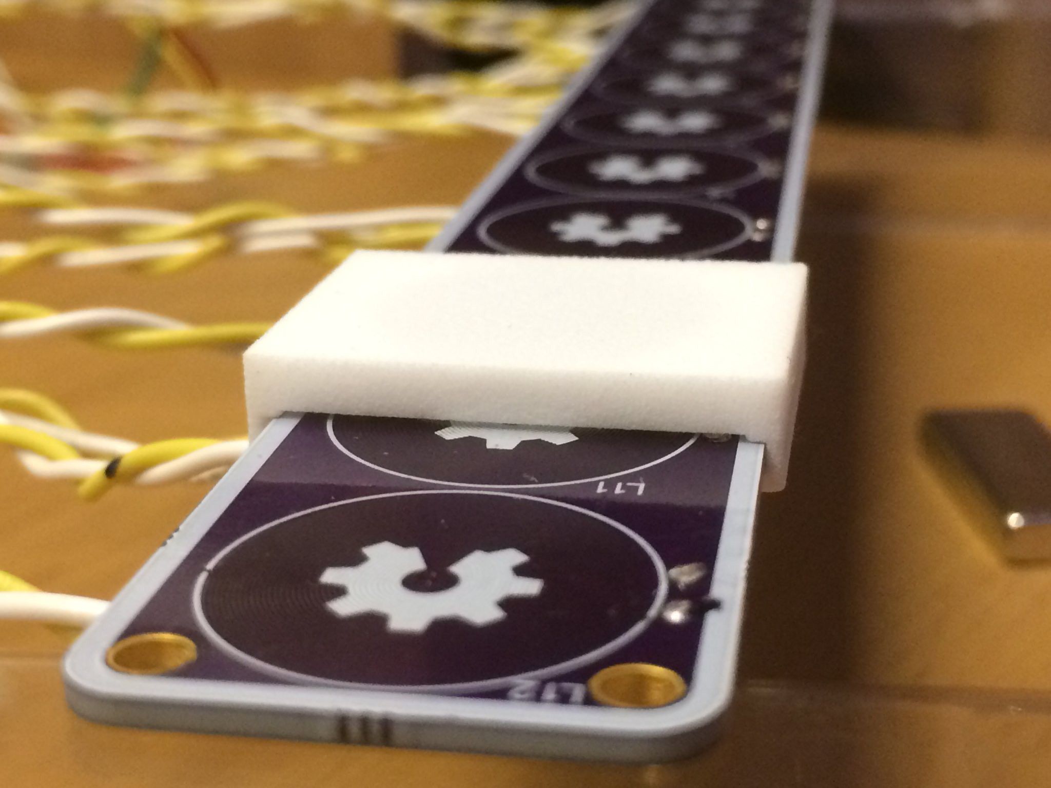
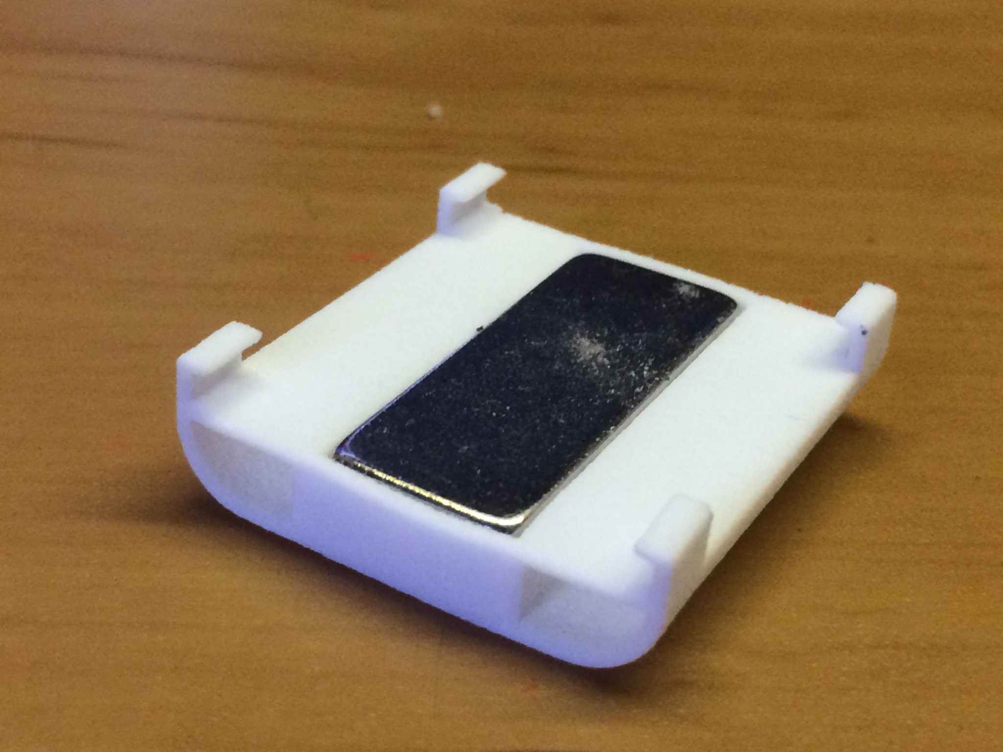
06/27/2018 at 21:58 • 0 commentsOk so I had to make some modifications to the slider design. The major issue was that I did not leave enough clearance for the pcb, so the slider was getting stuck in some regions.
![]()
The second prototype of the slider has less friction and houses a larger rectangular magnet.
![]()
-
New Test Board
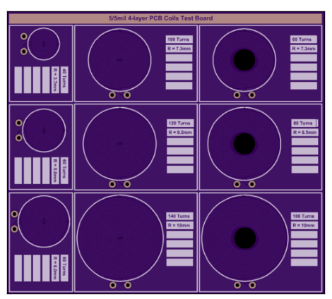
06/26/2018 at 20:22 • 0 commentsToday i have ordered some new test boards with a total of 9 pcb coils. These have different turns, to try and find the best size-to-strength ratio. Three of these coils also have a 5mm diameter hole in the middle to test them with an iron core.
-
Moving Ferrofluid!
06/16/2018 at 16:57 • 0 commentsThe magnetic field of the windings need to be a little stronger but the concept seems to be working. The idea is to have ferrofluid dancing around from a simple PCB. This is obviously just a concept but with more windings and perhaps with a core in the middle of these printed windings, it can be possible. (Also, I need to find a way not to stain the container with the ferrofluid .. its a little messy)
Since this does not actually have to do with the Linear PCB motor (although same pcb), I have set up a different project page for this:
-
Wiring & Driving Circuirty
06/16/2018 at 11:54 • 0 commentsThe first prototype of my Linear PCB motor has 12 coils. To simplify the electronics i have connected these in sets of 3, each having 4 coils in parallel for maximum current, and then in a delta configuration.
I am then using the STSPIN230 3-phase driver (available on the X-NUCLEO-IHM11M1 dev board) and controlling it with a DSPIC33EP128MC202-I/SP microcontroller.
-
PCB coil Testing
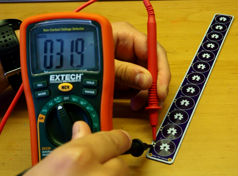
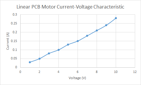
06/14/2018 at 22:35 • 0 commentsThe pcb coils have a total a 140 turns on 4-layers. These are creating a total resistance of 31.9ohms.
This is the current-voltage curve of an individual coil:
-
Jumping Magnets!
06/12/2018 at 00:18 • 0 commentsI accidentally made magnets jump when testing my Linear PCB Motor PCBs. This happened when I placed a small spherical neodymium magnet in the middle of the coil and alternating its magnetic field.
 Carl Bugeja