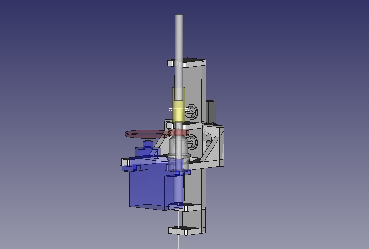
I transfered the basic idea into one single 3D-printable part and -surprise, surprise - it works!
This construction was my first time using FreeCAD for designing a non-trival part. Information about the new part/body model in version 0.17 isn't as easy to find and as comprehensive as I would wish for, but it worked. It starts to be a serious alternative to Solidworks now - at least for not too complex tasks.

The part is designed to be mounted onto a Drylin N17 linear rail. For the first tests I added a similar shaped adapter providing a Fischertechnik groove and used an old CD drive for the z axis.
Rotating the needle using a simple servo tester works quite well for servo rotations up to 90° (+/-45°). If I go further, the servo mount starts to bend up to the point where the gears start to slip. The mount needs more support at the back of the servo.
I expected small misalignments and added 1/2 teeth pitch (~0.8mm at M0.5) to the distance between the gears. This means accepting a noticeable backlash. Fortunately, this backlash turns out to be better than expected given the very generous extra distance between the gears. Not suitable for fine pitch applications, but definitely sufficient for aligning a 0603.
The part was designed to hold the luer lock and the needle by snapping them into partly open holes. This did not work at all. 3mm thick PLA is much stiffer than I expected. Experiments are needed to find the right geometry for snapping connections. Somebody must have researched that before, but I couldn't find anything on this topic yet. Any suggestions?
The needle is forced to be concentric by two supports.They are designed to be snapping connections, but this didn't work I had to cut them open wider than planned. In the end, the support is not as strong as I planned and there is a small amount of excentricity left. Probably ok for 0603, questionable for 0402.
So there is room for improvements. Main lessons for the next iteration so far:
- The servo mount needs a support at the back of the servo.
- researching the right geometry for snapping connections.
- The holder holes need to be a little bigger. +0.3mm of the desired size is the minimum for my printer, +0.5mm is probably better.
- The extra distance between the gears could be reduced. I will try 0.3 or 0.25 teeth pitch next time.
 Michael Mayer
Discussions
Become a Hackaday.io Member
Create an account to leave a comment. Already have an account? Log In.