Close
0%
0%

Smart Motor Driver for Robotics

This motor driver is able to control a motor using PID by I2C.
Taking precise control of a motor have never been so easy.

Similar projects worth following
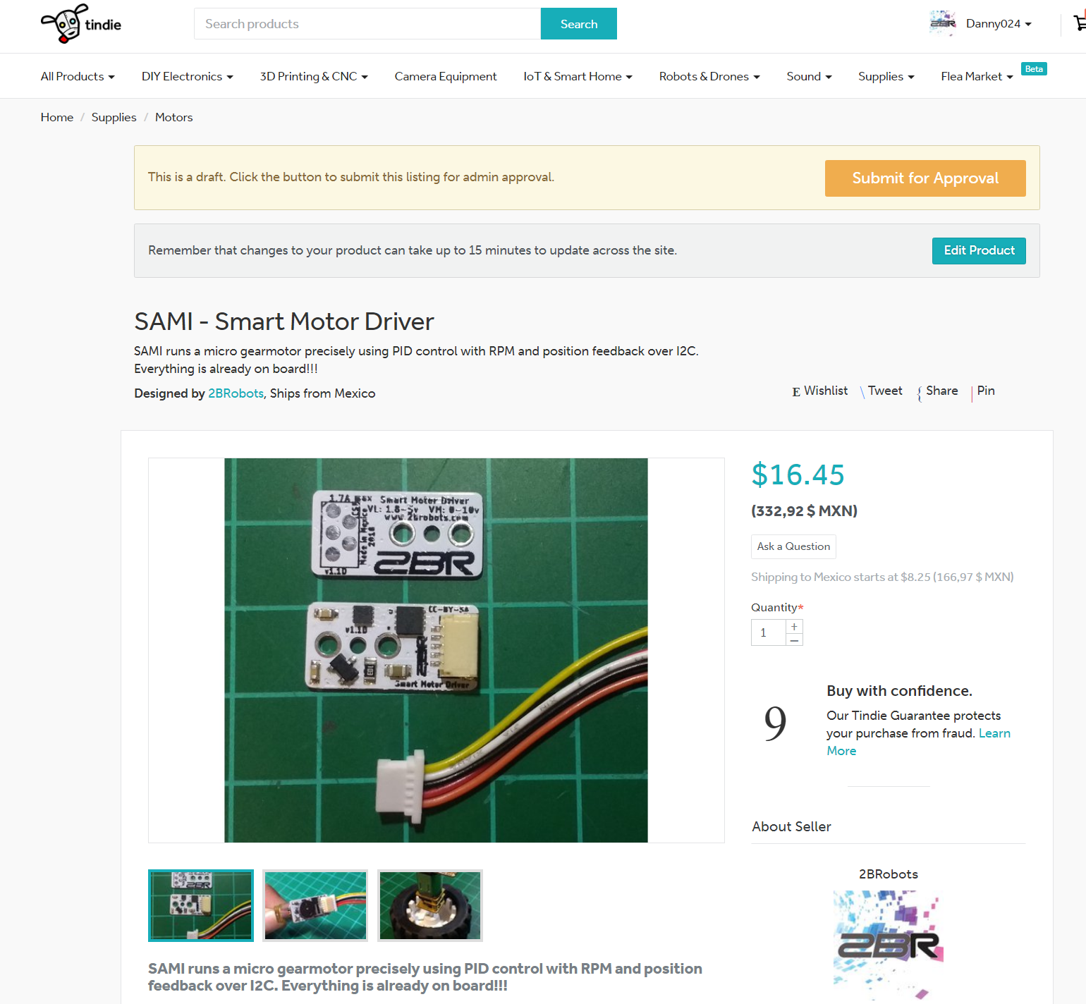
This is a Smart Motor Driver (aka SAMI) designed to run a micro gearmotor, the objective of this board is to implement a PID control over this motors with the corresponding RPM feedback. All required components are already on board, so it is capable of do the work by itself.
Just supply power and send orders by I2C!

The host controller communicates by I2C to give the commands to SAMI, this includes speed and direction of the motor. The module will automatically implement the PID control. So your host controller can just relax while this board takes care of the motor. Also you can read the status of the motor and set configs.

SAMI is capable of driving the motor for a desired distance or angle and then stop when is reached. This is ideal in robotics and simplifies a lot of hard work making precise movements. Multiple modules can be connected on a single bus, a lot of motors!

Making advance robots has never been so easy to anyone!!! Just solder the module to your motor.

This is the Smart Motor Driver (aka SAMI) designed to run a micro gearmotor, the objective of this board is to be able to implement a PID control easily over this motors with the corresponding RPM feedback using a hall effect sensor. So it has his own microcontroller and H bridge on board to be capable of do the work by itself.

The host microcontroller (or any system that can use I2C) communicates by I2C in order to give the commands to the smart driver module, this includes speed and direction of the motor. The module will automatically implement the PID to maintain the speed and apply more/less power dynamically in the motor to archive that.

I sell on Tindie

Also the control module is capable of driving the motor for a desired distance or angle and then stop when is reached. For doing that you must specify the diameter of your wheel and the gearbox relation.
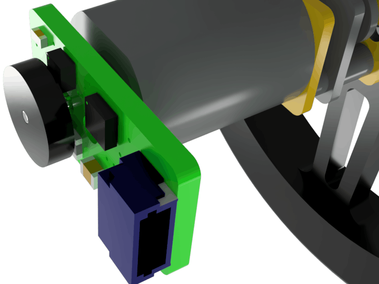
To sense the speed of the motor I used a magnetic encoder disk, it is polarized along the surface of the disk. So the hall effect sensor can detect the changes in the magnetic field of the disk and send the signal to the microcontroller. Then using the timer and interrupts we will calculate the RPM of the motor in second plane, so the microcontroller is free to run a PID control algorithm and handle the communication with the host. 

The main idea is to use it in robotics, so by using this modules to control the wheels of the robot it can be possible to make precise movements no matter the surface , the battery charge or even if the robot changes its weight!!!

Also it protects the gears from stripping due to a sudden acceleration or braking and will avoid the battery to trip the protection circuit caused by a current rush. So your precious motors will be safe!
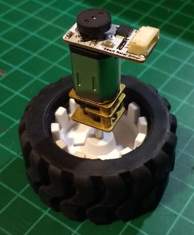
An Arduino library is available for easy use of SAMI, and you can plug a lot of motors fast and easy. 

Features:

  • Simple installation at the back of a micro DC motor.
  • Can control speed and direction of a motor.
  • Stops automatically when distance or angle is reached.
  • Multiple control modes, including simple PWM or PID with or without auto-stop. Plus a safe direction toggle option.
  • Works over I2C. The address can be changed by software.
  • Control a lot of motors, up to 128 modules can be in the same single I2C bus.
  • Internal pull-ups for I2C can be enabled/disabled by software.
  • Configurations can be saved on EEPROM.
  • Read the actual speed of the motor and check if a fail happens.
  • Fully configurable.
  • Easy to use high precision motor control.
  • Small package, just 2 cm x 1 cm.
  • Arduino library available.

Specs:

  • Motor voltage up to 11v.
  • Maximum motor continuous current as high as 1.7A and 1.8A peak.
  • Logic voltage from 3v to 5v. (1.8v range to being confirmed later after testing it)
  • Default I2C address is 0x24.
  • Protection against overcurrent and overtemperature.
  • To RESET default I2C address connect MCLR pad to GND at power up.
  • Standart 1mm 5 pin JST connector.

Benefits:

  • Independent motor control.
  • Smoother and precise movements.
  • Avoid breaking your motors.
  • Easy to use solution.
  • Built in motor speed feedback.
  • Highly responsive PID control to keep motor speed constant.
  • Avoid abrupt current peaks that can damage your power supply or battery.
  • Automatically stops at desired travel distance or angle if specified.
  • Powerful navigation solution for robots when combined with other sensors like an IMU.
  • Open source design. 

Installation:

For install SAMI to a motor you only need to solder it and place the encoder as shown in the next video:

IMPORTANT: your motor should have an extended shaft in order to allow...

Read more »

DESIGN_hard_soft-smart_motor_driver-1.0.0.zip

This are the pcb designs in EAGLE, schematic, gerber files for pcb fabrication and also all the firmware developed in MPLAB XC8. Also a 3D model is included and a file with its register map for controlling via I2C. Same files as in GitHub link.

x-zip-compressed - 12.45 MB - 10/01/2018 at 18:18

Download

Arduino_Library-Smart-Motor-Driver-1.0.1.zip

This is an Arduino Library designed to interface with SAMI easily. Examples included, same as in GitHub link.

x-zip-compressed - 12.57 kB - 10/01/2018 at 18:13

Download

I2C Memory Map.xlsx

In this excel file I show you all required register to interact with SAMI directly. Also control modes are explained on sheet 2 of this document. In the details section you can find this info as an image for easy viewing.

sheet - 24.95 kB - 09/09/2018 at 18:43

Download

BOM_Digikey.csv

Bill of Material from Digikey, this corresponds for the second revision that uses 12F1840 instead of 12F1822. For more details go to the materials section.

ms-excel - 1.05 kB - 06/26/2018 at 01:02

Download

smart_motor_controller.pdf

Schematic of the SAMI board in pdf format. For PCB files get it on EAGLE from the Github repository. Gerbers also included.

Adobe Portable Document Format - 15.70 kB - 06/01/2018 at 17:29

Preview

  • 1 × PIC 12F1840 Pic microcontroller
  • 1 × DRV8838 H-bridge motor driver
  • 1 × TLE4946-2K Hall effect sensor
  • 1 × SM05B-SRSS-TB(LF)(SN) JST 5 Position and 1mm pitch SMD connector
  • 1 × Magnetic Encoder Disc from Pololu Used to send the magnetic signal to the Hall effect sensor

View all 10 components

  • SAMI on action

    Danny FR08/08/2019 at 21:47 0 comments

    Hi, 

    The last time I wrote here was a long ago. Today I want to show you a robot made with SAMI. 

    In this demo you can see that the robot follows a straight path, then turns some times and after all returns exactly to the start point. Proving the precision of the controller:

    Specials thanks to my friend Emily Velasco for the cover picture n.n

  • Thank you for your support!!!

    Danny FR04/03/2019 at 17:13 0 comments

    It was  a long time wihout writing updates in this project. So today I want to tell you how this thing is going. First of all it was a succes, the boards are selling very well on tindie and a lot of people seems to like it. 

    Also in a few weeks a team of kids will be using them in a robot contest, and they have a great chance to win thanks to SAMI and how easy is to use them in a robot to program paths. Here is a small video that te kids send to me:

    Thank you very much for all! 

    I hope to have time soon and make some improvements thanks to the community feedback :)

  • Get your SAMI now!!!

    Danny FR01/16/2019 at 19:00 0 comments

    Hi, I just want to let you know that the first batch is already on sale on Tindie, get yours here:

    https://www.tindie.com/products/15726/

    Thank you

  • Available to purchase soon!

    Danny FR12/17/2018 at 02:08 0 comments

    I am happy to announce that SAMI will be available to purchase soon, I have some new motors with different gear ratios for final testing and at the same time I ordered required components for production and cool packaging materials are on the way to my house for this first batch. So stay tuned!!!

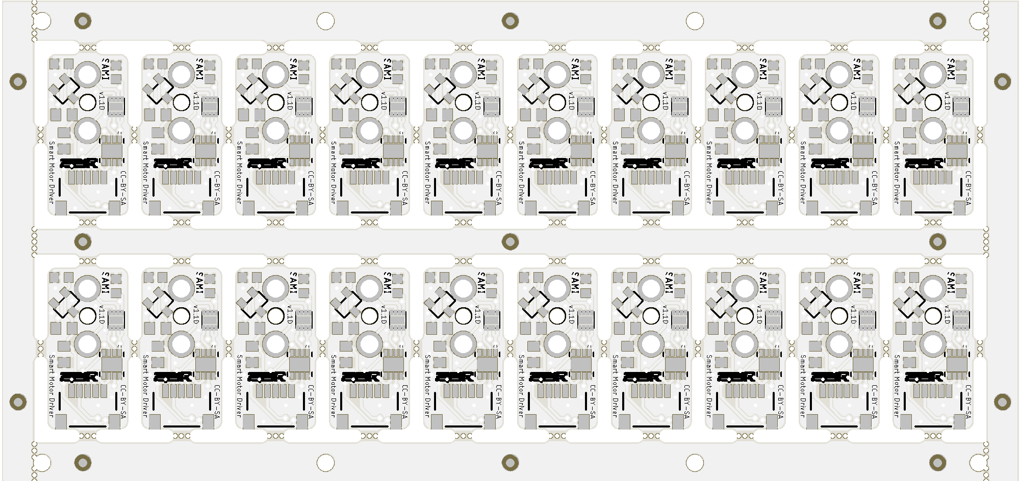
  • Panel ready for production

    Danny FR10/28/2018 at 01:15 0 comments

    I have panelized the boards for production and it looks like this:

    I hope that SAMI will be available for sale soon, thanks for all your support.

    Remember all files are available on the project repository, this is my very first panel for automatic assembly so any advice will be useful.

  • Limitations of SAMI and how it can be improved

    Danny FR10/21/2018 at 21:42 0 comments

    Today I want to talk about the development of the project, limitations and future improvements that could be done to achieve an even better and powerful Smart Motor Driver.

    As mentioned earlier in a previous log there are some limitations with the hardware and some things that only work in an ideal world. The first of all is about precision in Auto-Stop feature, a brushed DC motor can't be controlled to move exactly to a wanted position. Is just not possible, the encoder handles the measurement of this movement and working together with the PID control it does the best it can to move it to a desired position. The gearbox also plays a great paper in this, with a greater reduction relation it comes a bigger resolution and higher precision in the movements because the motor control doesn´t need to be that fine and the error gets reduced significantly. 

    However with a lower reduction relation in the gearbox the error in position grows because the motor movements are just not enough small to allow have that precision. Another important thing that can affect the precision is the inertia, so PID gains should be tuned properly to reduce influence of the inertia. Things that not exist in an ideal world, but in reality are present. 

    Also the encoder in SAMI uses only one channel, so it is less precise and can't detect direction of a movement induced by an external force in the system. All control algorithms on board suppose that only minimal external forces will be present, so take that in account when designing a solution with SAMI. The motor chosen in an application should be strong enough that an external force can't easily affect it. 

    I designed SAMI to be cost effective and useful in many robotics applications. And I think I got it right, for a normal robot movements is more than enough to the the job right in a super tiny solution. However I know there is applications that require a lot more of precision in the same tiny package, like a prosthetic hand or a robot arm. This is why I am designing a second SAMI with more resources that allow to have a much better performance, but also more expensive. 

    The main changes will be the addition of a full quadrature encoder (2 channels), motor current sense capability and a more powerful microcontroller, this will be distributed in a 2 PCB design to continue as a tiny solution. And this will be Pro edition of SAMI.

    With a better encoder SAMI precision will be 4 times better and reduce errors significantly. Also it will allow to use your DC motors as a servo and hold their position even with external forces actuating on them. Current sense can be used to detect limits at calibration in a linear actuator implementation. Opening the door to a hole new universe of applications, prosthetic hands can now be done better and cheaper than before. 

    And maybe one of the coolest feature will be that SAMI will be capable of record a movement and them repeat it. You will be able to program a robot arm by moving it with your hand while recording the movements with the encoder and them repeat it automatically sending it back to the motors.

    Soon SAMI will be available for sale and after that I will start working in the Pro edition. I have come with a beatiful open-source project with a lot of potential to change how robots and technology helps people live better. For me is a small contribution, but I think together as a community we have the power to do great things and help others using SAMI.

    Thanks to support the project.

  • New function!!! Auto-stop now works in angles too

    Danny FR10/12/2018 at 19:27 0 comments

    In this log I want to share a great new function. Somebody suggested me that it will be cool and useful that SAMI can be controlled also by sending angles, not just distance. So this is what I have done. The auto-stop function now accepts data in angles, not just as plain distance. So for example now you can ask SAMI to move 360°  directly to do a full wheel rotation instead of sending the wheel circumference as distance to obtain the same result.

    This was done as an easy upgrade, the code that does this is in the side of the library. Not in SAMI firmware. So is enough to download the new library to get the new function. You should know that SAMI receives/sends travel distance by encoder ticks and them the library converts this encoder ticks to distance using the wheel diameter as described in a previous log. 

    This allow us to just make a new equation for convert this encoder ticks to angles instead of distance. And it looks like this:

    Where steps are the encoder ticks, gear is the gearbox relation of the motor and angle is the desired angle to move. And then we add the new functions in the Arduino library to do conversions in angles for both directions (get and set): 

    int32_t SAMI_2BRobots::getAngle(void) {
       	int32_t value = (int32_t)read32(SAMI_REG_DISTANCE_0);
         	value = (int32_t) ((double)(360*(double)value)/(3*(double)getGear()));
    	return value;
    }
    
    void SAMI_2BRobots::setAngle(int32_t value) {
         value = (int32_t) (((double)(3*(double)getGear())/360)*(double)value);
        }

     As you can see is the same as done in distance conversion, just using the new equation.

    Here you can see a small demo, firts its moves 360°, then -180°, after that 90° and finally -270° to return to the same start position.

    The new library update is already available with the example included.

    Thanks for reading :)

  • PID speed and distance reactions

    Danny FR10/07/2018 at 18:25 0 comments

    Hi

    Today I wanted to show you a small video about the PID control typical reactions.

    In the next video you can see a robot with 4 wheels, when I grab one to stop it at the time of release it an overshoot is caused. Next the wheel stabilises its speed but the distance gets a little bit off, so the motor now moves forward until it reach the desired position. 

    Also you can see that the other wheels don't move until the one I grab finish its movement, them every wheel continues with the sequence.

    This is ideal in a robot because it allows to sequence complex movements routines and automatically waits every motor is done before continue. This is done thanks to my library for Arduino that checks the "isRunning" flag to coordinate the sequences. This code is in the examples.

    However this also introduces a new problem into the equation. What happens if motors gets slightly unsynchronized? Well the robot will not navigate so precisely or even do weird things in extreme scenarios. To correct this you should do a check in your master controller and keep things synchronized by getting is something unexpected happens. Also is a good idea to use a IMU to completely take off the error, other kinds of sensors can help too. 

    What I want to say, is that SAMI would not make a miracle by itself. But together with clever programming and joining forces with other sensors can be an unbeatable navigation system. 

    Thanks for reading :)

  • PID gains auto-tunning

    Danny FR10/04/2018 at 03:38 0 comments

    Today I am going to talk about something that is included on the Arduino library for SAMI. It is a little program that allow to obtain automatically the gains required for the PID control algorithm for both speed and distance controllers. 

    It is based on the Ziegler-Nichols method, it is not too accurate but will do the job for most applications. Fine human tuning may be necessary in some cases. After all the fun is in experiment and watch the different reactions of the system with different values. 

    This time I didn't do the job alone, the calibration code uses jack01 autotuner library and is already modified to work straight forward with SAMI for easy setup. However you must download his library separately to respect his amazing work with this Arduino Library.

    Let's say no more and watch it in action:

    Remember, this example and other useful ones about how to use SAMI are available in my Arduino Library. You can install it directly with the Arduino IDE Library manager, just serch "SAMI" and install the one that says my name on it ;)

  • How auto-stop algorithm knows it finish and stops

    Danny FR09/30/2018 at 23:00 0 comments

    Today I wanted to document how the auto-stop code works, this is now one of my favorite features of SAMI because it allows to do any other thing in the main controller while SAMI takes care of speed and traveled distance and then stop automatically using precision PID control. With some extra sensors like an IMU and a little bit of coordination in the main control to all SAMI's it can really do a big difference when controlling robot movements. 

    So here is the code that powers this feature:

    if (I2C_buffer.data.DISTANCE != 0 && loadDistance == 0) {
                            loadDistance = 1;
                            auxDistance = I2C_buffer.data.DISTANCE;
                            I2C_buffer.data.DISTANCE = 0;
                            stable = 0;
                        } else {
                            calculate_pidM(calculate_pidA(auxDistance));
                            if (auxDistance >= I2C_buffer.data.DISTANCE - ATS_tolerance && auxDistance <= I2C_buffer.data.DISTANCE + ATS_tolerance) {
                                stable++;
                                if (stable > stable_time) //travel distance stable at desired value for at least some time
                                {
                                    loadDistance = 0;
                                    M_control(0);
                                    I2C_buffer.data.START_STOP = 0;
                                }
                            } else {
                                stable = 0;
                            }
                        }

    As you can see when you first set the desired distance it loads into a temporal variable and then clears the register and sets a flag to know that it has been set-up. After that the algorithm starts running, we use the previously discussed PID control equations, but this time using the desired distance as the setpoint, the encoder traveled distance as an input and the output is going to be the RPM's to run the motor. They can't be higher that the RPM's limit set by the user. 

    Now this is the important part, we have a flag to stop the motor when we reach the desired position, otherwise it will run forever making the motor overheat and also shaky due to the algorithm trying to hold the position. So to prevent that I have make a clever condition that basically waits some time before disabling the controller only if it is stable in the desired position. Obviously the desire position has a range up and down, because it will be almost impossible for a common DC motor to make too precise movements.

    After the algorithm stops the motor when done, also clears the running condition flag in the driver. So now the host controller will now that SAMI has done and is ready to receive a new order. Pretty useful for sequencing moves in a robot without the "delay thing" hassle. 

View all 36 project logs

  • 1
    Gather all the parts

    The first thing you wanna do to build your own is to get all the parts. Please go to github and download the eagle files of the board. You can upload directly the design to Oshpark, if you want to use another manufacture service you will need the gerber files. Board must be 0.8mm thick!!!

    Now purchase all the parts, you can get it on Digikey, but be careful when selecting the size and the case style. Make sure everything is correct and in the right size, capacitors must be rated for at least 16v. The BOM is attached here, just download it for easy ordering.

    Optionally order the stencil, it will save you a lot of time and frustration when soldering. You can get one on Oshstencils. 

  • 2
    Solder all the parts

    Apply solder paste to the board using the stencil. Now put the SMD parts in place, make sure to put it in the right way. Check where and how the parts go using the EAGLE board files. Then you can solder it using hot air or a reflow oven. Just be careful, it's pretty easy to make a mess with this tiny components.

    Finally solder the motor in place making sure is centered to the shaft hole, then put the encoder disk in place.

  • 3
    Burn the firmware

    Now using a PIC microcontroller programmer (like the Pickit 3) burn the supplied firmware into the board. I used pogo pins to make the connection between the board and the programmer.  Check ICSP pin order on the EAGLE files or in the details section.

    Remember this project is under development, so I will be changing and updating the firmware until it supports all the functions wanted. Right now the final version is complete, but there might be updates in the future.

View all 4 instructions

Enjoy this project?

Share

Discussions

yongbinjin wrote 02/23/2019 at 05:42 point

Sir, I wanna design a current close loop driver for this kind of small DC, Do you have any suggestion?

  Are you sure? yes | no

Danny FR wrote 02/26/2019 at 02:16 point

Hi, yes! The most important one is to choose an enough powerful microcontroller, do the sensor readings using hardware interrupts and be careful organizing your code and how often the data refreshes.

pd: *miss

  Are you sure? yes | no

Deltaprintr wrote 01/25/2019 at 03:19 point

What's the angle that this motor can be controlled at with this encoder? For example, we plan to use it for a pick and place machine to advance feeder tapes. N20 motors tend to be generally fast (so we need to slow it down) and if lets say we use 0402 or smaller, we need to advance the tape very little and precisely. Can this encoder do that? Or are there limitations? If so, what are they?

  Are you sure? yes | no

Danny FR wrote 01/26/2019 at 02:55 point

Hi, SAMI can detect 3 pulses per motor turn (in the motor shaft). The precision achieved varies with the gearbox on the motor. For example, if you have a 1:100 gearbox that would be 300 pulses per turn on the gearbox output shaft.  You can read more about this here: https://hackaday.io/project/158429-smart-motor-driver-for-robotics/log/154988-limitations-of-sami-and-how-it-can-be-improved

For your feeder I would recommend using 1:1000 gearbox (is the bigger gearbox I have seen on a N20 motor), that would give you a great angle resolution. With this gearbox the motor would move only at 35 RPM max. Remember that the feeder roller diameter also plays a card in the game. 

I believe that is completely possible to do an SMD feeder with my smart motor driver, the proper gearbox and a good feeder mechanism, however I can't guarantee the repeatability on the final system. The only way to know is trying it out.  

  Are you sure? yes | no

Deltaprintr wrote 01/26/2019 at 03:59 point

Wow thanks so much for the detailed explanation! We will definitely explore using this encoder for our application! 300 pulses sounds amazingly precise for one rotation. Thanks! - Shai

  Are you sure? yes | no

Danny FR wrote 01/26/2019 at 23:46 point

No problem, glad to help! :)

  Are you sure? yes | no

Danny FR wrote 12/30/2018 at 02:25 point

Hey, this project is now available for purchase. If you use the coupon GETSAMI you can get 10% off until january 10. Check it here: https://www.tindie.com/products/15726/

  Are you sure? yes | no

Tomas Feltl wrote 11/08/2018 at 20:05 point

Great project!  We are looking for something like this for our 3D printed robot construction kit... https://hackaday.io/project/158815-m-bitbeam-construction-set

  Are you sure? yes | no

Danny FR wrote 11/12/2018 at 18:44 point

Thanks, your kit looks cool!!! Of course you can use my motor controller for your project. And if I can help in any way just let me know.

  Are you sure? yes | no

peter jansen wrote 08/04/2018 at 06:59 point

This is a great project!  I was interested in doing something similar with these micro gear motors a year or two ago -- it turns out they're much less expensive if you get them directly from China (e.g. https://www.banggood.com/search/micro-gear-motor.html ).

  Are you sure? yes | no

Danny FR wrote 08/04/2018 at 17:54 point

Thanks, if I can help in some way just let me know! 

Great tip :)

  Are you sure? yes | no

peter jansen wrote 08/05/2018 at 04:47 point

One of the things I was trying to work on is how to create essentially a linear servo or square-shaped piston using these motors, with the caveat that it had to be as small a square with as long a throw as possible (at least 4-6 inches), to try and make one of those pin-bed displays like from one of the x-men movies, where they essentially combine thousands of linear actuators to make a variable height map.  But to make it happen, you'd have to make them /really/ inexpensively, likely sub-$5 each, and ideally REALLY inexpensively, in the sub-$2 range, so that you can build literally thousands of them.   I have almost completely shelved the idea, but it's an interesting use case to think about when trying to make inexpensive actuators such as this. 

  Are you sure? yes | no

Danny FR wrote 08/05/2018 at 22:28 point

Sure, they definitely can be used to create a linear servo with a square shaped piston to make a pin-bed display. The simplest , cheaper and compact mechanism I can imagine at the moment is a thread rod and a nut attached to the base of piston with motor at the end and a limit switch for first calibration at start up. Them motors can use this driver to track and set the desired position of the piston. 

However it won't be so cheap, maybe something around $20 per piston. I would be interesting to make a quotation for some thousands units and see how much the cost lowers. But surely a prototype and a lot of experimentation will be necessary before thinking in mass production.

  Are you sure? yes | no

Similar Projects

Does this project spark your interest?

Become a member to follow this project and never miss any updates