0%
0%
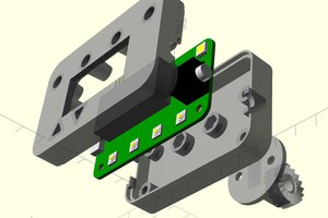
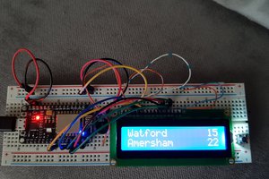
Morse Code Decoder
A device for decoding very fast 'contest speed' Morse Code.
 Steve Smith
Become a Hackaday.io member
Already have an account? Log in.
Just one more thing
To make the experience fit your profile, pick a username and tell us what interests you.
Pick an awesome username
hackaday.io/
Your profile's URL: hackaday.io/username. Max 25 alphanumeric characters.
Pick a few interests
Projects that share your interests
People that share your interests


 SUF
SUF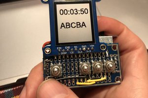
 terryspitz
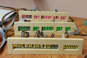
 Atheros
man. you got a source code for the 328? ...and you load the fw through the arduino board then swapping the 328 on the pcb I guess..