Close
0%
0%

ELM

Electromagnetic Lifting Module

Similar projects worth following
Since Amazon Prime Air service was announced automated packet delivery has become more and more popular. Concept promises faster "last mile" deliveries at a fraction of the cost.

Airbound and earthbound autonomous systems are getting more and more popular with makers and enthusiasts. By building more modules aimed at specific task that can be easily incorporated into various robotics systems, concepts like automated packet delivery are closer to becoming a reality.

When adding lifting capability to you robotics systems you are limited in your selection of grippers. Popular choices are mechanical or suction grippers. ELM is designed to give you more options for gripping your objects and to widen the specter of tools you have at your disposal.

ELM incorporates electromagnet to do the task of lifting or dragging objects. There are benefits and disadvantages to this approach:

PROS (compared to mechanical grippers): 

  • Cheaper, easier maintenance and reliable (no mechanical joints)
  • More reliable grabbing and dropping of object
  • Stronger grip than mechanical grippers
  • Doesn't use mechanical force to press on the object
  • Smaller and lighter the larger in volume object gets
  • Easier to interface with system from software side

CONS (compared to mechanical grippers)

  • Objects need to be metal or need to have metal gripping area
  • Consumes electricity during entire operation
  • Force holding the object is concentrated in smaller surface area 

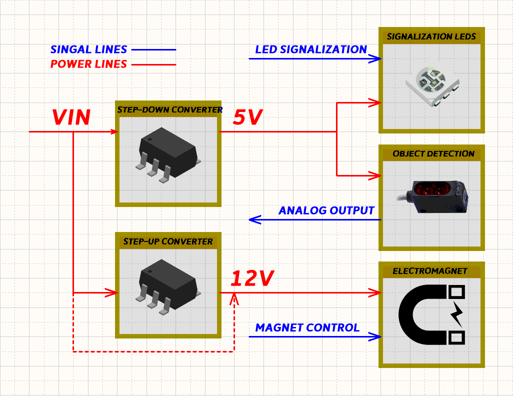
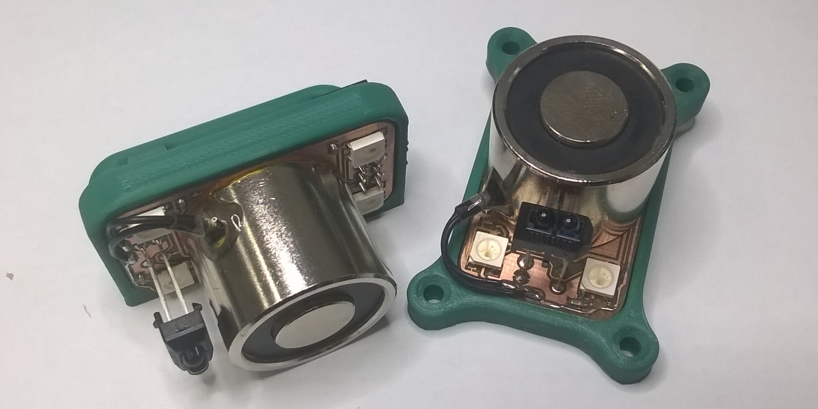
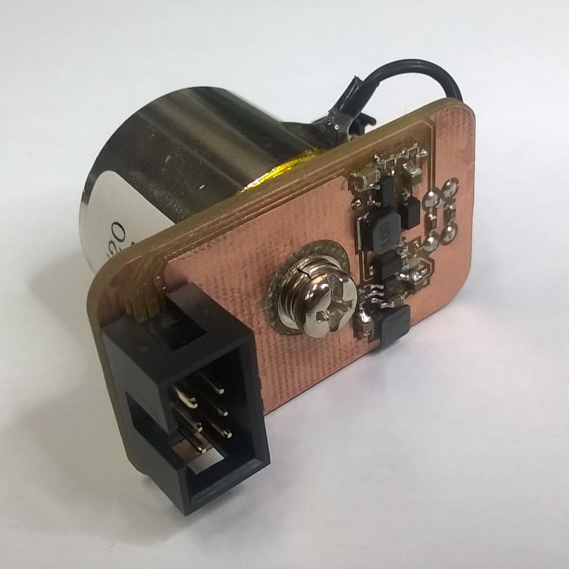
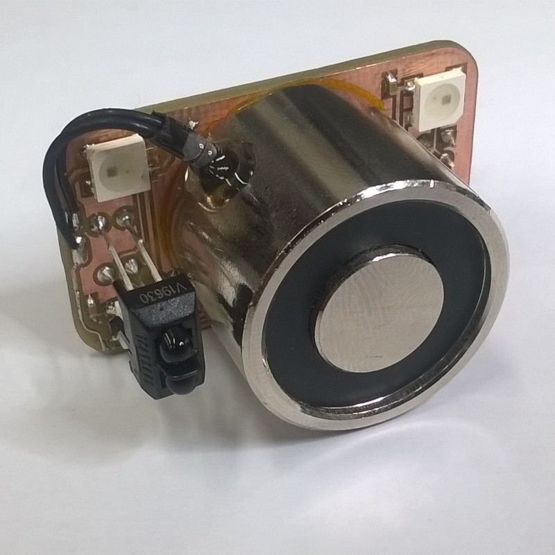
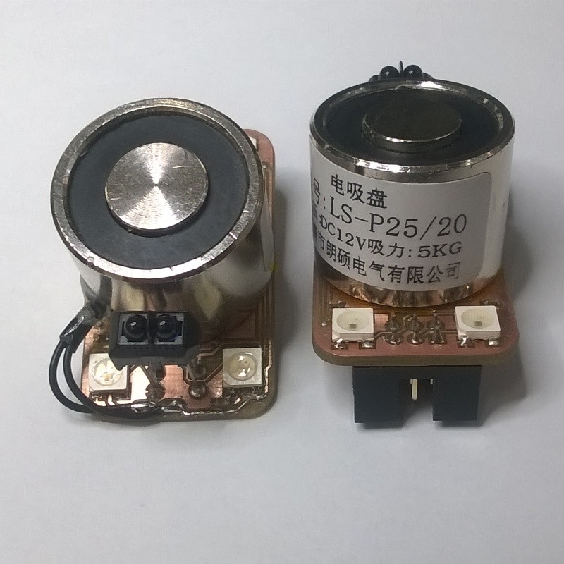
Electromagnet mounted on ELM needs 12 volts DC to operate. If your system voltage is lower than 12 volts, onboard boost converter can be used to power the electromagnet. In systems where voltage is around 10 to 15 volts boost converter can be omitted with jumper. ELM also includes reflective optical sensor to detect if object is present and LEDs for optical signalization. LEDs and sensor can be powered by on-board step down converter or external voltage. Module is interfaced with system via 6 pin IDC connector. 

Project is published under MIT License. For more information visit this link.

ELM - HorizontalHolder.STL

Standard Tesselated Geometry - 2.98 MB - 06/03/2018 at 21:00

Download

ELM - VerticalHolder.STL

Standard Tesselated Geometry - 2.67 MB - 06/03/2018 at 21:00

Download

ELM - Schematics.PDF

Adobe Portable Document Format - 387.88 kB - 06/03/2018 at 20:55

Preview

ELM - Assembly drawing.PDF

Adobe Portable Document Format - 176.09 kB - 06/03/2018 at 20:55

Preview

ELM - Gerbers.zip

x-zip-compressed - 22.10 kB - 06/03/2018 at 20:54

Download

  • ELM Testing

    Mile06/03/2018 at 20:49 0 comments

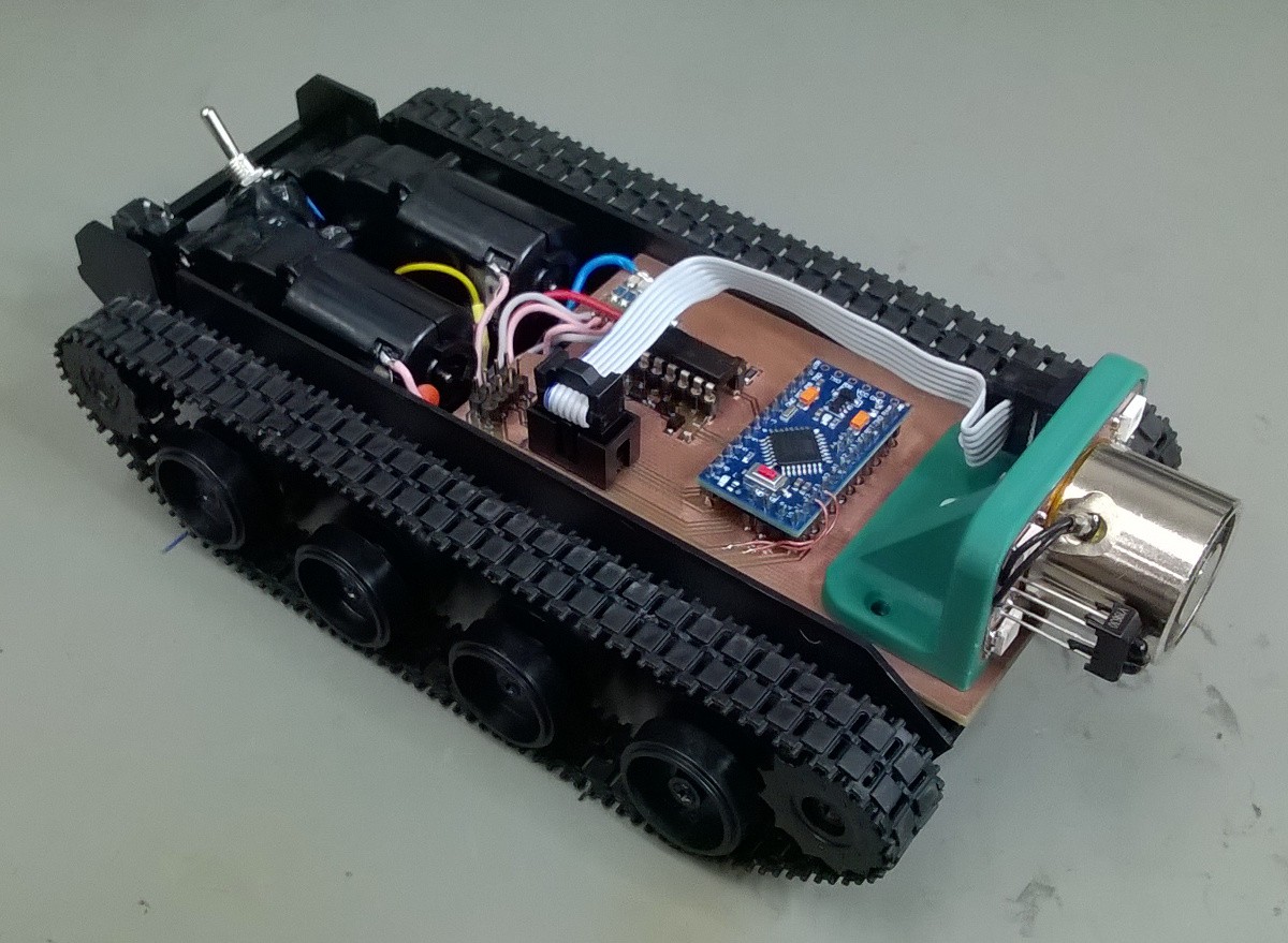
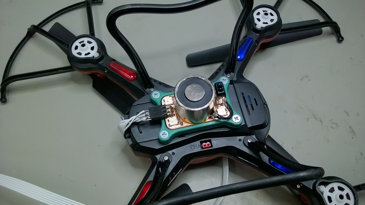
    As stated before ELM can be used on airbound and earthbound systems. Here are some pictures for both cases. Second picture is just symbolic since quadcopter I have is just a toy and barely can lift any additional weight besides ELM.

    Here is also video showing some tests when ELM is mounted on tracked chassis. In the video when the object is picked up leds don't change color because proximity sensor wasn't calibrated.

    Testing of the module hes determined that further development of the module needs to follow these points:

    • Adding a way to adjust electromagnet voltage on the go to reduce power consumption
    • Optical sensor has trouble sensing non reflective surfaces. Mechanical microswitches?
    • Building versions with smaller, bigger or multiple electromagnets.

  • Assembling modules

    Mile06/02/2018 at 20:25 0 comments

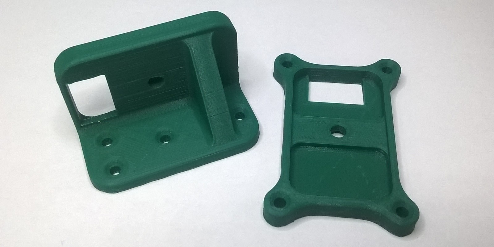
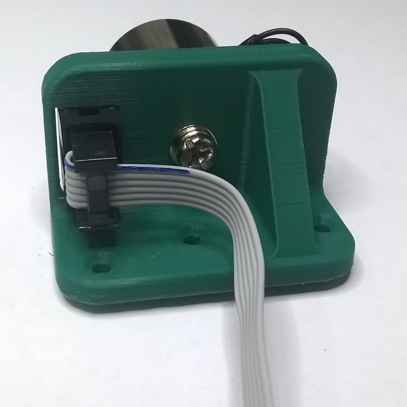
    Depending on the system requirements module will be mounted horizontally or vertically. This will be achieved with custom designed holders that can be printed.

    Holders were printed with PLA/PHA filament and 0,1 mm layer height (thicker layers can be used). Print time with 0.1 mm layers is about two hours for vertical and one hour for horizontal holder. No supports are needed.

    Short video that shows testing of ELM. Module is tested by lifting object weighing 1 kg. Test showed that for that task module consumes 380 mW of power. Only 220 mW of power is needed to lift the load. Remaining 160 mW is used by LEDs and proximity sensor. If power consumption is an issue LEDs and sensor can be omitted.

  • Assembling PCBs

    Mile06/02/2018 at 18:54 0 comments

    Pictures below show assembled PCBs. All components can be soldered using only soldering iron with fine tip. Since my PCBs were milled I had to manually connect vias. Best thing to use is solid core hookup wire. Also there were some traces damaged during milling so they needed to be repaired. All in all it took me 30 minutes to assemble the complete module.

    To ease assembly process I like to mark components I already placed.

  • Designing and making PCBs

    Mile06/02/2018 at 18:45 0 comments

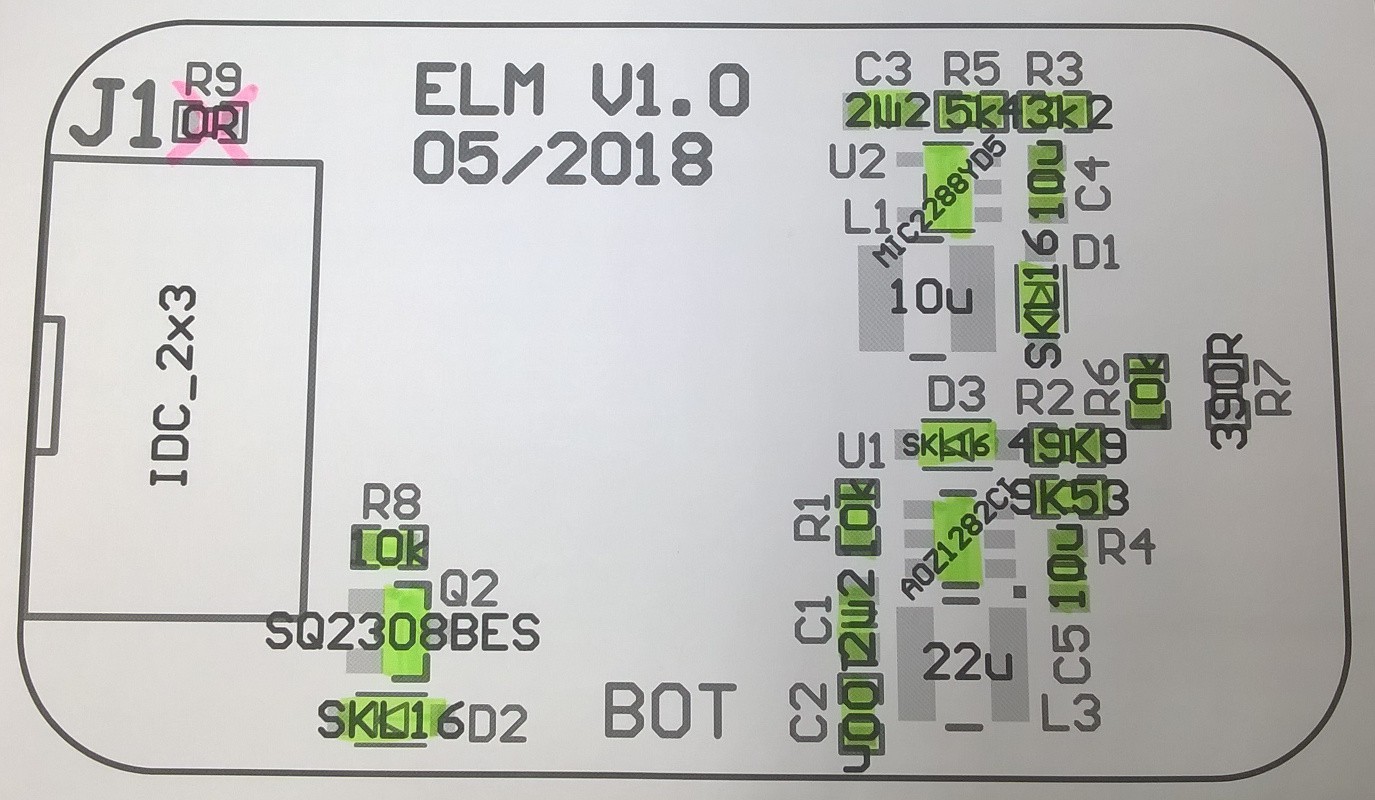
    PCBs for this project were designed with ease of reproducing in mind. Main goal was to achieve smallest size as possible to reduce the cost of fabrication while still being relatively easy to assemble. Components used are in SOT, SOD, 5050 and 0603 packages. Hardest components to solder are SOT packages because. Switching converter in bigger packages just aren't available. Tight layout of components is necessary to ensure optimal operation of switching converters. 3D preview of the module.

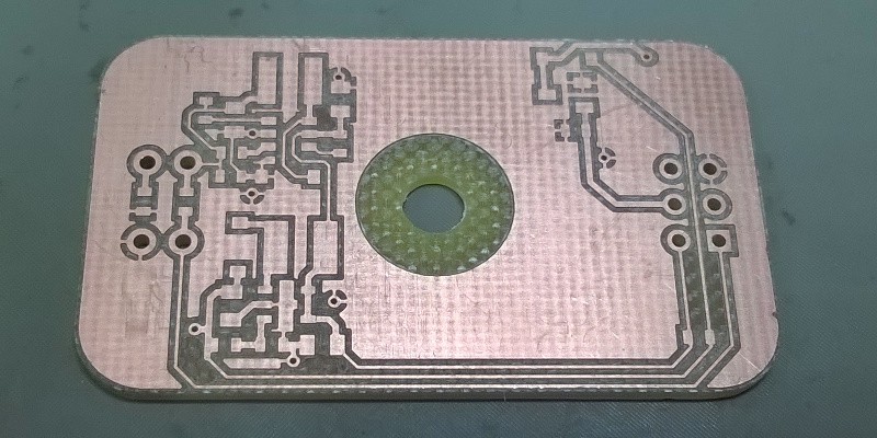
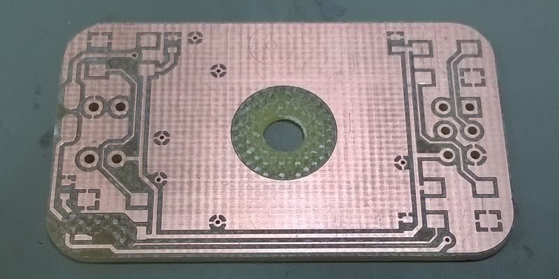
    To make assembly process easier assembly drawing is included. Bottom pictures show milled PCB (bottom and top side). Some traces are damaged so I will have to repair them with jumper wire.

View all 4 project logs

Enjoy this project?

Share

Discussions

Josh Cole wrote 07/27/2018 at 04:55 point

Heck yes! This is really awesome.

  Are you sure? yes | no

Similar Projects

Does this project spark your interest?

Become a member to follow this project and never miss any updates