Mile
Mile-
ELM Testing
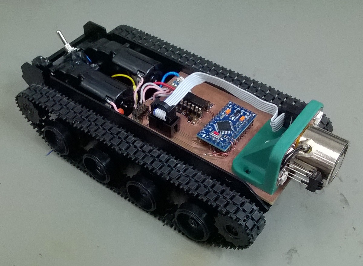
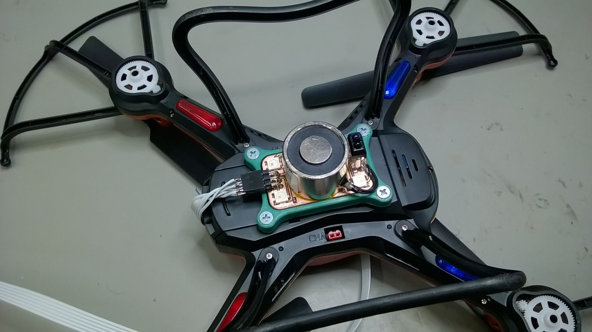
06/03/2018 at 20:49 • 0 commentsAs stated before ELM can be used on airbound and earthbound systems. Here are some pictures for both cases. Second picture is just symbolic since quadcopter I have is just a toy and barely can lift any additional weight besides ELM.
![]()
![]()
Here is also video showing some tests when ELM is mounted on tracked chassis. In the video when the object is picked up leds don't change color because proximity sensor wasn't calibrated.
Testing of the module hes determined that further development of the module needs to follow these points:
- Adding a way to adjust electromagnet voltage on the go to reduce power consumption
- Optical sensor has trouble sensing non reflective surfaces. Mechanical microswitches?
- Building versions with smaller, bigger or multiple electromagnets.
-
Assembling modules
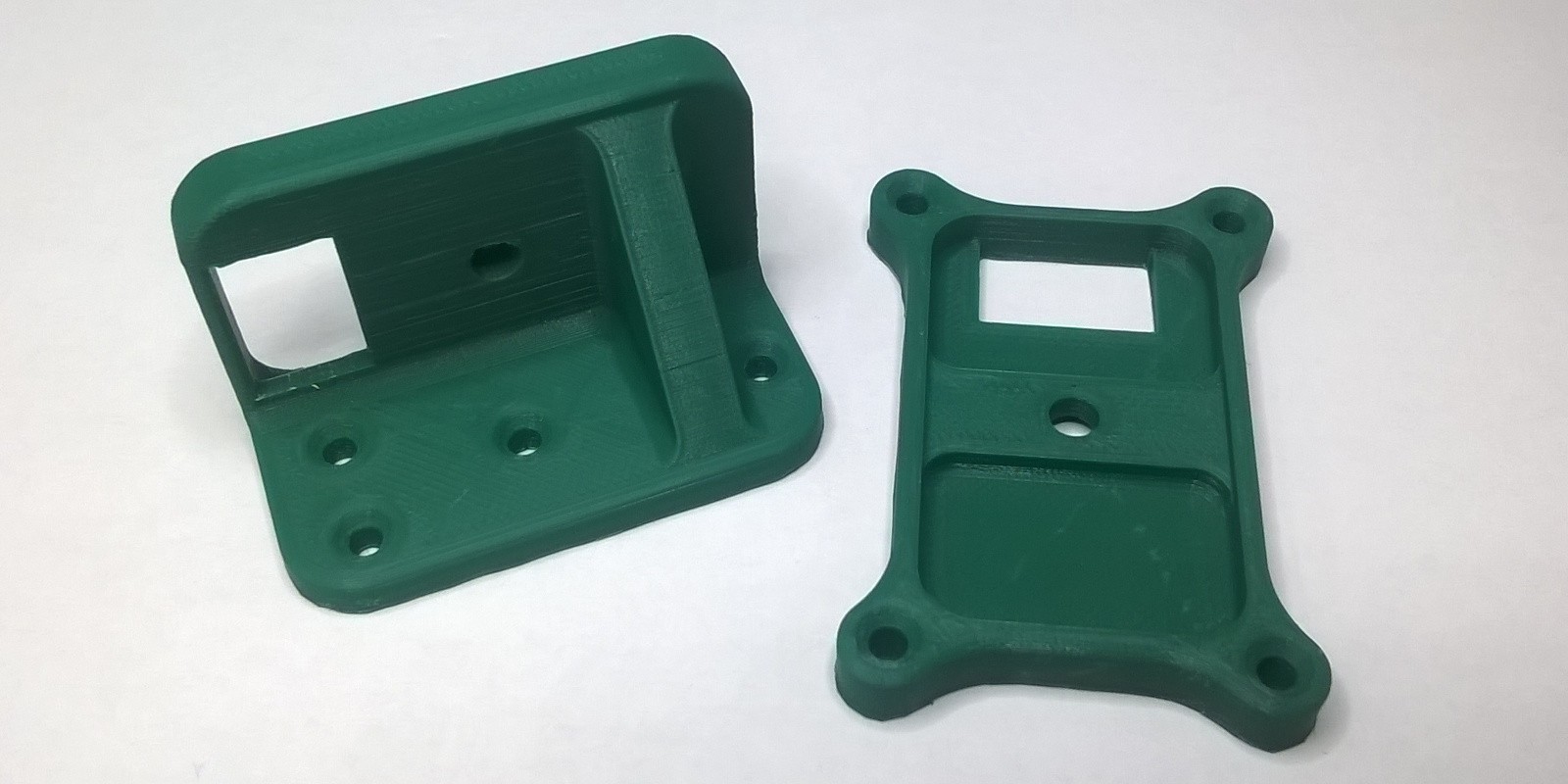
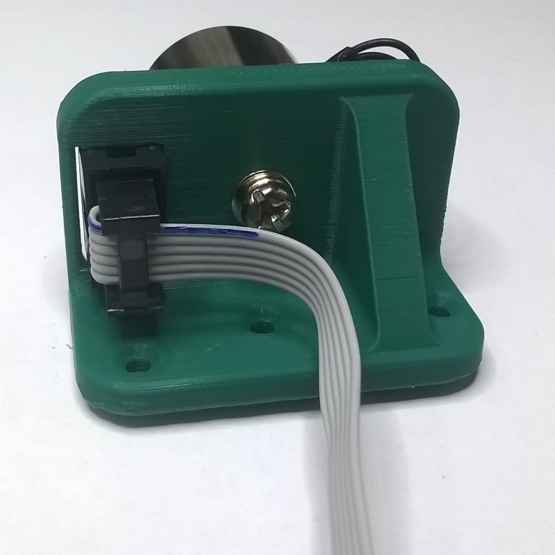
06/02/2018 at 20:25 • 0 commentsDepending on the system requirements module will be mounted horizontally or vertically. This will be achieved with custom designed holders that can be printed.
![]()
Holders were printed with PLA/PHA filament and 0,1 mm layer height (thicker layers can be used). Print time with 0.1 mm layers is about two hours for vertical and one hour for horizontal holder. No supports are needed.
![]()
![]()
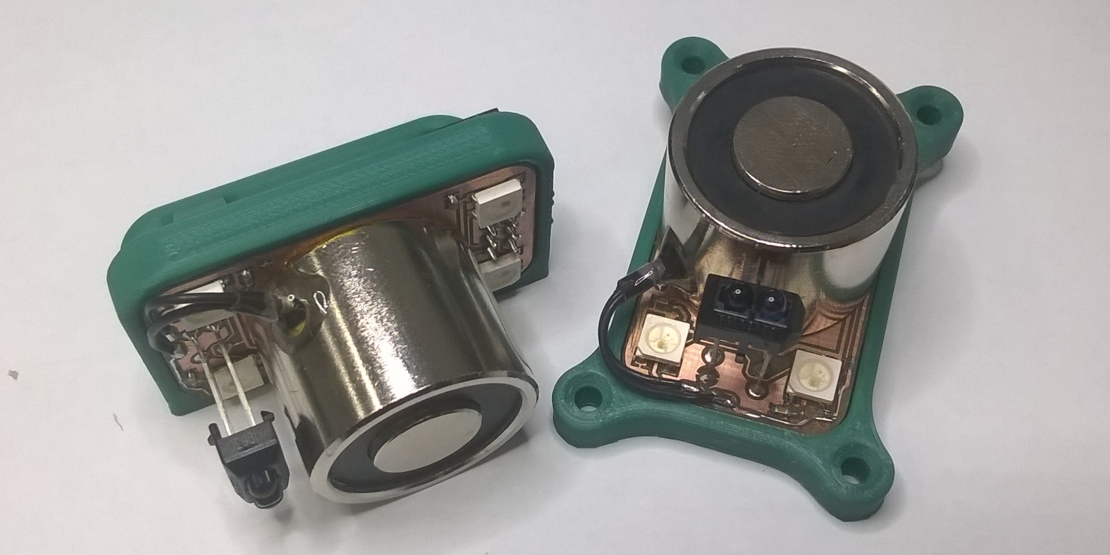
Short video that shows testing of ELM. Module is tested by lifting object weighing 1 kg. Test showed that for that task module consumes 380 mW of power. Only 220 mW of power is needed to lift the load. Remaining 160 mW is used by LEDs and proximity sensor. If power consumption is an issue LEDs and sensor can be omitted.
-
Assembling PCBs
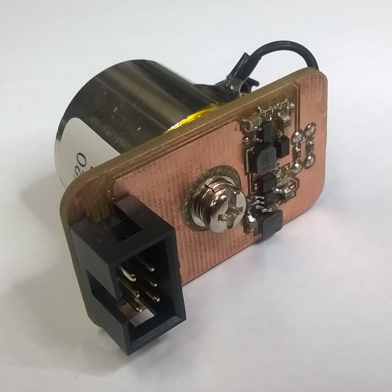
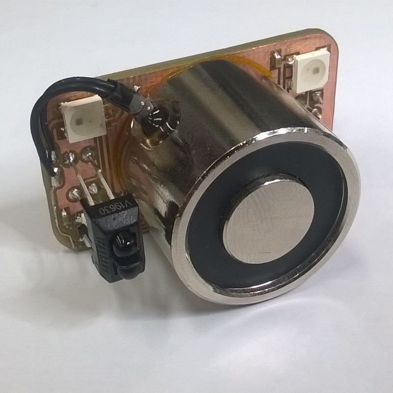
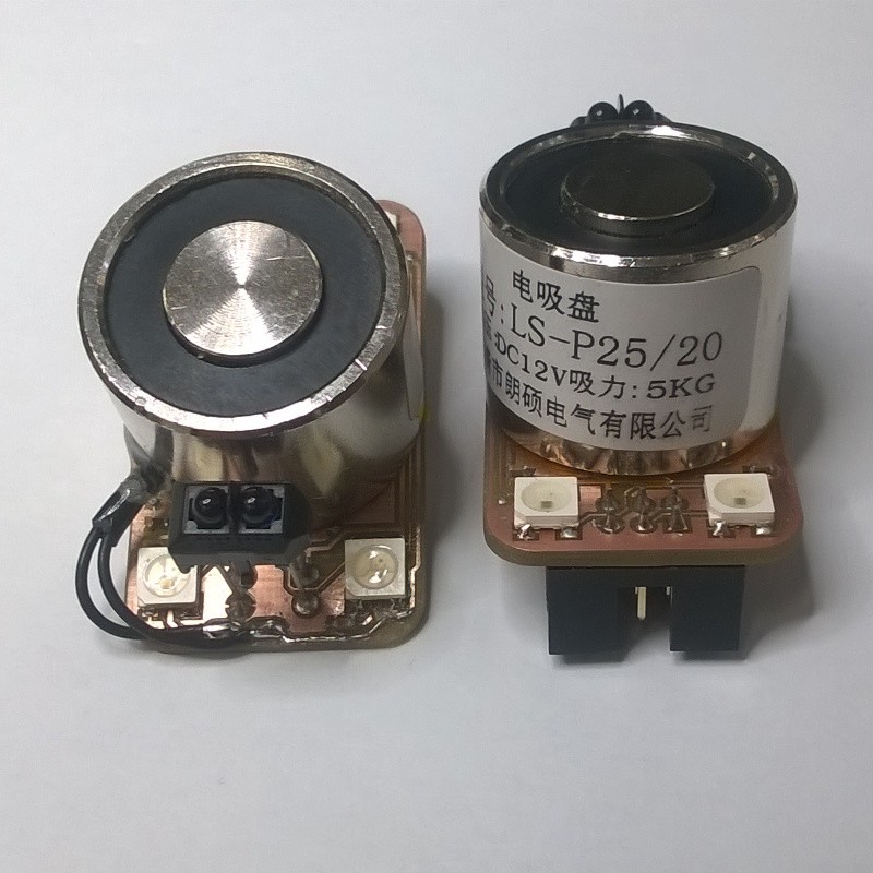
06/02/2018 at 18:54 • 0 commentsPictures below show assembled PCBs. All components can be soldered using only soldering iron with fine tip. Since my PCBs were milled I had to manually connect vias. Best thing to use is solid core hookup wire. Also there were some traces damaged during milling so they needed to be repaired. All in all it took me 30 minutes to assemble the complete module.
![]()
![]()
![]()
![]()
To ease assembly process I like to mark components I already placed.
![]()
-
Designing and making PCBs
06/02/2018 at 18:45 • 0 commentsPCBs for this project were designed with ease of reproducing in mind. Main goal was to achieve smallest size as possible to reduce the cost of fabrication while still being relatively easy to assemble. Components used are in SOT, SOD, 5050 and 0603 packages. Hardest components to solder are SOT packages because. Switching converter in bigger packages just aren't available. Tight layout of components is necessary to ensure optimal operation of switching converters. 3D preview of the module.
![]()
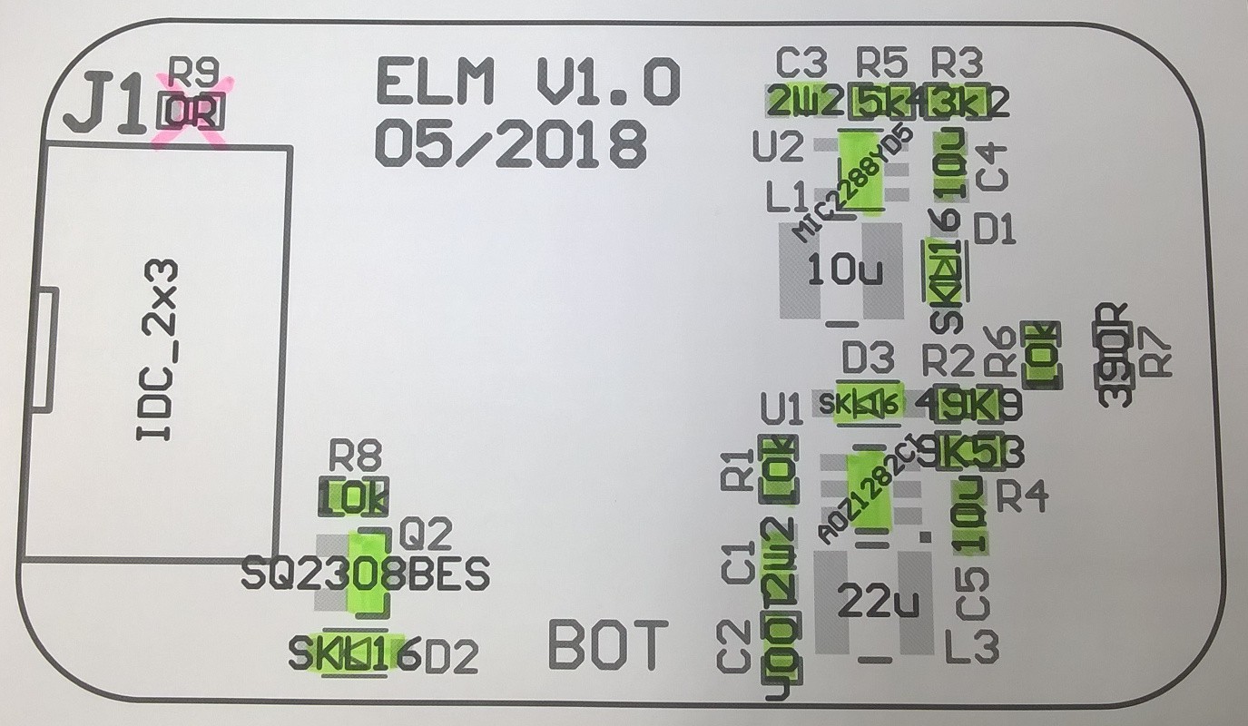
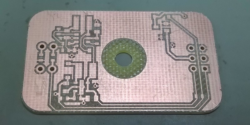
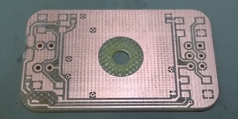
To make assembly process easier assembly drawing is included. Bottom pictures show milled PCB (bottom and top side). Some traces are damaged so I will have to repair them with jumper wire.
![]()
![]()