-
Using Concorde TSP solver
06/10/2018 at 22:18 • 5 commentsIntroduction
Concorde is a cut and branch based exact TSP solver. In other words, the solution from Concorde is the best optimal solution among all feasible one.
However, due to license constraint (see the last license issue section for details), I have to look into an alternative heuristic (approximation) approach later.
Build Concorde
1. Download Concorde source code from here.
2. Download a binary LP solver from here and deploy the header and static library into ./QS64_linux or ./QS64_darwin sub folder under Concorde source code depending on your platform.
3. Build with the following script:
if [ "$1" == "linux" ];
    then
        echo "Build for Linux 64"
        make clean
        ./configure --with-qsopt=$PWD/QS64_linux
        make -j 16
elif [ "$1" == "darwin" ];
    then
        echo "Build for Mac OS X 64"
        make clean
        ./configure --with-qsopt=$PWD/QS64_darwin --host=intel-x86-linux
        make -j 16
else
        echo "Unkown parameters!"
        echo "./build-64.sh [linux|darwin]"
fi
4. If you resolve all other dependencies in your build platform and build it successfully, Concorde binary will reside in ./TSP folder.
PoC
Given entry points and exit points of each part in the layer from output text file, we can use asymmetric traveling salesman problem (ATSP) solver to find out the optimal traveling order of the parts such that air time travel distance is minimal.
If you already build and \play with Concorde, you will find that Concorde seem to only solve TSP, where there is one and only one weighted edge between two vertexes. I have to say Concorde is great except its poor documentation. For last 10 years, its developer's guide is still under construction. You can hardly find a user guide to tell you how to provide input and interpret output.
In any rate, Concorde is free. So stop complaining and poke around this.
After reading its test code, it mentioned TSPLIB, which is TSP solver benchmark data. Google TSPLIB and you will find its data format. I shared the data format specs in the file section. There are two ways to define edge weight in TSP:
1. Define vertex coordinate -- Vertex_Index X_coordinate Y_coordinate.
2. Define edge weight matrix. If the matrix is not symmetric, you turn Concorde from solving TSP into ATSP
See TSPLIB tsp input data here.
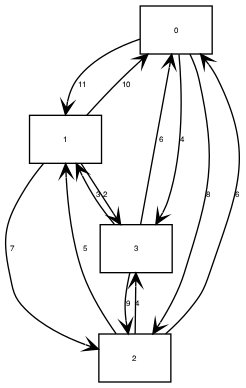
So I manually write a trivial case to do a PoC. See the diagram below generated by dot file and the in and out of Concorde.
![]()
TSPLIB format input:
Ricky@imac:~/repo/concorde/SAMPLES$ cat 4point.tsp
NAME:  demo
TYPE: TSP
COMMENT: 4 vertexes asymmetric problem
DIMENSION:  4
EDGE_WEIGHT_TYPE: EXPLICIT
EDGE_WEIGHT_FORMAT: FULL_MATRIX
EDGE_WEIGHT_SECTION
9999 11 8 4
10 9999 7 2
6 5 9999 4
6 3 9 9999
EOF
Concorde output:
Ricky@imac:~/repo/concorde/TSP$ ./concorde ../SAMPLES/4point.tsp
./concorde ../SAMPLES/4point.tsp
Host: imac  Current process id: 96043
Using random seed 1528799254
Problem Name: demo
Problem Type: TSP
4 vertexes asymmetric problem
Number of Nodes: 4
Explicit Lengths (CC_MATRIXNORM)
Optimal Solution: 21.00
Total Running Time: 0.00 (seconds)

Ricky@imac:~/repo/concorde/TSP$ cat 4point.sol
4
0 2 1 3
Concorde deliver the optimal tour 0 => 2 => 1 => 3 => 0 with optimal cost 21.
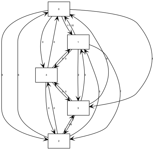
For our path planning purpose, we don't need a tour that comes back to the original point. One trick I made is to add a facilitated vertex where its in and out edge weight is zero and connect to all other vertexes.
![]()
Augmented Concorde Input:
Ricky@imac:~/repo/concorde/SAMPLES$ cat 4point_extended.tsp
NAME:  demo
TYPE: TSP
COMMENT: 4 vertexes asymmetric problem
DIMENSION:  5
EDGE_WEIGHT_TYPE: EXPLICIT
EDGE_WEIGHT_FORMAT: FULL_MATRIX
EDGE_WEIGHT_SECTION
9999 11 8 4 0
10 9999 7 2 0
6 5 9999 4 0
6 3 9 9999 0
0 0 0 0 9999
EOF
Augmented Concorde Output:Ricky@imac:~/repo/concorde/TSP$ ./concorde ../SAMPLES/4point_extended.tsp ./concorde ../SAMPLES/4point_extended.tsp Host: imac Current process id: 97242 Using random seed 1528804704 Problem Name: demo Problem Type: TSP 4 vertexes asymmetric problem Number of Nodes: 5 Explicit Lengths (CC_MATRIXNORM) Optimal Solution: 13.00 Total Running Time: 0.00 (seconds) Ricky@imac:~/repo/concorde/TSP$ cat 4point_extended.sol 5 0 4 2 1 3By removing the facilitated vertex 4, we got a path 2 => 1 => 3 => 0 with optimal cost 13.
Converter
Writing a converter is a piece of cake in Python. We have X and Y coordinate of all entry point and exit point of parts. Compute its Euclidian distance, generate the asymmetric weight matrix and then add a facilitated vertex. Then our converter is done.
[Work-in-progress]
License Issue
I shoot an email to Prof William Cook, who owns Concorde and co-authors the great TSP book, and ask if I can use Concorde under GPL. He suggest to make use of Concorde as my hobby project, instead of GPL. I respect that. After reviewing Concorde source code, you will be amazed how many years of experience and intelligence built in that implementation.
I don't think I have bandwidth or enough intelligence to build a TSP solver from ground up. He pointed me to implement TSP in a simple heuristic approach -- 3-opt (k-opt) approach. I will look into that as I'm writing this log.
-
Data! Data!! Data!!!
06/08/2018 at 11:51 • 0 commentsSolver
From open source to proprietary, there are tons of traveling salesman problem (TSP) solver available.
In operation research, TSP is one of mixed linear integer programming (MILP) problem. Compared to linear programming (LP), the search space of MILP is discrete. Thus, it is NPC problem in complexity theory. In English, for such problem we haven't found an efficient algorithm that can solve the problem in polynomial time.
To grasp the intuition what NPC is, let me give you an example. Let say we have N=64 switches, whose state can be either on or off. We have different real number outcome given the on/off combination of all 64 switches. Your goal is to try to find a combination such that it delivers a whatever optimal function you prefer. There are 2^64 combinations! That's 20 of zeros in 2^64. If you use brute force search on its solution space, chances are you may not get your answer until the end of universe. Let say you can tests at the speed of 1000 combination per seconds, you need approximate 10, 000 billion years.
MILP problem is similar to the example I gave above. Although the problem seems to be impossible to solve within reasonable time in theory, it is not exactly the case in practice. Depending on the nature of the problem, we may be able to find an intelligent method to cut the search space so that reduce the number of candidate in dramatical manner.
In the last 30 years, MILP is a hot research topic. With algorithm improvement and beefy computer hardware, we can solve a lot of MILP problem by computer. The Traveling Salesman Problem book [1] gave a good survey on this topic. I borrowed it from NCSU library and read it as I wrote this log. The book is well written and easy to understand even for operation research outsider like me.
Data
We kind of know the approach to solve the problem. But we need data.
Most of the time at work, acquiring data is always more challenge than solving the problem itself. I'm not kidding. Data is asset to any company but not the algorithm. Google can publish or even open source its page rank algorithm without losing its technological advantage to others. Because very few company has such large volume of user data.
In part order optimization, the related data is right in the Cura slicing pipe line. To extract them, requiring some time and effort to understand Cura source code. I spent two weekend in doing this. To save your time, I wrote a developer guide and shared my source code notes.
In my modification, I output three text files:
1. parts data file.
2. entry point and exit point of part data file.
3. parts optimized order data file.
For more details, please check out my wiki.
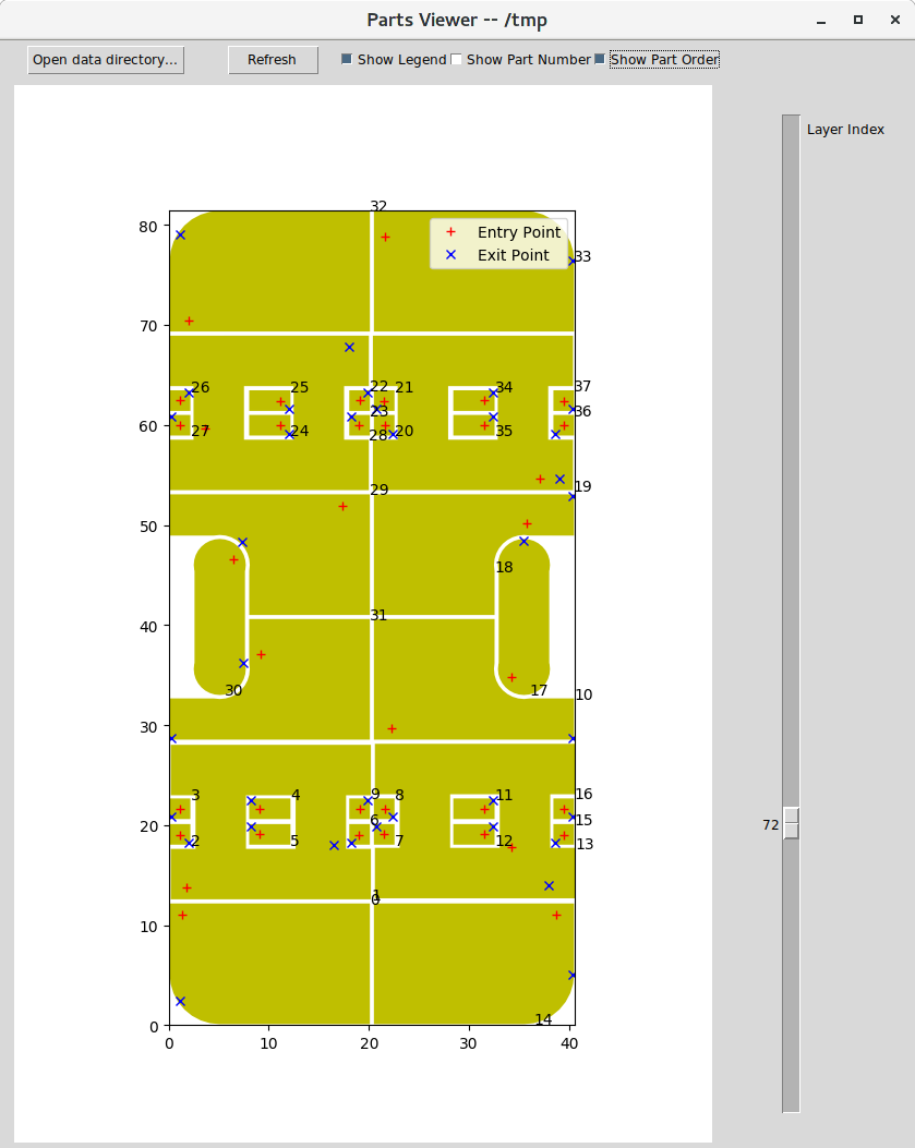
I also wrote a matplotlib TKinter UI to visualize all three data files. The drawing algorithm is quite interesting. Because for any part, there might contain more than one closed polygons. The first closed polygon is its outer perimeter. Any closed polygons other than the first one are the empty space of parts. Although a part is defined as a closed polygon has no overlap with any other part, it is possible that other part reside in the empty space of parts. To make the drawing right, we need to perform topological sort on part. Any part that reside in the empty space of other parts needs to draw after other parts being drew. Otherwise, drawing empty space (i.e. filling in a white color) will cover those parts.
In any case, here is what you got in the end. I did a few sampling test. The entry point and the exit point matched the tool path simulation in the latest Cura. From here, I will study the TSP academic book and work on implementation.
![]()
Reference
1. The Traveling Salesman Problem - A Computation Study. David Applegate and etc. Princeton University Press. 2006
-
Problem Statement
06/07/2018 at 02:17 • 0 commentsThis log documents three questions: what, why and how in tool path planning.
Note that if you are not clear the 3D printing terminology used in the log, please refer to glossary here.
What
Most of the time the "what" is more important than the rest of questions. In fact, it took me quite some time to ask the right/good question in tool path optimization. This is due to the fact that my understanding of slicing algorithm started from zero on May 4th 2018.
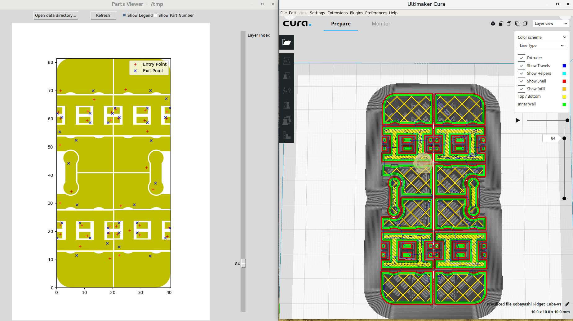
Slicing engine for FDM printing is quite new. There are tons of room for further improvement. My project focus point is tool path optimization for parts (a.k.a islands). A part is a closed polygon that have no overlap with another closed polygons in the 2D layer. See photo below is the 84th layer of a popular STL model fidget cube. The parts includes insets, infills and top/bottom layers (I hate using term but I have to, please check the glossary).
Each part has their an entry point and an exit point. In slicer, you can change the printing order of insets and infills. Thus, change its entry point, exit point and part order. But god knows how they figure out the entry point of each part. I'm pretty sure they are sub par choice for the most of the time.
But for the time being. Let's solve one problem at at time. My problem statement is that find the optimized part travel order so that air travel distance is minimal.
![]()
Why
The 'what' in previous section seems to be easy to understand. But again, I want to tell you that it is the most difficult question. No kidding.
To answer why is easy. Because life is short. If you can save average 10 seconds in each layer by path optimization and there are 200 layers in slicing, do your math you will be amazed how many minutes you can save due to optimizer.In addition, the print quality may improve as well. Because less air time travel means less retraction and less messy stringy...
How
In theory, this is an asymmetric travelling salesman problem. Every computer science kid will tell you this is NPC problem in their complexity text book. In English term, it is a problem that can't be solved by a Turing computer easily.
In reality, we can SOLVE TSP with reasonable size easily. Up to 2018 -- operation research scientists have made a tremendous progress in designing and implementing mixed integer linear programming solver. In addition, improvement in beefy computation hardware also help solve the problem which was impossible to solve in the past.
I personally do a test in the best TSP solver in human history called Concorde. It can solve a complete graph with 1000 vertexes withing 5 seconds on my Intel Sandy Bridge i7 box.
So far I have output parts data and entry point and exit point of part into text file. The next step is to design and implement a solver.
-
A journey of a thousand miles begins with a single step
06/03/2018 at 10:09 • 0 commentsBackground
Because I got frustrated at the frame design of hexapod I worked on, I started to look into different approach: design and build parts in 3D printer by myself. That's how I start my addiction to 3D printing.
I bought an entry level 3D printer, used Fusion 360 to design parts and then ran open source slicing engine called Cura to generate G code. But from time to time, I got so frustrated at the print quality of the parts I designed.
At the first sight, I'd blame my 3D printer. But in fact it is not my 3D printer's fault even though it is cheap. It did do an amazing job in some print. One of major source of the low quality print usually comes from sub par 3D printing path. My conclusion comes from my observation of irrational (crazy) physical move of nozzle and also benchmark test on different version of Cura.
So who generate that sub par tool path ? Well, it is slicing engine, a.k.a slicer.I'm an analytical software developer. I tried to figure out the way to improve it. So I quickly pick up the general idea of software stack in consumer grade FDM based 3D printing.
From triangle mesh to G Code is done by slicer. From G Code to physical motion is done by firmware in 3D printer.
I'm an advocate of freedom software. The slicer Cura is open source. Perhaps I can contribute back with my expertise.
What's next
First, I need to get some basic understanding of slicing engine pipeline from this SIGGRAPH lecture. Then I cloned Cura repo into my home server and read their source code with cross referencing software called lxr.
I published my source code study notes on my Github wiki.
The more I read in Cura source code, the more I understand the importance of slicer in 3D printing. As I said before, I'm an advocate of freedom software. I personally believe that any open source software project should not be owned nor dictated by any hardware company whose sole interest is to promote their hardware sales. Cura engine is a good case in point. It is back by Ultimaker a 3D printer company in Netherland.
I'm not against any for-profit company like FSF. But I just don't feel comfortable with this. There is a serious ethical problem here that complicates the whole thing.
In any case, I forked Cura engine in github and started to work on tool path planning improvement on my own in a complete different branch. That's how this hackaday project starts.
 Ricky Zhang


