I admit it! When I designed the BQ25504 breakout board I didn't really understand everything in the data sheet.
I missed the part about keeping the portion of the board with the resistor dividers free of GND pour (this is such a small board this "error" doesn't really seem to matter). I also used a single GND scheme; another violation of the reference design. I didn't clean the resistor divider portion of the board with solvent after production as recommended (are you kidding me?).
The biggest misunderstanding appears to be the role/purpose of Vstor, one of three BQ25504 outputs (Vbat and VbatOK the other two). I labeled this as Vsyst, since I assumed this was the output of the BQ25504 boost converter meant to power the microcontroller or whatever the combination solar cell charger/ LiPo battery was supposed to power.
In fact, the data sheet says of VSTOR:
"Connection for the output of the boost charger, which is typically connected to the system load."
And I have been connecting the SensorTile power input to the Vstor/GND port of the BQ25504 in all of my testing to date. This works fine as long as the battery discharge from use of the SensorTile is the same or more than the battery charge during exposure to sunlight, as was the case last Summer when I was doing initial testing during cloudy or smoky days.
What I have discovered this Summer with longer hours of direct sunlight, is that when the battery is fully charged (and the boost converter output exceeds the battery overvoltage threshold), Vsyst is turned off! This means the system load stops working, which is a bad thing (see previous log)!
The solution is pretty simple. I removed the SensorTile input wire from Vstor and soldered the lead to Vbat. Now even if the battery full threshold is crossed and Vstor (formerly Vsyst) is shut off, the SensorTile itself will keep going and eventually the battery will run down sufficiently that the boost converter wll start up again when the sunlight returns, ad infinitum.
So it seems the BQ25504 is supposed to have two power storage media, one connected to Vstor and one connected to Vbat. I am still a bit confused by this. What is the idea here, connect two batteries to the BQ25504, or connect a supercap to Vstor and a LiPo battery to Vbat?
Right now I am in the middle of another SensorTile power test where I have connected a 105 mAH LiPo battery to Vbat/GND, connected the SensorTile input to Vbat also, and left Vstor unconnected. This seems to work fine and I am now 34 hours into the test with the battery charge state oscillating between 84% (at 10 AM, local device "sunrise") and 94% (at 2 PM, local device "sunset").

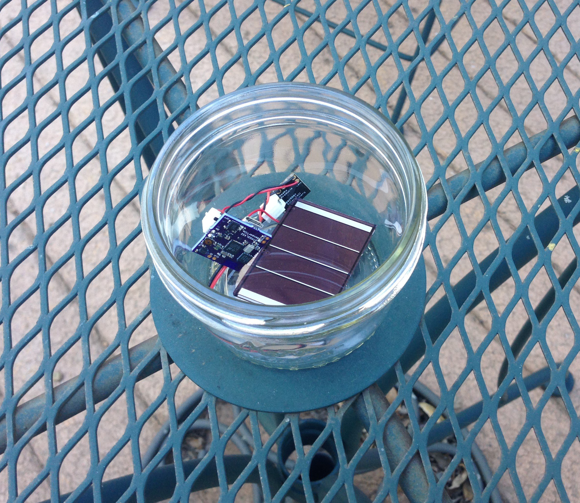
This is the current experiment: SensorTile, BQ25504, 105 mAH LiPo battery, and 50-mm-long solar cell in a glass jar on a cast-iron table out on my back deck where it enjoys ~4 hours of direct sun.
I am keeping track of progress via BLE and I will report on the results in a few days (assuming the SensorTile doesn't conk out again!).
Now, maybe the dozens of people who have bought and are using the BQ25504 SolarCell LiPo Battery Charger from Tindie for their own projects already know how to use it properly. It's embarrassing to say after a year of playing with this device that maybe I have just learned how it is supposed to work too!
Now that I seem to have gotten the solar cell energy harvesting sorted out, I thought I would give Peltier junctions a try. The BQ25504 accepts energy inputs as low as 330 mV.
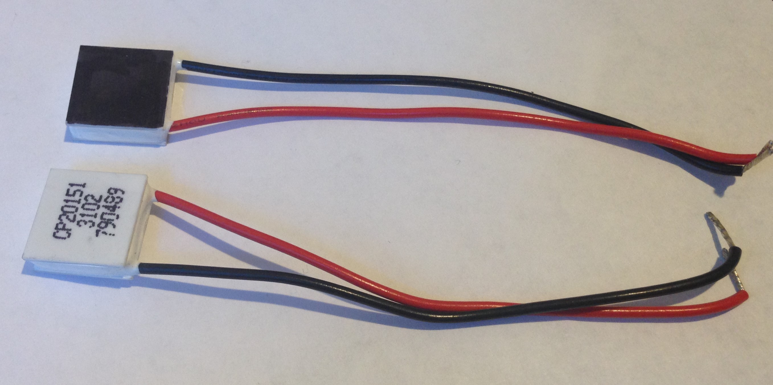
Not knowing much about Peltier junctions (never stopped me before!) I selected the CP20151 made by CUI, Inc. Now these devices are intended to be powered in order to produce a temperature difference typically for localized cooling applications. And the data sheet specs quote the amount of temperature difference produced between the cold and hot sides of the junction for given voltage and current input.
Well, I am proposing to do just the opposite. Namely, use an existing thermal gradient to drive a voltage and current. I am not even sure this will work, or if I have chosen the appropriate Peltier junctions for this to work well.

I blackened the hot side with permanent marker thinking I could simply substitute the Peltier junction for the solar cell and use the black side to absorb sunlight and heat up and keep the cold side facing away from the sun (maybe laying on the cast-iron table to wick away any heat).
I haven't tried this experiment yet, being preoccupied with the mystery of the conked-out SensorTile. But I did place the hot side of the Peltier junction on a hot plate at ~100 C and measure the voltage developed across the black and red wires ---~100 mV :<
I am not sure this is going to work.
 Kris Winer
Discussions
Become a Hackaday.io Member
Create an account to leave a comment. Already have an account? Log In.
Maybe, but I have had pretty good results with a direct connection and as long as there are a few hours of sunlight per day the system is stable. The end node I chose for the tests uses ~1 mA and a 105 mAH LiPo plus 20 mm 3 V solar cell keeps it going forever with three or four hours of sunlight per day. So my point here is this works well.
Now if I needed to add a capacitor in order to make use of VSTOR as system load provider, the capacitance would have to be what, ~1 mA x 30 seconds, or so? Maybe 5 nAH would do it, this is a pretty large capacitor...
Are you sure? yes | no
Kris, you should not connect system load directly to a LiPo battery. You will deep discharge and can eventually cause a catastrophic event. You need to look at the system load and size an appropriate capacitor so that your load continues to be powered while Vstor output cycles between hysteresis limits. The datasheet has one such example. Let the bq25504 manage the OV and UV limits of the battery for the safest operation. You may end up with too much of a draw on the battery and result in discharging it below it's UV limit causing a breakdown.
Are you sure? yes | no