-
1Step 1
General Details for the Tracker Frame Assembly
The solar panel frame is built in three sections:-
- The Ground Post. This is a 6 feet length of 2" steel or aluminium. If your local weather tends to be a bit stormy, you might consider incerasing this to a 4" post for added stability. Take 3 of the 4 inch hinges and mark out their positions as per the drawing in the FILES section - basically , you will need around 3 to 4 feet of post buried in the ground, so space the 3 hinges one o the top of the post, one just above ground level and one in the middle. Mark the hole centres for the hinge mounting holes and drill all the way through the post. Take the 3 inch stainless steel M4, countersunk bolts and push them one at a time through the hinges and the post and secure them on the other side of the post using M5, locking stainless steel nylon locking nuts. Repeat for all three hinges.
- Pre-Make the rotator head. Follow the drawing in the FILES section and either weld or bolt a length of 2" steel or aluminium angle to the length of 2" post. Weld or bolt 2 stiffening struts to secure the 2" angle.
- Take the 10 ft length of 2" steel/aluminium box section and marry it up with the rotator head angle section that you've made above in section (2) then mark out and drill the mounting holes through both sections. It's best to clamp the two together to make sure that all of the holes end up lining up.
- Hammer or bury the ground post into the ground in the position that you want your panels to be. Ensure that it goes in vertically by using a spirit level. Make sure that post is align to true North/South - just use Google Earth to pick a spot that lies on the line to true South from your solar panel position. The hinge holes that pre-drilled to hold the rotator head should be pointing due West - that's true west, not magnetic west. If Your pole is properly aligned, then this will already be the case. The software will compensate for your alignment not being perfect, but the more accurately it is set, the better.
- The rotator assembly. Attach the rotator head to the ground post with the hinges that you've already attached - mark out the hinge mounting holes and drill through the rotator 2 inch box section, then use 75mm countersunk stainless bolts + nuts to tightly secure it to the ground post. You now have a rotatable mounting for the elevation bar.
- Use some 1 inch (25mm) stainless steel, countersunk head bolts to attach 5 of your 4 inch stainless steel hinges to the elevator bar - this is the 10 ft length of 2 inch aluminium/steel flat bar. The hinges are evenly spaced along the length. Drill the matching hinge holes on the main rotator bar (the 10'/3m length of 2"/50mm holow section) and attach the elevator bar using the hinges that you just attached. You should now have a 10'/3m , hinged elevator bar.
- Attach the linear actuator mounting brackets and linear actuators as per the drawings - don't forget to put on the rubber gaiters to cover the linear actuator extension arms for weather protection.
- Attach the elevator bar to the rotator head that you attached to the ground post above and you now have a solar tracking array capable of rotating 3 solar panels to track the sun
-
2Hanging The Solar Panels
Ideally, the solar panels need to hang on the tracking array so that they have a neutral weight on the elevation adjustment hinges. So, I have made some simple hooks out of some of the offcuts of flat, 2" bar used to make the elevator bar and the rotator head stiffening struts.
Cut two x 2 inch lengths of metal and 2 x 4 inch lenthgs. The short length is just a spacer and the long length is the hook. Mark the back of your solar panel so that when it is hung onto the elevator bar, it's centre of gravity (i.e. the mid-point) is aligned with the elevator bar hinges. Carefully pre-drill holes through the two x 2 inch bars into the aluminium frame of each solar panel and secure with 25mm/1" stainless steel bolts.
I found it re-assuring to put abit of metal bar under the solar panel drame that I was drilling to protect the solar panel as I had nightmares about drilling through and damaging the glass bit of the panel and thereby rendering it pretty useless.
There's a drawing of this in the files section
Hang the first panel centrally on the elevator bar and then drill an attachment hole through the stiffening frame and into the aluminium frame of the solar panel and attache the two with a 25mm/1" bolt.
-
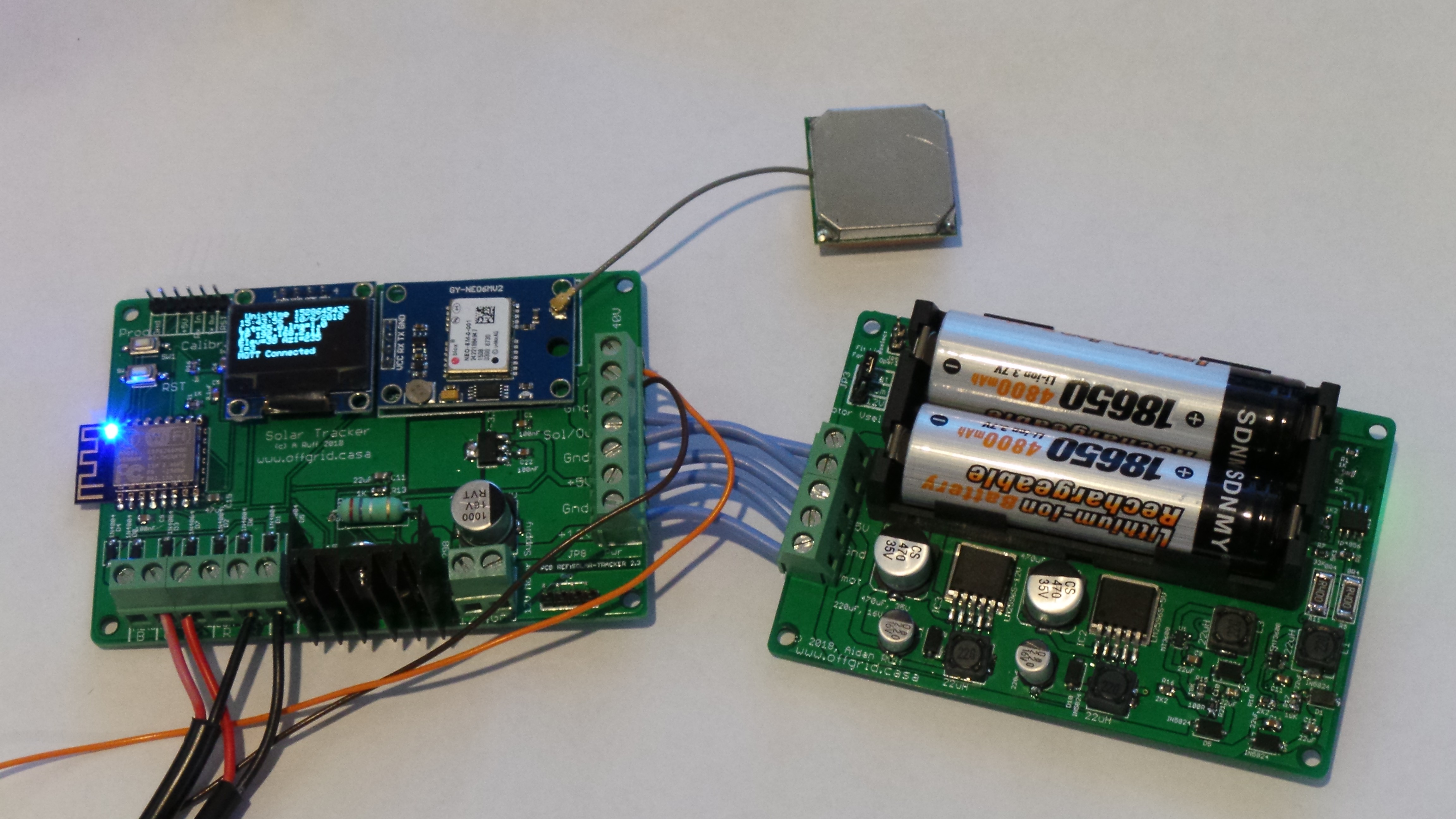
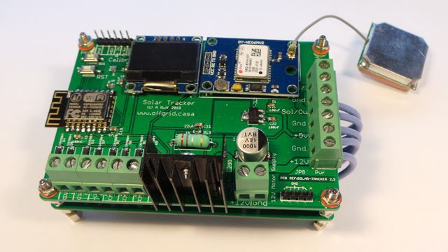
3Solar Tracker Electronics
![]()
![]()
In the FILES section, you will find all of the files necessary to sendoff to a PCB manufacturer. I have been using jlcpcb.com for about 18 months and they have a fast, reliable service. Order both the the controll PCB and the charger/power supply PCB at the same time and you will get them both delivered in about a week using DHL delivery for around $35.
Just start an order and upload both ZIPPED sets of GERBER files and the PCB manufacturer will do the rest.
GPS RECEIVER. You can either use the cheapie ($1.50) version or the more expensive $5 version which I used. For 5 bucks, you get a more sensitive receiver with a larger antenna, which may help if you have geography blockin the satellite signals in your area.
IN the picture above, you can see how the two PCBs are interconnected. There are three motor control outputs - I was originally only going to use elevation control, so the unit would control three linear actuators. However, adding the azimuth control to track the sun horizontally as well as vertically, only requires 2 of the outputs.
The two boards can be joined using PCB mounting posts if you want. The connections will then line up so that you can interconnect the power from the charger/Power supply to the tracking control PCB.
I've used 2 18650 li-ion batteries which claim to be 4800maH, however, after checking them on a power monitor it turns out that they are actually only 2000maH. This is common on low cost li-ion available on Ebay...they're just re-packaged, low cost batteries sold at a higher price, so be careful. On the other hand, you only need about 500maH fully charged to run the electronics overnight, so cheapie batteries are in fact fine.
-
4Solar Power Monitor
In the FILES section, there is schematic showing how to interconnet the ATMEGA1284 based power monitor/inverter PCB with the 8 way current monitor.
The power montor board has an RS232 interface which will communicate and control an MPPSolad PIP4048 off grid inverter/charger. It will also monitor up to 4 of the 8 way current monitors and the overall solar array voltage which will give an overall power reading for your solar power system.
The individual soalr arrays output is passed through the 8 way current monitors so that the system knows exactly what each array is generating. Solar panels have isolation diodes so that they won't interact woth each other so it's possible to read the current from each one. In this way, you can check to see what is being generates and determine of any of your arrays is faulty
Solar Tracker, self powered and auto aligning
2-Axis solar tracker interfaces to a power monitor and charger/inverter
Discussions
Become a Hackaday.io Member
Create an account to leave a comment. Already have an account? Log In.