Roddy "Rags" Read
-
How to Break your Kite Turbines
04/27/2022 at 12:57 • 0 commentsFlying a Kite Turbine looks a breeze on some of my videos.
There's nowhere better to be than a warm kite test field with a good wind...
And with the motivation of maybe making a massively scalable and much cleaner energy solution... Why wouldn't you do this?
In this Project Log Entry, I'm going to try put you off making a Kite turbine.
It's not always fun and games.
Making a mechanically autonomous Kite Turbine by prototyping came with a lot of mistakes and crashes.
We tested ~70 variations
![]()
As you can see, a lot of these models weren't perfectly balanced and neat. That, combined with - flying in turbulent wind fields, combined with the energy transmission and generation interfacing, combined with the mix of lifting and generating kite types... It wasn't always easy.
But they have come a long way.
And I still crash themA TV crew was on site to show this crash.
Usually if you're going to goof up it's because you don't have a strong and steady lift kite.
That's the first thing you launch and first thing you should test. I'd suggest steady 10kg line pull minimum.
This is the main reason we have to move to automation . . . It's too easy after laying everything out on the ground to convince yourself there enough wind in the small lifter you launched. doh.
If you want to be safer and you have time and a spare windsurf mast... This won't crash and it's handy for power testing ... But the mast bit won't scale well so it's not where my focus is.
Can still be scary testing on a mast if you're in the wrong spot
Again, if the lifter kite is low tension... Even if the turbine doesn't crash , the turbine head bearing could twist the backline...
At the other end of the spectrum of crash types - TOO MUCH POWER
You'll have noticed we're transmitting torque axially along a set of rotating lines which are held apart by rings.
That's all a bit novel.
If you have this turbine spinning at high speed and your control system is asking too much of the regeneration current when a Lull or gust hits... This is my favourite warning video. You do get to see one huge safety advantage of the backline here
-
Couple test vids
09/26/2018 at 15:44 • 0 commentsOh man there was like no wind in Austria... But it did limp round and make a wee bit of power...
Thankfully it all cam home in 1 piece
This video was one of the Scouts prototypesand this is testing later on with a rigid blade set.
-
Saving weight in packaging
07/18/2018 at 07:17 • 0 commentsOn all previous models, the lower, smallest hoops, were made and sewn in to the compression sleeve. This means they were a fixed size radius. Trying to package this is tricky. As seen in my previous logs.
So, I've made a whole new set of rings and lines for the "torque ladder". Every one of the rings now comes apart. The rings are all made with the same 170cm carbon rod. The advantage here is you can now package all of the kites, all of the rods, all of the lines rolled together. They now fit inside tube carrier I made by modifying a pair large extendable poster tubes. (Two larger diameters fit over one smaller diameter central piece)
The lowest 3 rings (nearest the generator) have 1 rod, the next ring has 2 rods, the third ring has 3 rods.
Deployment is easier now, as you can unroll the complete set of torque tube lines and rings. Photos to follow. And the lines have less knots on their way down. The whole thing looks neater.
Like a Daisy run in reverse ... I'm a fan
-
Oh Yeah the kites
07/11/2018 at 14:41 • 0 commentsWith practice I've neatened my old kite turbine designs.
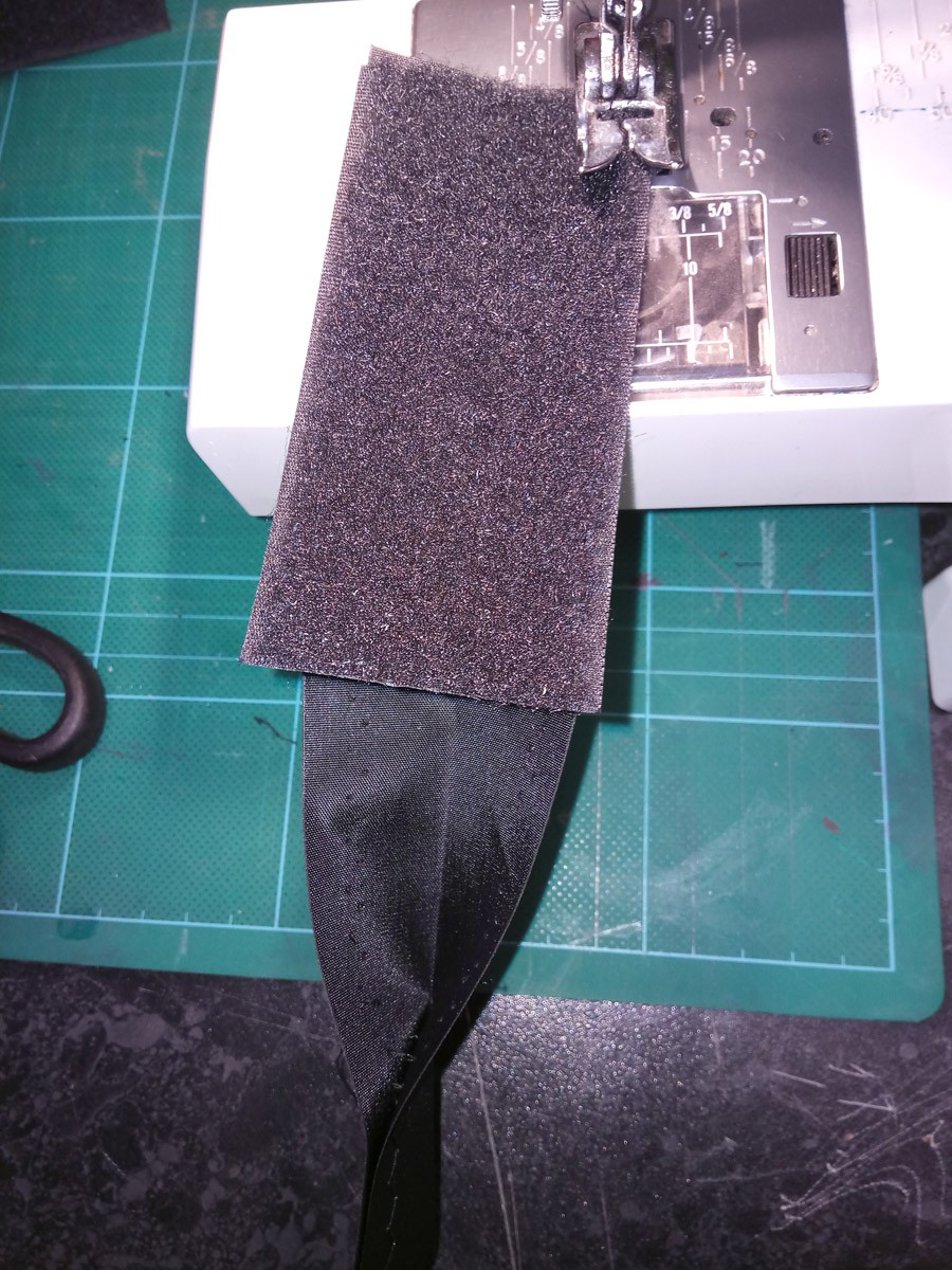
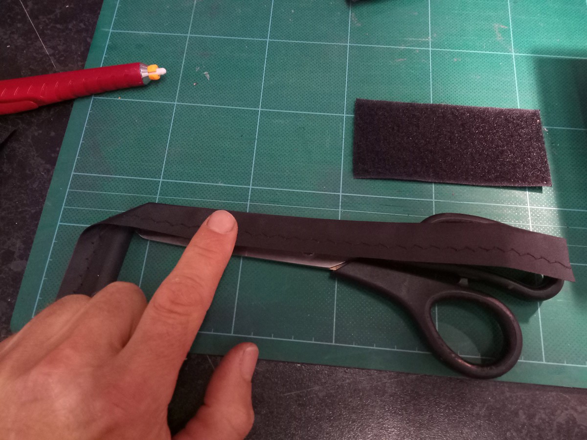
Make neatly cuffed compressed rod rings as follows
![]()
A length of loop inside the end of a compression cuff
![]()
A length of hook over the top past the other end
![]()
This length extra cuff longer than your rod (2 rods or 3 rods) length is great
![]()
The singles, a double and triple rod (1.7m x 4mm carbon epoxy, both ends with heatshrink, one end with a 10cm cuff @ 5cm epoxied in place) into a ring, compressed and closed in a cuff. The single rings have been sewn shut at ~26" ~62cm, Now our minimum packing box dimension.
These rings now need a 6 point harness to a ring in the centre. I made the small white food grade plastic ones, (seen in the boring video) with 3 rim holes for harnessing and a central hole for the central lift line.
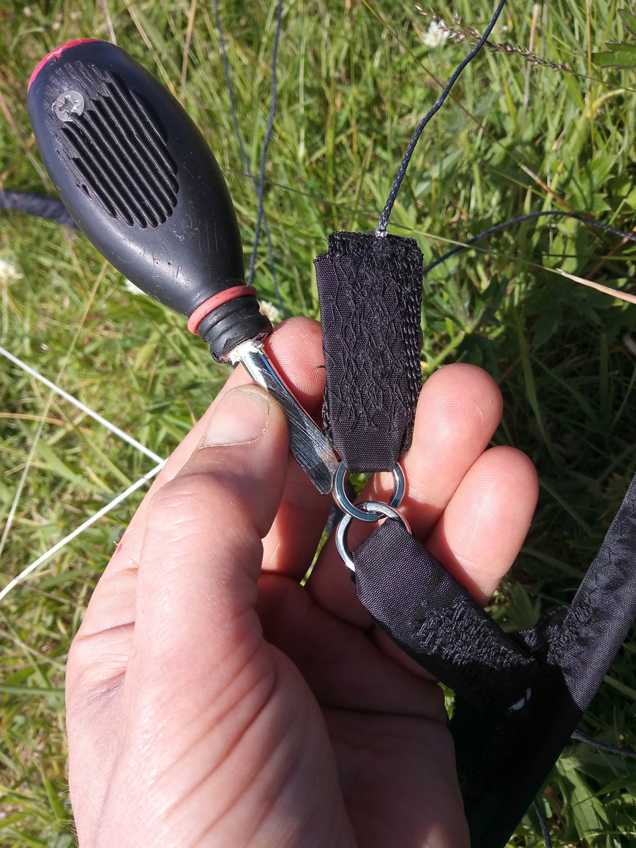
Then you need to add tabs with 6 tethers to rundown the stack from ring to ring.split rings
![]()
The screwdriver blade was sharpened to help opening the strong split rings. The tether at the top comes from the kite, down to the split ring tabs, web supported past the inside of the cuffed ring and on down to the next ring.
![]()
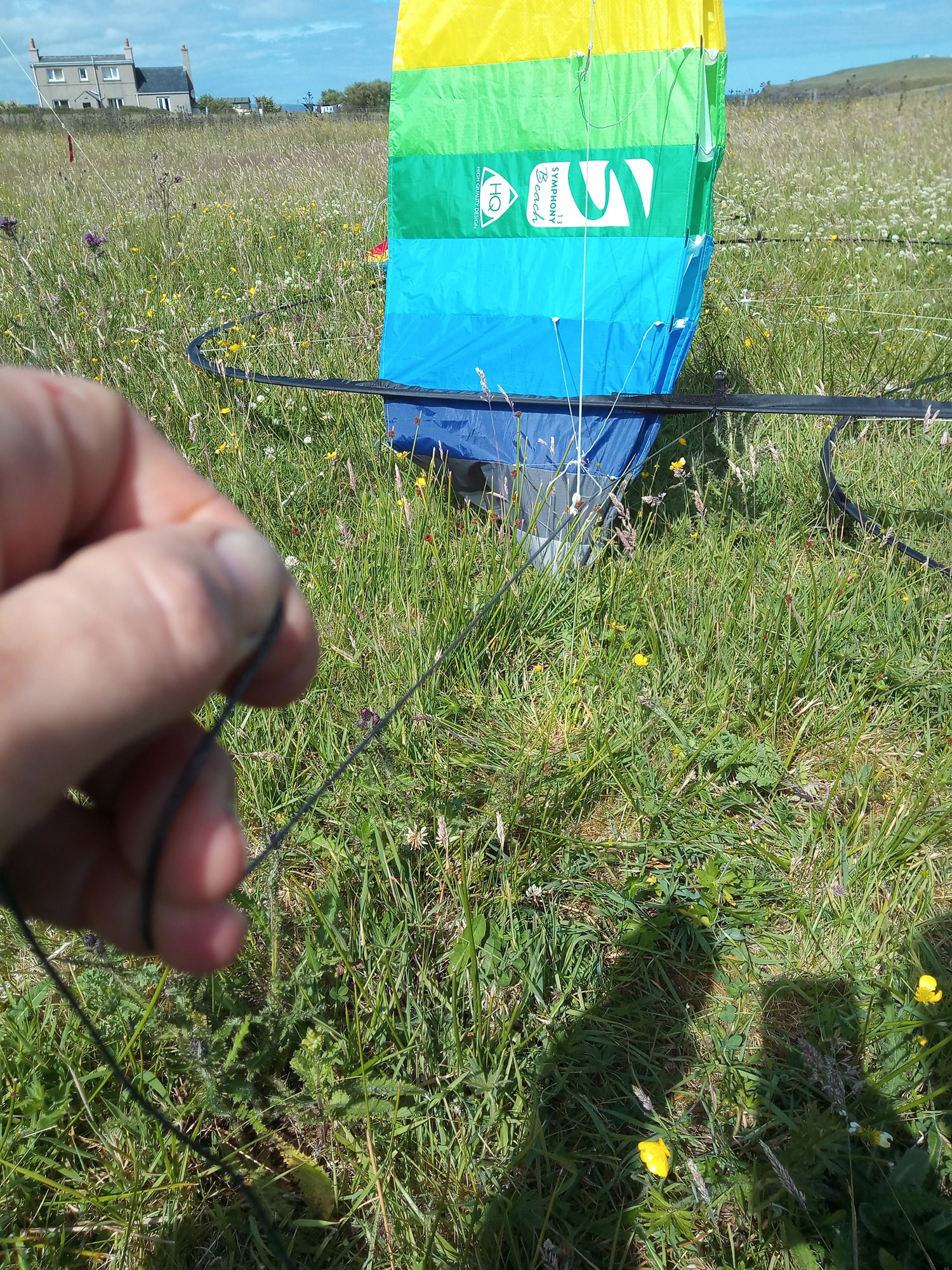
This is the tether from the kite ring. You see a double tab and split ring connection on the ring in front of the kite. That allows the ring kite to fly configured as a single, double, tripple anywhere on a stack of ring kites. Only 3 tethers (black dyneema 2mm 230DaN) come down from this ring. The kite is attached, front and back, to the ring, with webbing strengthening the joins at about 3/4 span. The tether progressively bridles to the kites original bridles. The outermost bridle pair have a longer lead form the main tether. The inside leading edge of the kite has a 3mm epoxy rod to set the leading edge tight.
You're pretty much good to go at this point.
Some young scouts managed to power kettles with it so can you...
Connect everything, throw it in the sky and get power.... well... that'll take a bit of practice yet.
I'll come back soon with more details of how the packing case system progresses.
I may yet change down to a 20" wheel for portability. I also want to make straps so that we can use a wheel which comes off, gets used, then goes back on an e-bike. The battery I use here is from an old motor which has now been incorporated into a powered drift trike. We have used the kite power to run it. But I don't recommend that design..Deadly.
I still have to attach (rivet) the No-Wind cranking handle to the wheel rim ( I want to call it a winding handle since there is no wind) I'd only do this for the scouts camping model as who needs a handle flying round on an actual bike wheel?
I'll let you know how the scouts do on Jamboree.
rod
-
Running, weight loss and flying power success
07/09/2018 at 15:33 • 0 commentsLightweight ground clamp
Thanks to Robbie from Gordon Diesels for designing and making a new post clamp / generator mount. This is magnificently simple. A sheet of aluminium (walkway) cut with a water-jet then folded & welded. The central slot holds a bike motor / generator shaft. Straps hold everything to a post.
Now we have all we need to hold the kites while allowing them to spin fast. Kite torque energy can now be extracted as electrical energy at the generator.
")
Fold the 4 webs and seam weld. (I've added 14 extra suggested hole locations (to this .jpg as splodges) to aid tying off onto flying pole or ground stake architecture. Will try get the cut pattern for you.)
A much nicer running geared hub motor
I also got a new motor from Charlie And Seumas. There was one wire broken in the plug. Not a problem I cut the plug off. Made a wee tig weld on the planetary gear casing. Replaced and tested. All going sweet on VESC 6 test. Packed with grease.. it even has a wheel. Sewed on 6 strap tabs with ropes. Figure 8 stop knot at an equally measured length.
Here's the technicals on getting regen from a bike wheel.
How to put a torque tube together (The boring video)
Wow that was dull, but you did get a look at the kite and torque ladder construction.
Lets go out and test. Finally you get to see flying and clamp v1 in action for the first time in this video.
Finding my fortune on the Shore
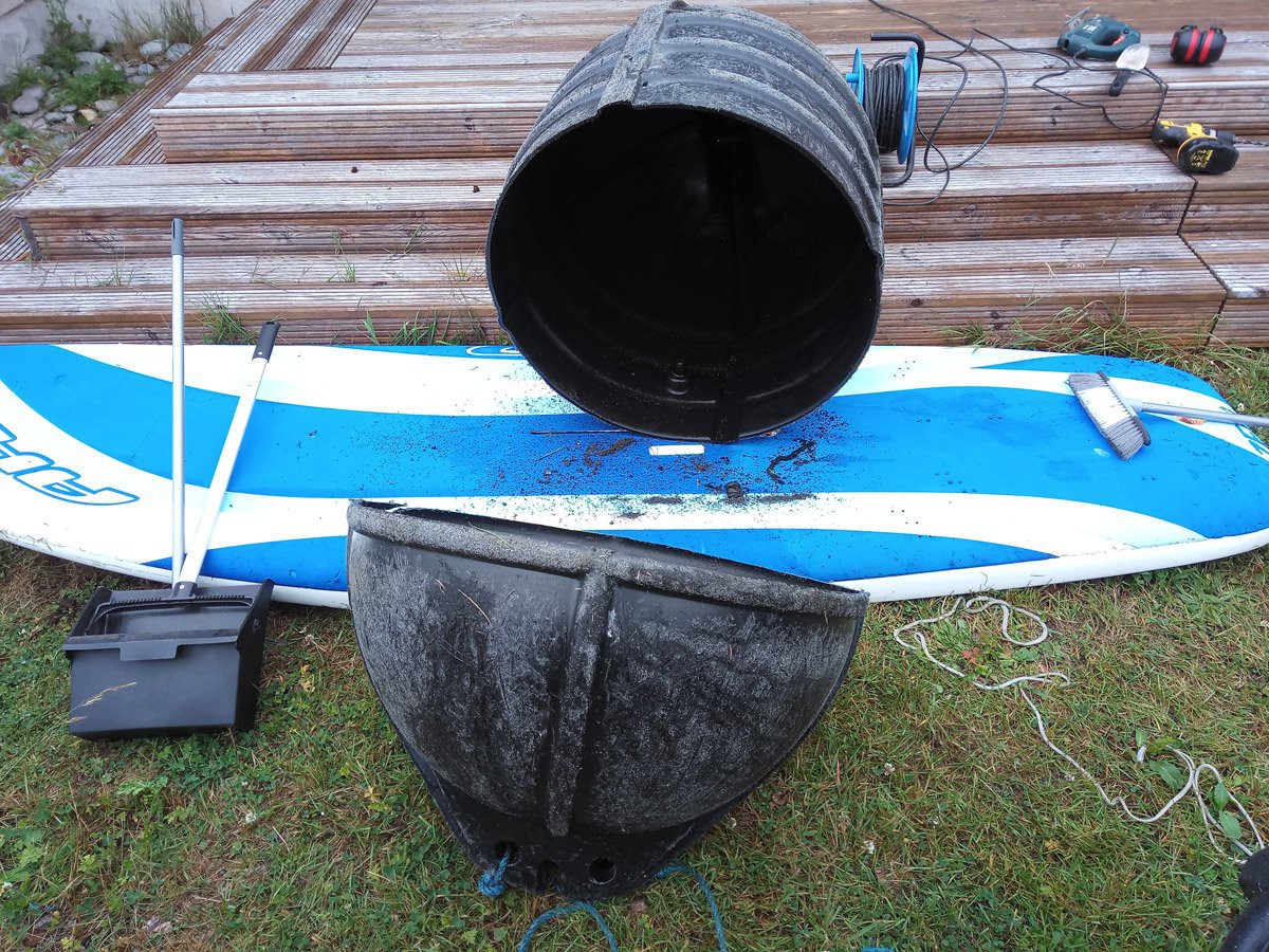
Packaging these turbines and the generation kit for travel is challenging. The smallest rings on the torque ladder are 62cm dia. They don't come apart like the large rings (yet), So somehow we need to protect that for travel. 62cm is big. 62cm is also ~the size of the 26" mountain bike wheel I was given. It's not easy to find standard packaging or storage boxes to fit that. However, if you happen to live on an island with plenty aquaculture, Giant mooring buoys tend to frequently wash up on the shore through the winter. Yes, I had these in my garden.
![]()
You will likely find some other kind of large plastic cylinder (maybe a garden water butt)
If not, first cut enough end off to protect your wheel, rings, motor and gadgets.. then scrub the barnacles off, and remove anything which still smells like an octopuses nightclub. Clean up the plastic sawdust.
-
Initial tests
07/03/2018 at 16:13 • 0 commentsSuccessful Bodging
I bought a nasty old geared hub e-bike motor on ebay. 36V and 36 Spoke. 36V because I have that battery, 36 spoke so I can easily tie 3 or 6 kite lines neatly to the rim.
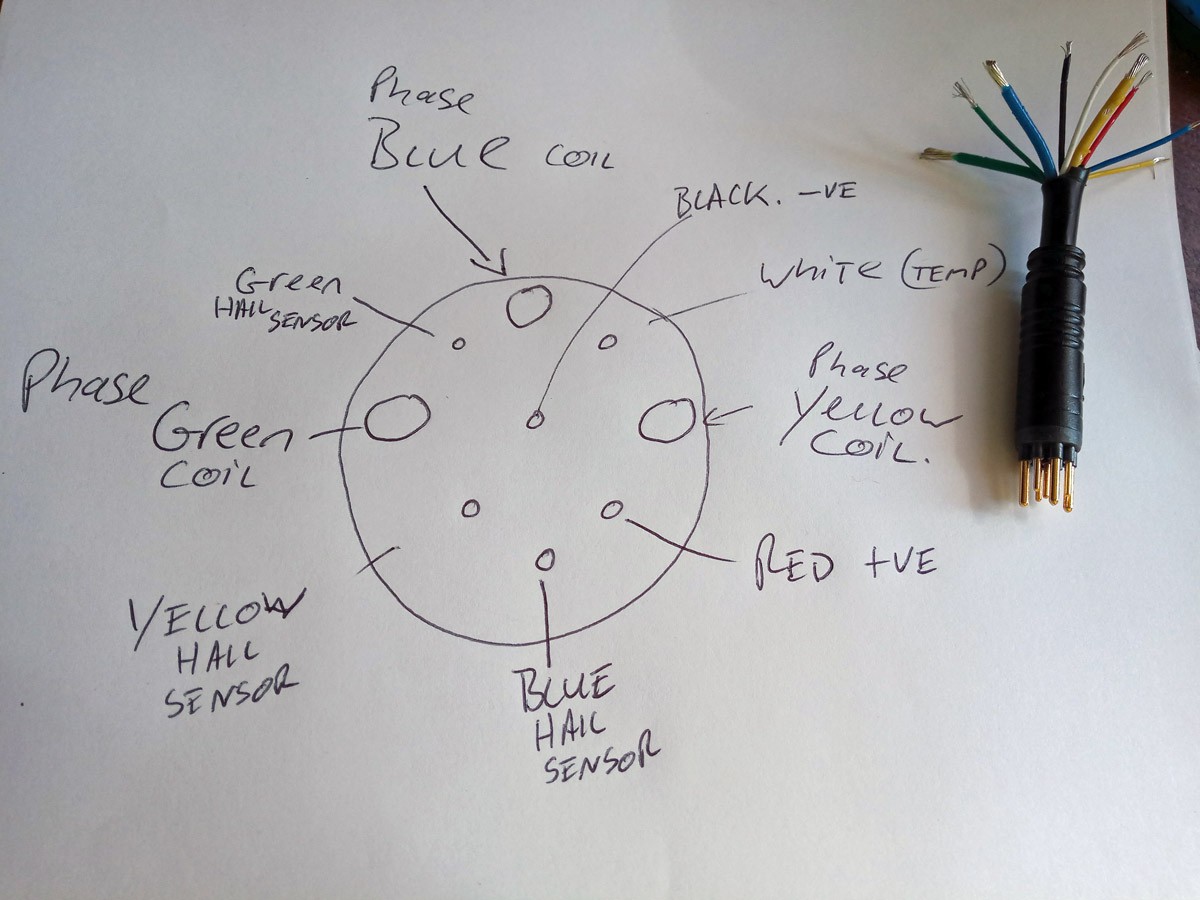
I chopped off the Julet plug, I couldn't find a wiring diagram online and I had no socket. So incase you do have a socket already... Don't bother here's a picture.
![]()
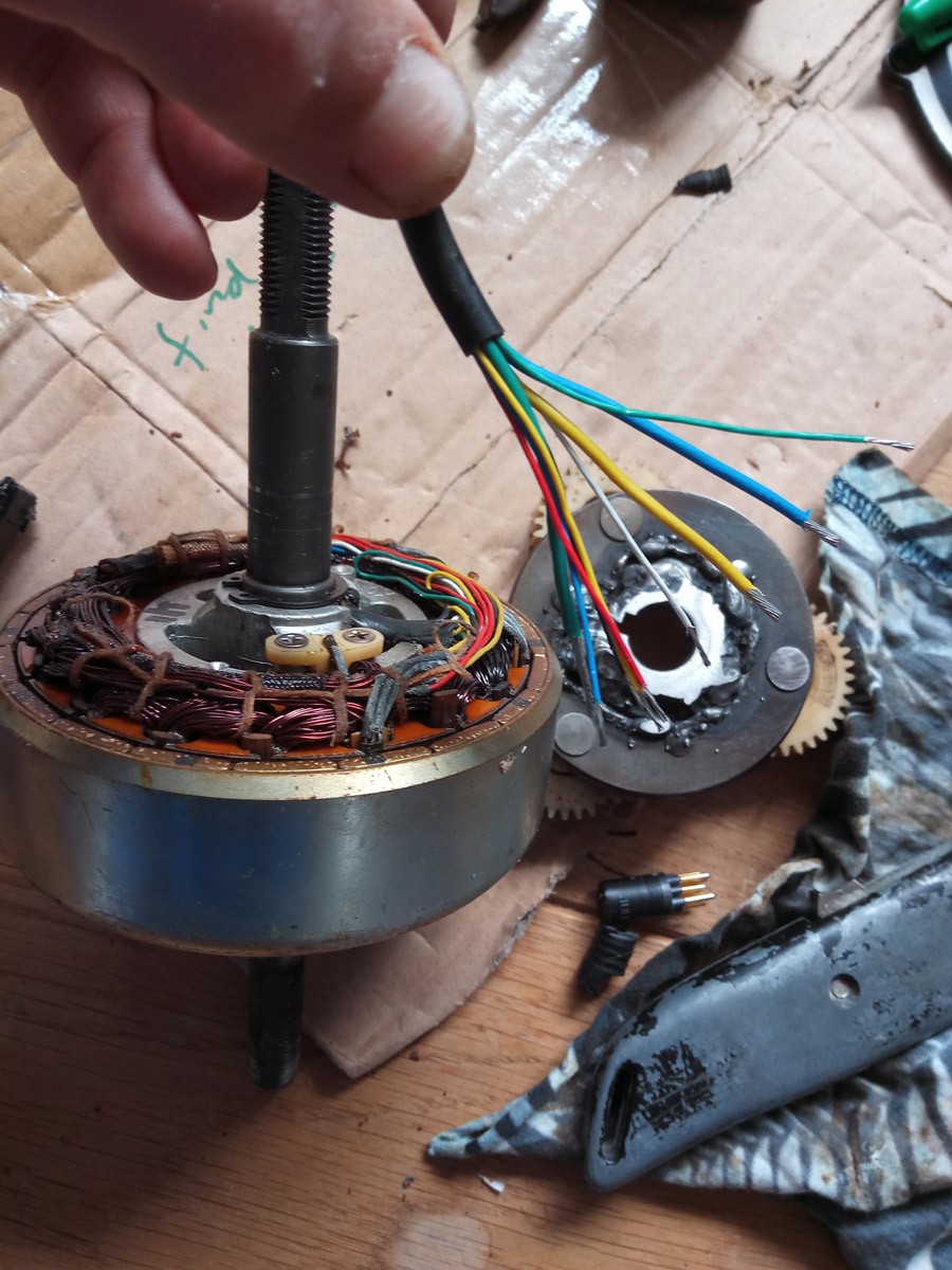
I opened up the motor, blew the ming out and removed the planetary gear to see how I could go about locking it off. As you can see in this photo, I was waaay too brutal with using an arc welder on the thin casing walls of the planetary gear freewheel... I melted the gears a little too. (use a TIG or other small welder)
With disregard for what went where, I hammered (a lot) the messy non-freewheel planetary hub back onto the shaft, and it broke a bit, but it wedged into the motor casing. The whole thing turned with terrible grinding sticking noises.
![]()
Until I connected it to a VESC 6 that is... When it started to sound sweet.
Because you need quality grinding techo sounds pic.twitter.com/P4tGTKa1sP
— Roderick Read (@rodread) June 12, 2018VESC 6 is a phenomenal motor controller designed by Benjamin Vedder and sold by Trampa Boards. It's not cheap. ~£300 GBP. However it's super fast, It walks you through motor setups for Field Oriented Control, It gives you plenty of control interface and motor parameter options to play with. The VESC 4's are open source hardware too.
You can see in the twitter video, I added a thrust bearing (skf 51204) to the motor shaft, this holds the casing from being pulled forward by kite lines and destroying the normal motor housing bearings.
Now find a rusty 26" 36 spoke wheel your neighbor has left outside for ~3 years. Cut it to salvage the rim. I was lucky, my motor came with a set of spokes. I was unlucky, they didn't seem to fit. I made up a spoke pattern so that they did kinda fit and it worked - ish.
If you have to get spokes, using ebikes.ca calculator can help.
The motor and wobbly wheel need held to the ground to hold the kites. We also need the axle to point at the kites but not turn. I rivited a rough u shape section of mild steel to a set of bike handlebars. (keeping with the minimal transport theme.) The steel had a slotted hole cut to fit the flat sections of the shaft. Good enough to hold and generate.
Interested to see how long this survives. Expect work on a standard e-bike wheel and handlebar connector soon. pic.twitter.com/DYvXAjjWmN
— Roderick Read (@rodread) June 20, 2018After a basic wheel truing (see Sheldon Brown for expertise) I attached the 36v Bike battery and VESC6 to the handlebars. I configured the VESC 6 using VESC Tool so the application used a 10kOhm pot connected into the ADC1 of the 8 pin JST connector for speed control. I also set very timid limits to the speed and the current in the VESC Tool software.
Time to tie a kite on pic.twitter.com/nJv2qRTKAH
— Roderick Read (@rodread) June 20, 2018I readied a kite turbine I had lying about... (you likely have to make this bit) We'll cover that in a later project log entry. I also made an extension cable for the battery cause it was very heavy to hold. I fitted a windsurfing harness to the bar... for options. (You can actually run these turbines with the motor as a great big tensile prop...interesting games ahead.)
Complete #AirborneWindEnergy system <10kg ready for scout camp pic.twitter.com/W81LKJpntC
— Roderick Read (@rodread) June 22, 2018I set off to join the scouts for a test. While camping in my van that night, I remembered to reprogram the Arduino mega 2560 R3 equivalent so the regen braking level was proportional to a smoothed factor of speed squared. (Just a best guess at how control should work after a fair bit of experimenting.)
Here's the Arduino code https://drive.google.com/open?id=1dzvCtNZvyhFYwfe4UEhqJFEYSt6T8y6g
For the test, I arranged to tie the top of the kite turbine to a pole (Tree) I wanted to make this as easy as possible for the scouts, so they can learn and feel safe with the kite. The wind had other ideas. It was WILD. However we all had fun with minimal breakage. It took a lot of strength to hold the handlebars against the wind so we also improvised an upwind mount (from a goal frame) to hold the generator set in tension against the wind.
Putting a kite turbine together is a bit like making a tent, I'm pretty sure the kids found it easy and even enjoyed connecting it up. You connect all the rods together as rings inside compressive sleeves. The rings are held together with lines down the outside of the turbine. (Figure 8 on a bight and larks head knots everywhere)
Lets see what happened...
#WesternIsles #Scout troupe doing a mast mount test of their first kite turbine prototype in strong winds last weekend. #eco #power #camping #OpenHardware pic.twitter.com/3Toe6RxyeN Roderick Read (@rodread) June 27, 2018
#Scouts doing a high wind kite turbine test today. Configured as a suspended #AirborneWindEnergy system. #portable #power pic.twitter.com/9rvoDytaGP Roderick Read (@rodread) June 23, 2018
#Scouts doing a high wind kite turbine test today. Configured as a suspended #AirborneWindEnergy system. #portable #power pic.twitter.com/9rvoDytaGP
— Roderick Read (@rodread) June 23, 2018#WesternIsles #Scout troupe doing a mast mount test of their first kite turbine prototype in strong winds last weekend. #eco #power #camping #OpenHardware pic.twitter.com/3Toe6RxyeN
— Roderick Read (@rodread) June 27, 2018 -
Background, idea, resource, plan
06/19/2018 at 09:45 • 0 commentsBackground
I'm Roddy, an engineer, teacher & househusband who loves the ecological ideal of kite power. The practice and development of kite power is harder, but doable. (Older Instructions)
I see massive benefits in using kite networks for Airborne Wind Energy Systems (AWES.) I design, test and openly publish details of my kite work. To read more on AWES I recommend Here and Here. I also recommend the new Springer AWES book (I'm Chapter 21) I started Windswept and Interesting Ltd to develop kite power. (Overview of W&I)
Network kites are very different to the other AWES schemes. Networking kites makes them stable flyers. Extra lines make networks fault tolerant and fail safe. Networks give you more kite per line drag.
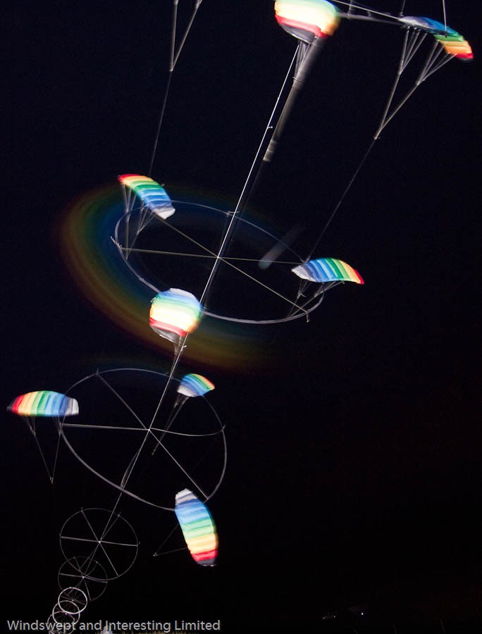
This is a network kite turbine. I call them "Daisy". It works as a multi-stage, tilted, hollow axis, tensile auto-gyro kite turbine. (If you're keen, this work is in conjunction with Oliver Tulloch's PhD at University of Strathclyde.) It uses a central axis lift line to guide and limit the travel of the rotary blades.
![]()
A recent long exposure pic of my Daisy kite turbine flying at night. Flash exposed the lines and kites, a torch exposed the rotor motion of the middle ring of kites.
Idea and Challenge
I've been asked to make a kite turbine, for local scouts to take with them, to an International Scouting Jamboree in Austria this year. The scouts have an eco camping challenge.
So I need to make this light as possible and safe to transport. Compatible with an e-bike will be a real bonus because even kids can work that regen tech. I want it to be capable of powering the bike itself and some camping gadgets. (Heavy juice ones like an electric kettle as well as USB toys.) We should be able to do this, the kite turbines have been outputting ~300W/kg flying material max so far.
I want to dual purpose as many bike parts as I can without killing bike functionality.
Having said that, I'm going use a small geared hub motor and wheel to convert rotary power to electrical power. Using a small geared hub motor for regen may be controversial among cycle purists as there will now be a cogging resistance if you cycle without using the motor. (why would you? E-bikes are amazing fun with the motor on). As explained here you have to weld or otherwise lock the freewheeling planetary gear for regen to work.
A couple whacky but possible extensions might be possible for this project. 1 Use the kite powered up from below for turbo fan propulsion (sounds fun) 2 Host the kite turbine in a tensile aerial network
Resource
I'm lucky to have a family who let me be a househusband / mad scientist. I'm no positive on the domestic balance sheet so I keep the budget minimal. This allows the projects to be fully replicable. I do spend on the motor controller for this project. (VESC6 has a very good open source hardware history and cheap derivative alternatives are available) I also spend quite a bit on carbon tubes. Cheaper fibreglass rods have worked on designs I've shared before.
Oliver Tulloch and I have a small budget for parts from ETP Scotland.
Plan
Whilst helping Ollie with his PhD, it has become apparent that, Daisy can be an efficient and clean way to to source energy at scale. Our much larger prototype had 30kg CO2 emissions equivalent in production, the complete prototype has a predicted carbon cost of energy of only 17g CO2/kWh in year 1 (already better than solar over its lifespan) and only 1.7g CO2/kWh with consideration of replacement components thereafter.
So we have been having fun making and testing both physical and mathematical models.
As for sticking to a rigid plan... Maybe. Reminds me, We're going to test more rigid rotor wings soon too.


")