J.B. Langston
-
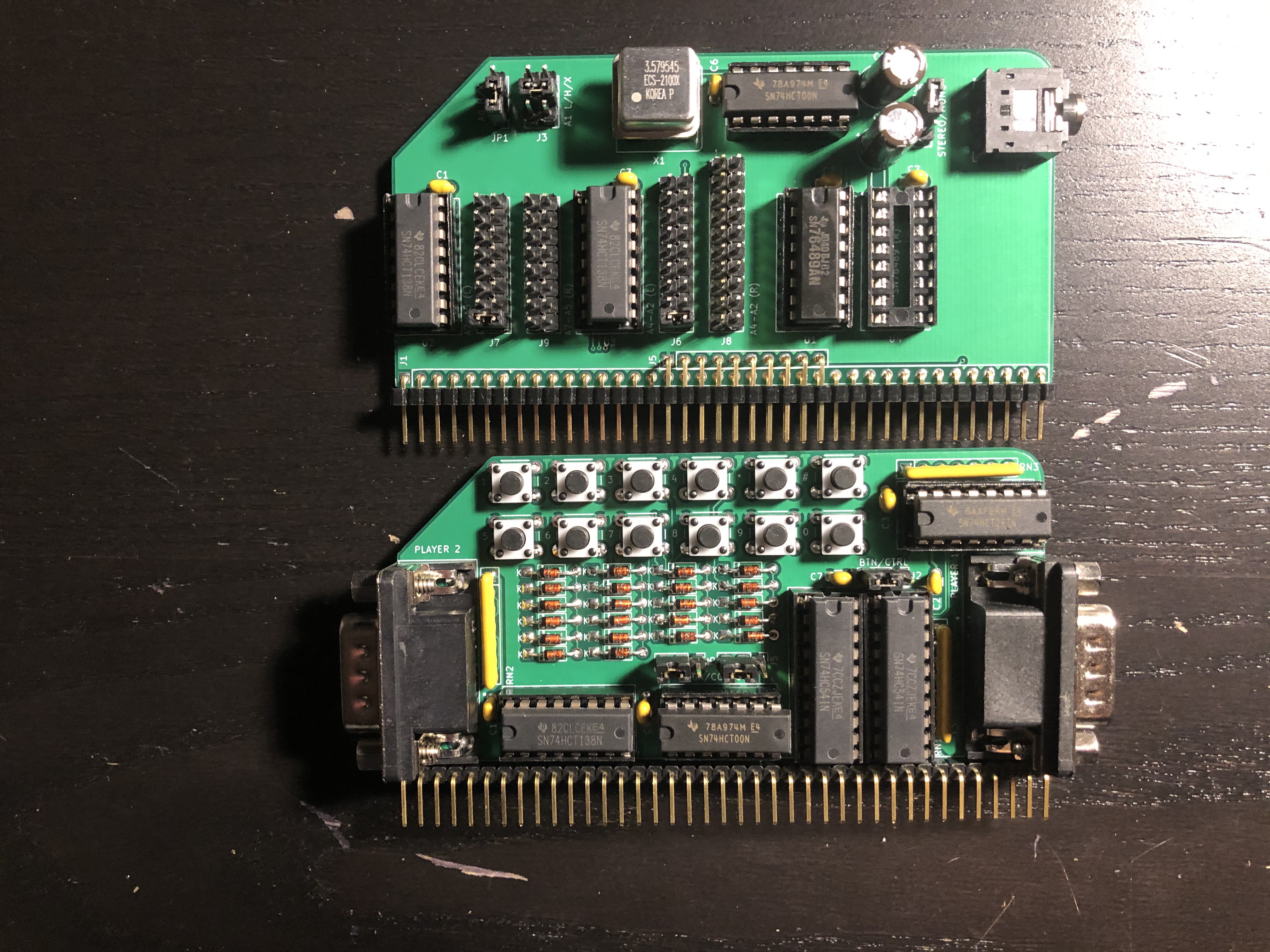
New Sound and Controller Board Revisions
10/04/2020 at 03:05 • 0 commentsRev 4 of the SN76489 sound board and Game Controller board are ready with a few tweaks to improve usability.
![]()
SN76489 Rev 4
Rev 4 adds a built-in 3.58MHz clock so that tones generated by the sound chip are independent of the bus speed. This improves compatibility with Z180-based systems where the clock speed would otherwise be too fast for the sound chip. In addition, to prevent random tones from playing before the sound chip is initialized, a flip flop blocks the clock from reaching the sound chip until the first write is made to initialize the chip. Asserting the reset line will reset the flip flop again and stop the clock. Additional jumpers are also added to fully decode A0 and A1 so a single address can be specified.
Game Controller Rev 4
Rev 4 allows the on-board numeric buttons to be used for both Player 1 and Player 2 where before they could only be used by Player 1. This change also prevents directional input from Player 2 from being erroneously interpreted as numeric input when using a non-Coleco controller. In addition, the button footprints have been changed to better fit standard tactile buttons.
-
Plasma Effect for TMS9918
09/07/2020 at 15:39 • 0 commentsPlascii Petsma by Cruzer/Camelot has one of the nicest looking plasma effects I've seen for the C64. Since he included the source code, I was able to port it to the Z80 and TMS9918.
On top of the features in the original C64 version, I have added the following interactive features:
- change the palette independent of the effect
- hold a particular effect on screen indefinitely
- switch immediately to a new effect
- runtime generation of random effects
- adjust parameters to customize an effect
In this article, I will explain how the code works. Before getting into the specific implementation details, it helps to understand how plasma effects work in general. Rather than write another explanation when others have already done it well, I'll refer you to this one, which covers the basic concepts using C code.
The implementation used here defines each plasma effect using a set of constant parameters:
SineAddsX:    defb    $fa,$05,$03,$fa,$07,$04,$fe,$fe
SineAddsY:    defb    $fe,$01,$fe,$02,$03,$ff,$02,$02
SineStartsY:  defb    $5e,$e8,$eb,$32,$69,$4f,$0a,$41
SineSpeeds:   defb    $fe,$fc
PlasmaFreqs:  defb    $06,$07
CycleSpeed:   defb    $ff
ColorPalette: defw    Pal01
Each of these parameters governs a specific aspect of the plasma calculation, which will be described in detail below. This scheme allows a huge variety of unique plasma effects to be specified in a compact format, and random effects can be easily produced by generating parameters in the appropriate ranges.
When implementing a plasma effect on an 8-bit computer, there are several challenges to overcome. First, the processor doesn't support floating point math or provide a sin function. This can be overcome using a sine table, which contains pre-computed sine values converted to 8-bit integers.
Normally, the amplitude of a sine wave ranges from -1 to 1. When converted to 8-bit integers, the amplitude ranges from -128 to 127. For ease of lookup, the sine table will contain 256 bytes representing a full period of the sine wave.
A single period of the sine wave first falls from 0 to -1, then rises back from -1 to 0, rises further from 0 to +1, then falls from 1 to 0. Each quarter of the period is the same curve, flipped vertically and/or horizontally. To save space, only the first quarter needs to be pre-computed and these values can be mirrored at runtime.
I used a python script to generate the first quarter of the sine table. The resulting data looks like this:
SineSrc:
        defb    $81,$84,$87,$8a,$8d,$90,$93,$96
        defb    $99,$9c,$9f,$a2,$a5,$a8,$ab,$ae
        defb    $b1,$b4,$b7,$ba,$bc,$bf,$c2,$c4
        defb    $c7,$ca,$cc,$cf,$d1,$d3,$d6,$d8
        defb    $da,$dc,$df,$e1,$e3,$e5,$e7,$e8
        defb    $ea,$ec,$ed,$ef,$f1,$f2,$f3,$f5
        defb    $f6,$f7,$f8,$f9,$fa,$fb,$fc,$fc
        defb    $fd,$fe,$fe,$ff,$ff,$ff,$ff,$ff
The MakeSineTable routine builds the sine table for a complete period from the precalculated quarter period. The first 64 values are copied verbatim from the precomputed values. The next 64 values are flipped horizontally by copying them in reverse order. The last 128 values are flipped vertically by complementing them. The vertically flipped values are written twice, first in forward order, and then in reverse order to flip them horizontally and complete the period. The resulting lookup table is stored on a 256-byte boundary so that a sine value can be looked up by loading a single register with the input value.
The next challenge to overcome is representing a smooth gradient of color when the video chip only has 15 colors to work with. To do this, I use dithering to combine different ratios of the 15 colors available. This is the full set of 64 gradient tiles used in Produkthandler Kom Her on the C64:
The TMS9918 tile mode defines 256 tile patterns, each of which is associated with a specific foreground and background color. For palettes of 8 colors each, I can use 32 tiles per color, so I only use every other tile from this set. The LoadPatternTable routine loads 8 copies of the 32 tiles into the TMS9918 pattern table.
The color table in Graphics I mode consists of 32 bytes. Each byte defines two colors for 8 consecutive patterns in the pattern table. The upper nybble defines the color of the 1 bits and the lower nybble defines the color of the 0 bits. For simplicity, palettes are stored with one color per byte, and the LoadColorTable routine combines each adjacent color into a single byte for the color table. Since I am using 8 colors and 32 tiles per color combination, I need to load each color combination into the color table 4 times.
With the pattern and color tables pre-loaded, I need only update the name table on each frame with the 768 bytes defining which tile will be shown in each of the 32x24 tile positions.
This brings us to the third challenge: calculating the values for the name table quickly enough to achieve a 60Hz frame rate. I use a couple of tricks to achieve this. First, the base image is pre-calculated only once for each effect and then distorted on each frame using simpler calculations.
The initial value for each tile is calculated in the CalcPlasmaStarts routine by summing together 8 sine waves of varying frequencies. Each of the 8 sine waves is defined by a starting value and coefficients for the x and y coordinates. The sine waves combine to create the complex contours of the image. The constants S, X, and Y in this formula stand for the SineStartsY, SineAddsX and SineAddsY parameters.
For each frame, the code applies a distortion effect to the original image. For each row y of frame n, the distortion value is calculated as follows. The constants S, P, and C, stand for the SineSpeeds, PlasmaFreqs, and CycleSpeed parameters.
For each row, the distortion value is calculated as described above, then for each column within the row, the distortion value is added to the starting value pre-calculated for that tile and saved into a back buffer for the screen.
In order to calculate each frame quickly, the loops are unrolled and all values are kept in registers. The CalcPlasmaFrame function sets up the registers for the unrolled loop that will follow. The registers are assigned as follows:
- de = pointer to first sine table entry
- hl = pointer to second sine table entry
- c = amount to increment first sine pointer between lines
- b = amount to increment second sine pointer between lines
- c' = current cycle count
- b' = offset to add to starting value for current row
- hl' = pointer to starting plasma values
- de' = pointer to screen back buffer
- a = temporary calculations
The MakeSpeedCode routine runs at the beginning of the program to copy the row and column sections of code into memory repeatedly to create the unrolled loops.
The main loop of the program repeatedly calls CalcPlasmaFrame for each frame, and then copies the back buffer into VRAM during Vsync.
A counter is used to determine when to switch to a new plasma effect. Each effect is displayed for 256 frames. Hold mode can be enabled to display the current effect indefinitely. Animation can also be disabled to display the initial image so that the effect of changing the parameters can be observed.
After the last frame, the main loop calls NextEffect to load the parameters for the next effect, then calculates the starting image and loads the color table with the specified palette.
A number of predefined effects are provided in the format described above, or the RandomParameters routine can generate parameters for a random effect if this mode is enabled.
Random numbers are generated using a combined LFSR/LCG pseudo-random number generator with 16-bit seeds. The random number generator is called repeatedly to generate each of the required parameters, which are then masked and adjusted as necessary to create the desired range of values.
At the beginning of the program, the RandomSeed routine seeds the PRNG from the screen buffer area of memory. This area of memory should contain relatively random data regardless of whether this program or some other program was loaded into that memory previously. To increase randomness, the offset into the screen buffer is determined by the refresh regsiter. On the Z80, this register automatically increments for each memory refresh cycle, and provides a source of relatively random 8-bit values.
Finally the ProcessCommand routine and associated functions provide a simple keyboard command interface to control the program.
Translating 6502 to Z80 as efficiently as possible was an interesting exercise. The lack of indexed indirect mode made it pretty tricky sometimes. I tried to play to the Z80's strengths when I could. I keep almost everything in registers and use the shadow register set extensively. The speed code is composed entirely of one byte instructions and the only things held in memory are the input and output arrays.
A lot of the complexity in Plascii Petsma's code was because he didn't want to use a custom character set. Since I didn't have this self-imposed restriction, I was able to remove that code and just calculate the tile names directly from the sine table, which simplified my code significantly.
The Plascii Petsma source code is well written and ingenious, but it's not well-commented or explained anywhere, so it took me a long time to understand it. Although good explanations exist for the general concept of plasma effects in high level languages, using assembly on an 8 bit platform adds another layer of complexity. Hopefully my explanation removes some of the mystery from how to implement plasmas on 8 bit machines.
-
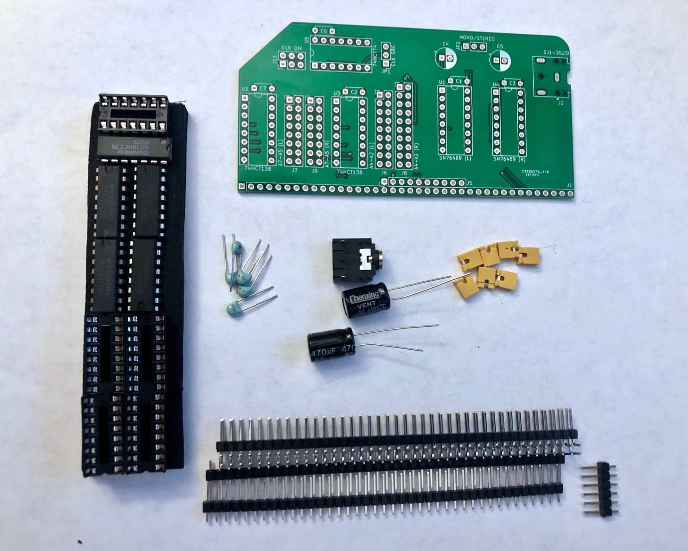
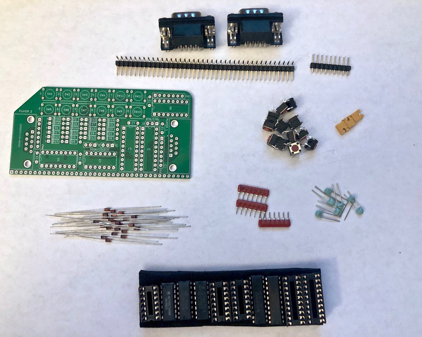
Sound and Controller Kits Now Available
01/09/2019 at 00:06 • 0 commentsSound Card and Game Controller kits are now available on Tindie.
![]()
![]()
These are in addition to the Video Card kits already available. Michael is planning to offer a newer version of the Video Card soon, but it only has two relatively minor updates: a diode on the interrupt line to convert it to open collector, and a jumper to allow using the TMS9918A's clock output as the RC2014 system clock. Both versions are fully compatible with the Sound and Controller boards and the games and other software discussed here.
Michael Kamprath is selling these kits with my permission, but I offer no warranty or guarantee of support.
-
Running ColecoVision Games
11/25/2018 at 17:07 • 4 commentsAfter you've added the sound, video, and controller interface cards to your RC2014, you will no doubt want to run games on it.
You will need to extract the ColecoVision BIOS (coleco.rom file) and game ROMs from your original console and cartridges, or, well, I'm sure you know how to use Google.
Once you have the ROMs, they need to be loaded into memory and launched. There are two ways to accomplish this: Using my z80ctrl monitor or from CP/M.
Loading via z80ctrl
To load the games via z80ctrl, put the ROMs on the SD card, and boot into the z80ctrl monitor.
When using the z80ctrl, the Pageable ROM module should be removed and the 64K RAM should be used by itself. Enter the following commands to load and run the game:
z80ctrl>loadbin 0 coleco.rom
z80ctrl>loadbin 8000 game.rom
z80ctrl>clkdiv 5
z80ctrl>run 0
These commands load the BIOS at address 0, the game at address 8000, set the clock divider to 5 (4 MHz), and start the Z80 at the BIOS entry point. At this point, if you have all your cards configured correctly, the game will start.
If you are using the 512K RAM/ROM board with z80ctrl, you must take a few extra steps:
z80ctrl>base 80000
z80ctrl>loadbin 0 coleco.rom
z80ctrl>loadbin 8000 game.rom
z80ctrl>poke 73b9 c7
z80ctrl>clkdiv 5
z80ctrl>run 0
The base 80000 command sets the base address to RAM so you that you can load the ColecoVision BIOS and game there. The poke command is a workaround to fix a problem that occurs when using the 512K RAM/ROM board. The next paragraph explains why the workaround is necessary and how it works. If you don't care, just skip it and remember that you need to do this.
When the Z80 is reset, the page register on the 512K RAM/ROM board gets cleared, so ROM gets paged in instead of RAM. The Z80 will read the first opcode from ROM before z80ctrl can switch back to the RAM. This is OK if the first byte in ROM and the first byte in RAM are the same, but in this case it isn't. If you have RomWBW flashed in your ROM, the first byte will be C3, which is a jump instruction. The first byte in RAM when the ColecoVision BIOS is loaded is 31, which sets the stack pointer. This is a problem because the C3 from ROM gets combined with the next two bytes in RAM, which form the address 73B9, so the first thing the Z80 does is jump to 73B9 and starts executing whatever random data is there. Poking C7 at 73B9 inserts a RST 00h instruction, which causes the Z80 to jump back to 0 and correctly execute the first instruction from the ColecoVision BIOS this time. If your ROM has something other than C3 in the first byte, then this workaround won't work.
A few games execute a halt instruction and wait for an interrupt. These games will cause the z80ctrl to stop the Z80's clock and return to the z80ctrl> prompt. If this happens, you will need to run the following commands to disable automatic halting and continue running the game:
z80ctrl>halt off
z80ctrl>run
Note that if you disable automatic halting, you will not be able to stop the game using the z80ctrl's halt button; you will need to use the z80ctrl's reset button instead.
Loading via CP/M
If you want to launch the games from CP/M, you will need the 512K ROM 512K RAM module for RomWBW instead. The Pageable ROM board that comes with the RC2014 Pro kit is not compatible because of a port conflict with the video card. When the game tries to write to the video card, this pages in the RC2014 ROM instead of the RAM containing the game, and the game crashes.
On the clock module, set Clock 1 to 3.6864 MHz. This is close enough to the ColecoVision's system clock of 3.57 MHz that games will work. Note that if you are using the standard SIO/2 module, reducing the clock speed will half your baud rate from 115200 to 57600. Make sure to adjust your terminal emulator accordingly.
In addition to a working installation of RomWBW, you will need the game loader I wrote. This is a small CP/M program that loads a game ROM into memory and then starts it.
The loader needs the ColecoVision BIOS in order to build, so you will need to obtain the coleco.rom file and place that in the same directory with loader.asm. Next you will need to cross-assemble the loader using sjasm. This should create a file called loader.out, which you will need to rename to coleco.com and upload to CP/M via Xmodem (which comes standard with RomWBW):
A>B:XM R COLECO.COM
Now initiate the upload from your terminal program (TeraTerm recommended). You will also need to upload ROM files for any games you want to play using the same procedure.
Once you have uploaded the loader and the games you want to play, launch a game using the following command:
A>COLECO GAME.ROM
This will take a few seconds to copy the game into memory and then print a message that the game has been loaded and the game will start. Once the game is started, you will need to reset your RC2014 to return to CP/M.
-
Full ColecoVision Compatiblity
11/21/2018 at 03:22 • 0 commentsThis project began several months ago with the development of my TMS9918A-based video card. With the recent addition of my SN76489 sound card and joystick interface, I have achieved full compatibility with unmodified ColecoVision games. Check out this video to see what it can do:
For those interested in all the gory details, I have produced a video with an in-depth explanation:
Additional details for each board, including a bill of materials and technical documentation, are on their respective Github pages:
A z80ctrl board or RomWBW is required to load games into memory and launch them.
Many thanks to JLCPCB for sponsoring the prototypes of these boards. Whether you want to manufacture my boards for your RC2014, or you need to prototype your own electronic project, JLCPCB is an excellent choice. They produce top quality PCBs for an incredibly low price and their service is fast. I routinely get 5 day or quicker turnaround on my projects, order placed to board in hand.
-
Video Card Kits Available
09/19/2018 at 13:42 • 0 comments![]()
Michael Kamprath has, with my permission, started selling ready-to-assemble kits on Tindie. Michael sent me one of the kits, which I put together, and it works great. I had no interest in selling these kits myself, but I was happy that Michael wanted to make it easier for people to get one of my boards if they want one. I offer no warranty or guarantee of support.
![]()
-
PCB Manufacturers Compared
08/14/2018 at 14:20 • 0 commentsNow that I have experience with three PCB manufacturers, I would like to share my impresson of each of them. The tl;dr is that having tried OSH Park, Seeed Studio, and JLCPCB, I will manufacture my boards with JLCPCB in the future.
Full disclosure: JLCPCB offered me a free batch of PCBs in exchange for writing a review; however, they did not influence this review, and what follows is my honest opinion based on my experiences.
Ordering Experience
OSH Park has a very user friendly website and allows uploading KiCad and Eagle PCB files directly so you don't have to convert them to gerbers first. They also make it easy to share your designs for other people to manufacture. This makes it much easier for a beginner to place an order.
Seeed Studio's website is considerably less friendly than OSH Park's. I had intended to order my second batch of boards from them but I encountered a problem with their online gerber viewer which made me nervous. The drill holes for all of the pads were not showing up in the correct place. I emailed Seeed Studio about this and they said it was a bug in their gerber viewer, and to go ahead and order my boards since someone would review the layout for any problems before manufacturing. However, the experience didn't inspire much confidence, and by the time they got back to me the next day, I had already placed my order with JLCPCB.
JLCPCB's website is also not as easy as OSH Park's, and requires generation of gerber files, but the ordering process went smoothly and the images from their gerber viewer looked correct. JLCPCB is also affiliated with EasyEDA, a web-based PCB design suite. I have played with EasyEDA some and it seems like a good tool, but all of my final designs have been done in KiCad. Strangely, I could not find any way to directly submit PCB designs from EasyEDA to JLCPCB for manufacture, which seems like a natural advantage they could offer. But unless I missed something, you still have to generate gerber files and upload them.
Price
OSH Park is much more expensive than manufacturers based in China. A batch of 3 boards cost $38.70 with free shipping. JLCPCB charged me $5 for a batch of 10 boards, and they had a special on my first order of 5 boards for $2. Even with $18.47 shipping from China factored in, it was more expensive to order 3 boards from OSH Park than was to order 15 boards with 2 separate designs from JLCPCB. Because of the expensive shipping, it makes sense to order multiple batches of boards from China at once if you can.
This isn't a completely fair price comparison, since the JLCPCB boards were made with a leaded HASL finish versus OSH Park's more expensive gold-plated ENIG finish. JLCPCB offers ENIG, which was still cheaper than OSH Park, but much closer in price. However, OSH Park only offers ENIG so you have to pay the premium for it even if you don't want to.
Seed Studio also offers HASL and ENIG options, and in general was slightly more expensive than JLCPCB for a comparable board. Since I didn't order from them, I don't have a record of the exact prices quoted.
Lead Time
Even though OSH Park is located in the US, my boards took longer to arrive than they did when I ordered them from JLPCB in China. With OSH Park, I placed my order on Feb 15, the boards shipped via USPS on Feb 26, and arrived on Mar 1 (total of 15 days). With JLCPCB, I placed my order on Jun 14, they shipped via DHL on Jun 19, and arrived on Jun 21 (total of 8 days). Since I never actually placed an order from Seeed Studio, I can't comment on their turnaround time.
Board Quality
JLCPCB and Seed Studio offer a choice between leaded HASL (the cheapest option), lead-free HASL, and gold-plated ENIG (the most expensive option). OSH Park only offers the more expensive ENIG option. I will refer you elsewhere for a discussion on the finer points of ENIG vs HASL. I have not ordered ENIG finish from JLCPCB or Seed Studio, so I can't offer an apples to apples comparison. What I can say is that I found the quality of the HASL finish to be just fine. The pads are solidly attached and they take solder easily. It is certainly more than good enough for making a few boards for a hobby project.
Although I have not ordered from Seeed Studio personally due to the problem I ran into with their gerber viewer, a friend had them manufacture some z80ctrl boards manufactured from my design and sent me several of these boards to evaluate. Overall I found the quality of the PCBs manufactured by Seeed Studio and JLCPCB to be very similiar.
Aside from the finish of the pads, one major difference I noticed between OSH Park and the other two manufacturers is the way they finished the edge of the PCB. OSH Park's boards have perforated tabs that connect the boards into a panel while they are manufactured. These tabs have to be broken off with pliers and this leaves rough spots around the edge of the board. If you have traces near the edge, you have to be careful not to damage them when breaking off the tabs. JLCPCB and Seeed Studio's boards have a much smoother finish around the edge of the boards with no tabs left on them.
I also had a manufacturing defect on my boards from OSH Park that did not occur on the boards manufactured from the exact same layout by Seeed Studio. The solder mask didn't completely cover the DTR trace near the edge of the board, causing a solder bridge that shorted between the trace and a neighboring GND pad. This prevented the AVR reset circuit from functioning correctly and could have damaged the DTR signal on my USB-to-Serial converter. I think this was partly my fault, since in my first revision of the z80ctrl board, I ran the trace from the DTR signal very close to the edge of the board. In later revisions of the board, I rerouted the trace so it is further away from the edge of the board, but it is a point in Seeed Studio's favor that even with the trace near the edge of the board, their boards did not have this problem.
Conclusion
I really like OSH Park's ordering experience, but Seeed Studio and JLCPCB definitely win on price and turnaround time. Also, in some ways, I feel that they produce higher-quality boards than OSH Park. Seeed Studio needs to work out the bugs on their gerber viewer so that people can trust it when ordering their boards. JLCPCB's website is not as easy to use as OSH Park but it works well, and provides plenty of documentation to help you figure out how to generate gerber files from the various CAD packages. All in all, I think all three manufacturers are a decent choice for hobbyist PCB makers, but after trying all three, I plan to continue manufacturing my boards with JLCPCB in the future.
-
Zero Vias
07/27/2018 at 01:42 • 0 comments![]()
I admit that this served no purpose beyond the indulgence of my OCD, but I'm still damn proud of this achievement.
-
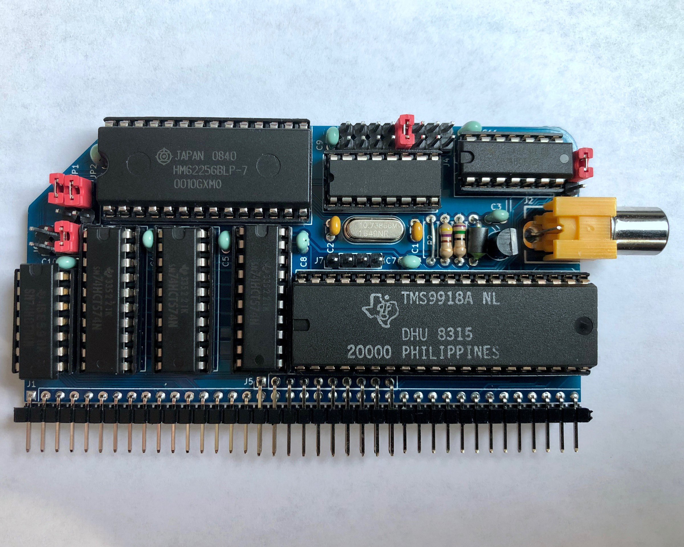
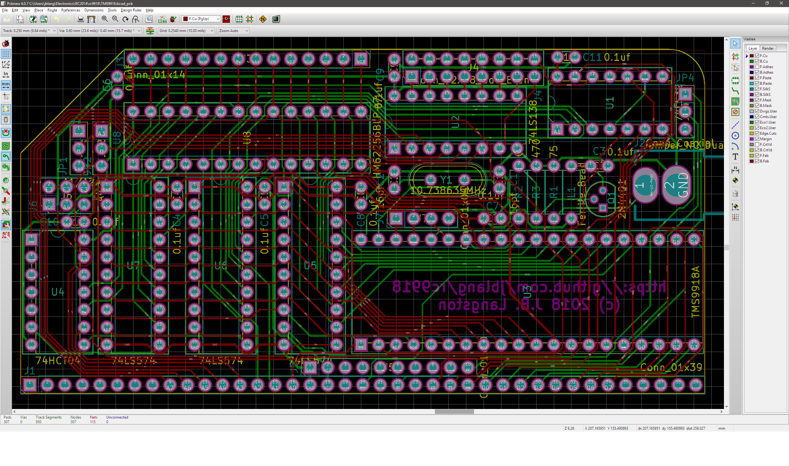
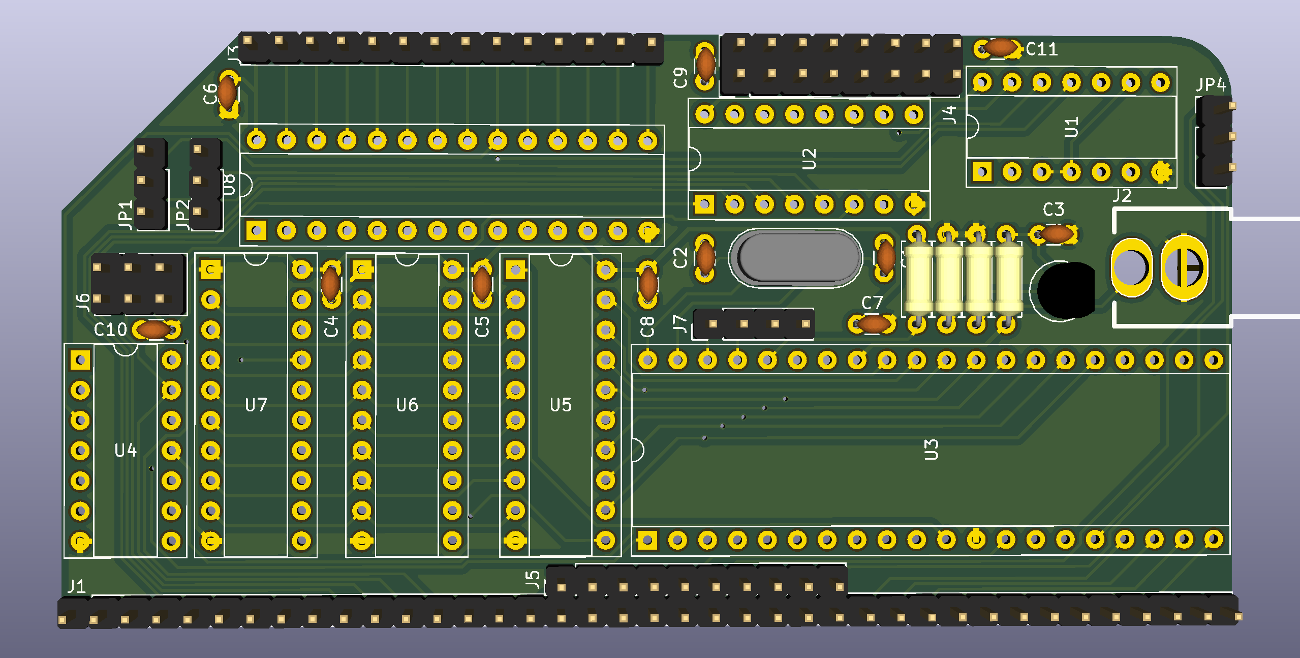
New Board Revision
07/24/2018 at 01:36 • 0 commentsI've been working on a new revision of my board that will work with unmodified ColecoVision games. I had some success getting a few games to run by modifying the ColecoVision BIOS but many games bypass the BIOS and access the ports directly, so it would be a lot of work to modify them all for compatibility.
![]()
The new revision will have basically the same BOM as before with the addition of more jumpers. Based on feedback from Mark on the RC2014 mailing list, I have hopefully made it compatible with the Sord M5 computer as well.
Here's how the address decoding works:
- J4 configures address bits 7-5 which lets you select a block of 32 addresses: 00-1F (left) ... E0-FF (right). For ColecoVision, you would set this to A0-BF (6th position). For MSX, you'd set it to 80-9F (5th position). For Sord M5, you'd set it to 00-1F (1st position).
- J6 configures address bit 4. There are 3 options: ignore (left), 0 (middle), or 1 (right). This lets you use the entire 32 address range, the upper half, or the lower half, respsectively. For ColecoVision, you would set this to ignore (left). For MSX and Sord, you would set it to 1 (right).
- JP1 configures address bits 2 and 1. In the upper position, they must both be 0. In the lower position, they are ignored. For MSX, you would set this to the upper position. For ColecoVision and Sord, you would set it to the lower position.
- JP2 configures address bit 3. In the upper position, it must be 1. In the lower position, it is ignored. For MSX, you would set this to the upper position. For ColecoVision or Sord, you would set it to the lower position. This allows configuration of the correct ranges for all 3 systems:
- MSX 1 (98 and 99)
- ColecoVision (A0-BF, with BE and BF typically used)
- Sord M5 (10-1F; with 10 and 11 typically used)
For other Z80/TMS9918A systems, such as the SpectraVideo and MTX, it should at least be possible to configure a superset of the correct addresses, but it may not be possible to decode the addresses as precisely as the original system. Depending on what other peripherals such a system has mapped to any partially decoded addresses, this may or may not cause a conflict. This is the best that I can do without adding any more decoding chips, which I don't have room for on the board.
I also added a jumper (JP4) to output the TMS9918A's interrupt signal to either INT (upper position) or NMI (lower position) on the RC2014 bus. There is now a second row of bus pins to connect NMI to the RC2014 bus. ColecoVision connects the video interrupt to NMI, so this change was necessary for compatibility. MSX uses INT, and most other systems do as well.
Finally, I added a header (J7) with pins for (left to right) CPUCLK, GROMCLK, EXTVDP, and GND. This should allow the CPUCLK and GROMCLK signals to be used via jumper cables with other boards the need them, for example on the Sord M5. It should also be possible to daisy-chain multiple TMS9918A chips using the EXTVDP signal, or to genlock an external video source. I added a GND pin to use with an external video source if needed.
I am going to check these changes into Github now but I am waiting to design my SN76489A sound card and ColecoVision joystick interface boards before I have them manufactured.
-
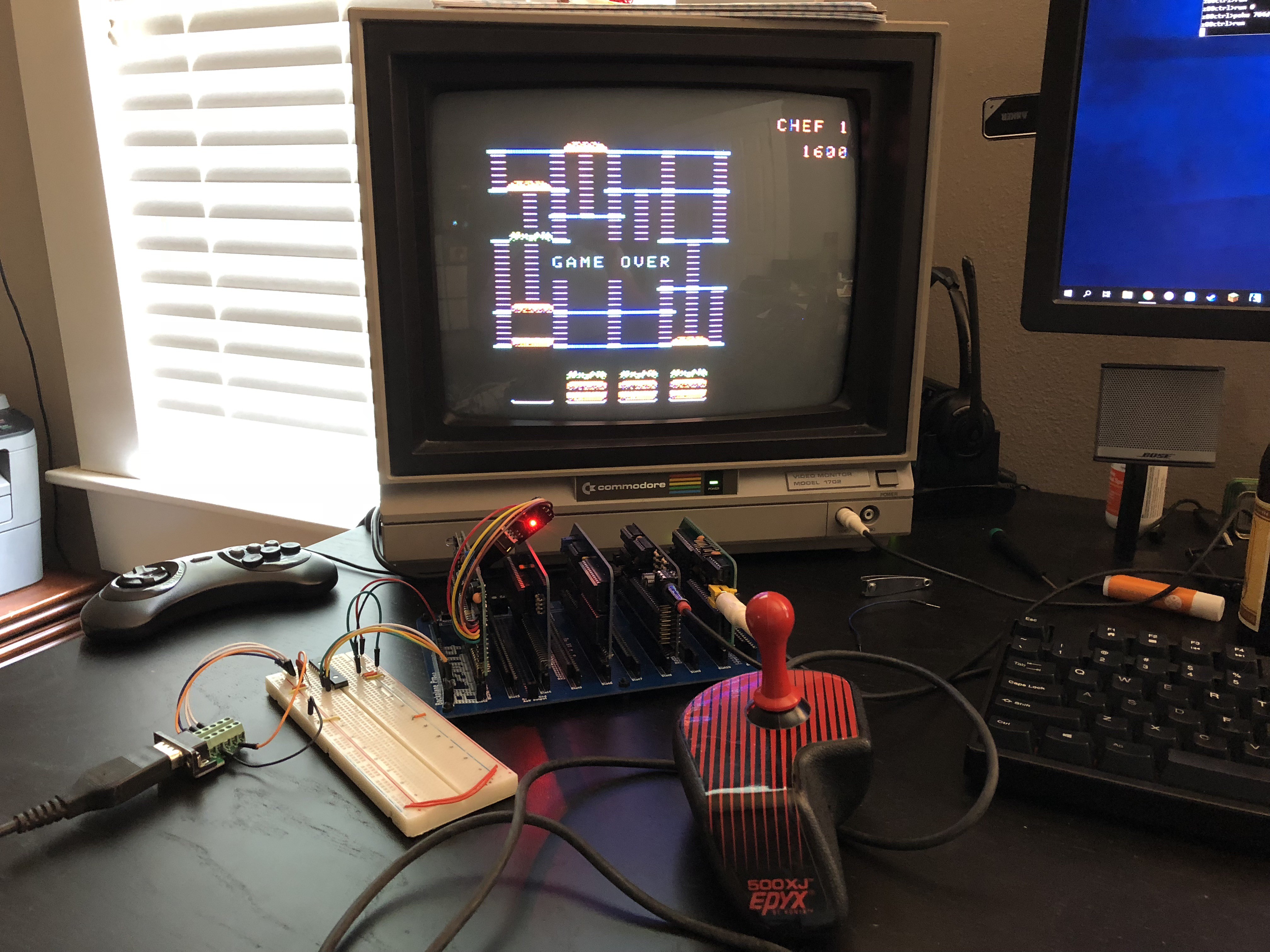
ColecoVision Games
07/08/2018 at 18:33 • 0 commentsI have successfully run a few ColecoVision games with only a small modification to the Coleco BIOS in order to change the port used for the TMS9918A and make the maskable interrupt handler redirect to the NMI handler because the ColecoVision uses NMI for the TMS9918A's vblank interrupt, whereas my board uses INT.
![]()
So far, Donkey Kong and Burger Time are fully playable. For some reason I haven't figured out yet, Donkey Kong Jr hangs after the skill select screen.
I'm using a second MCP23S17 I/O expander hooked up to the SPI bus on my z80ctrl board to read the joystick. The z80ctrl reads the joystick value via SPI, and relays the results back to the Z80 over port 0xFC, where the ColecoVision code expects to find them.
Unfortunately some newer games talked directly to the hardware ports instead of going through the BIOS so I will have to individually patch those games. I have gotten as far as the title screen in Centipede and Star Wars after patching their ROMs to use the correct video ports.
None of the games have any sound currently because the ColecoVision uses a TI SN76489 instead of the YM2149 chip that I have in my RC2014. I may design a SN76489 board for the RC2014, or it might be possible to patch the ROMs to use the YM2149 instead, since both chips had similar capabilities. I haven't researched what all would be involved in doing this yet.
Inexplicably, I am terrible at all of the games I've played so far. Clearly there is some kind of subtle incompatibility that is making these old games much harder than I remember them. Yeah, that's gotta be what it is.