Close
0%
0%

Stomach Acid Powered Smart Pill

Zn-Cu stomach acid based bio-galvanic cell powers a hacked activity tracker small enough to swallow and reconfigured as a 'smart pill'.

Similar projects worth following
Heard of using lemons, potatoes or salt water to create a simple battery? Stomach acid (dilute hydrochloric acid) can be used in the exact same way and is significantly more powerful. I use an array of zinc (anode) and copper strips (cathode) immersed in stomach acid (electrolyte) to turn my stomach into a galvanic cell battery. The stomach battery powers a hacked activity tracker small enough to swallow and reconfigured as a body monitoring 'smart pill'. The user's stomach is the smart pill's battery. By incorporating a $25 hacked activity tracker into existing research I am trying to make stomach acid powered smart pills inexpensive and open source.

Smart pills are already being used by doctors to save lives. Many more are being developed. There is an endoscope camera smart pill, a  colon cancer detecting smart pill, an ulcerative colitis monitoring smart pill, a medication compliance smart pill, a targeted medication delivery smart pill, a microbiome monitoring smart pill, a battery removing origami robot smart pill, and quite a few more. Powering smart pills is difficult. High density batteries, especially lithium batteries, tend to be fairly toxic and only very small batteries will fit in a pill. It would be convenient if we could power devices by turning our GI tract into a battery. The common Alkaline battery uses sulfuric acid, along with zinc and manganese, to generate electricity. The concentration of hydrochloric acid (HCl) in stomach acid (gastric fluid) is about 0.16M and can be used to create a battery the same way sulfuric acid is used in alkaline batteries. The smart pill I'm building is about developing a technology that will make other smart pills more effective. My goal is to monitor the voltage and maximum current produced after it is swallowed and send data to an app over Bluetooth. As the project progresses, I have also started testing Magnesium-Copper galvanic cells.

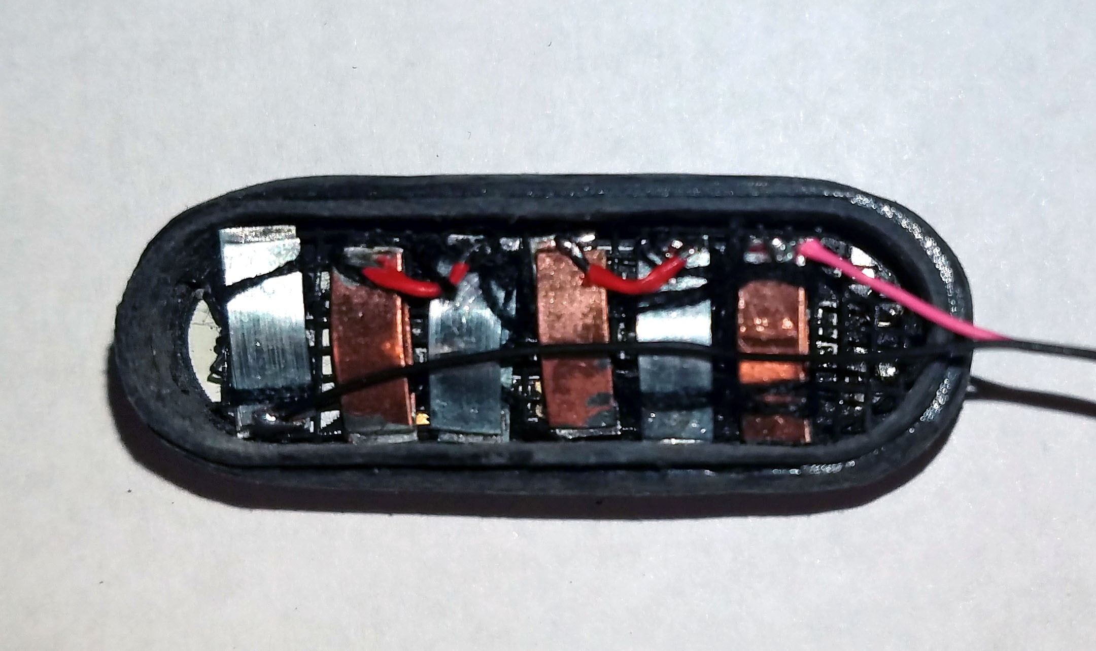
(Above) Magnesium-copper (Mg-Cu) galvanic cell encased in the smart pill enclosure immersed in a 0.16M hydrochloric acid (HCL) solution. The voltage across the cell when fully immersed is 1.29V (average over one minute).
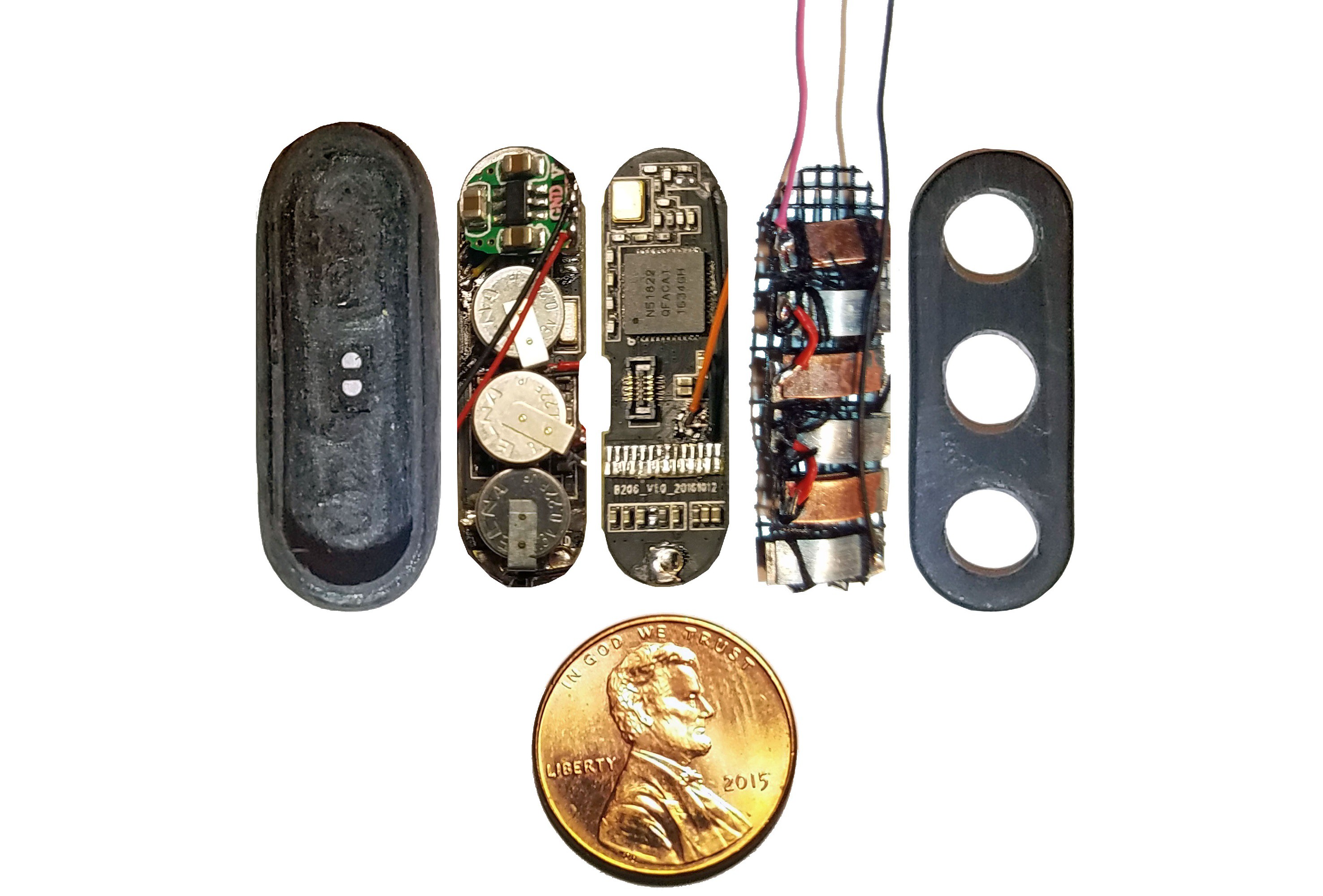
(Above) Components of smart pill sandwiched into injection molded plastic enclosure arrayed in ascending order left to right.

Far left: shaped and ground out activity tracker enclosure.

1st from left: three super capacitors in parallel, back charge protection diode, voltage boost converter, bottom view of activity tracker PCB.

2nd from left: top view of activity tracker PCB including Nordic nRF51822 ARM Cortex-M0 SoC chip.

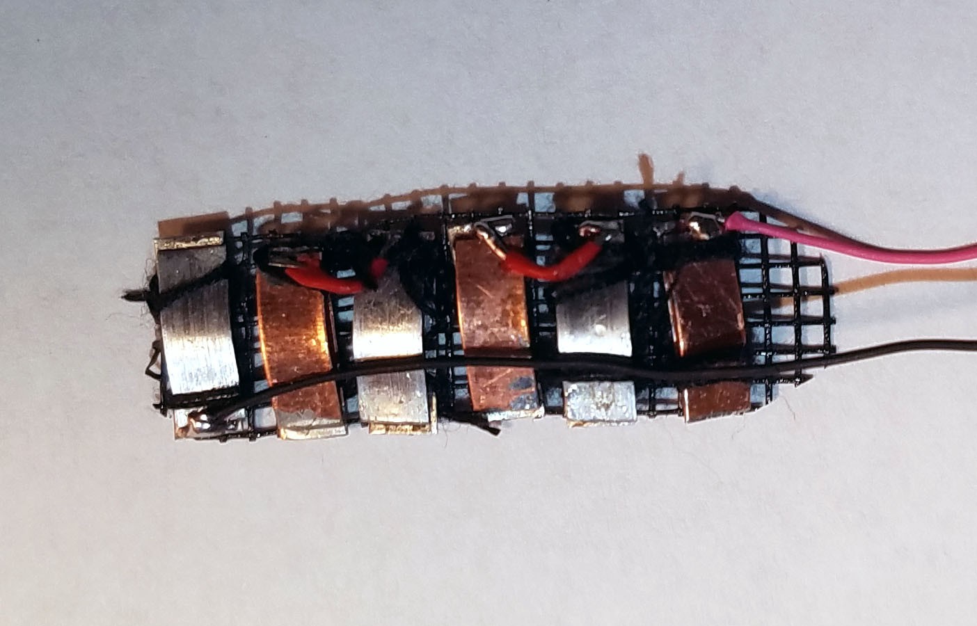
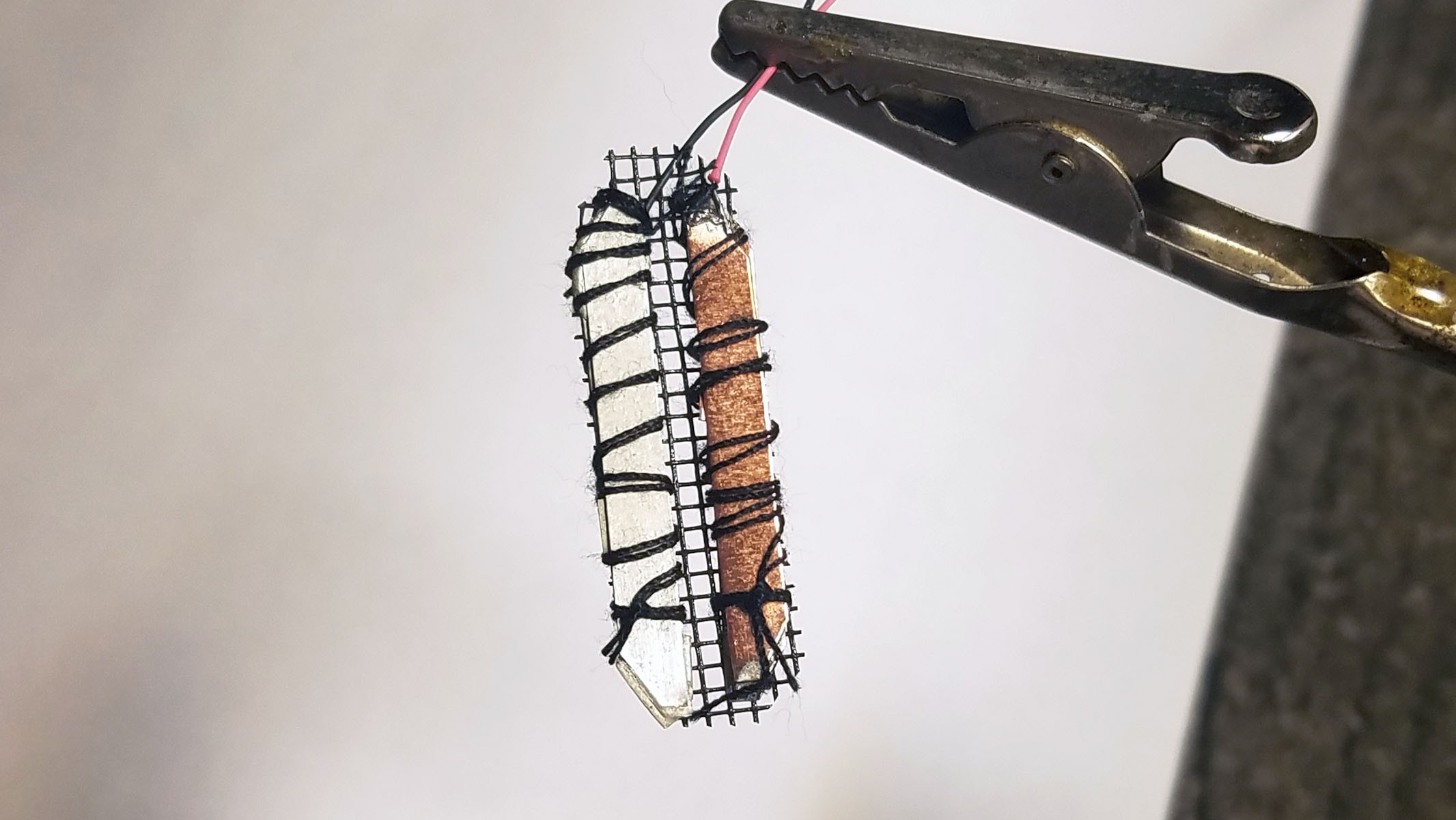
3rd from left: pile of three Zn-Cu Galvanic cells in series. The electrodes have been sewn down to a plastic mesh to keep them in place and allow free flow of electrolyte. 

Far right: enclosure cap with holes for gastric fluid containing hydrochloric acid electrolyte to enter device. The enclosure will be filled with epoxy until everything but the galvanic cells are encased so gastric fluid entering the enclosure will not damage the electronics.

DESIGN
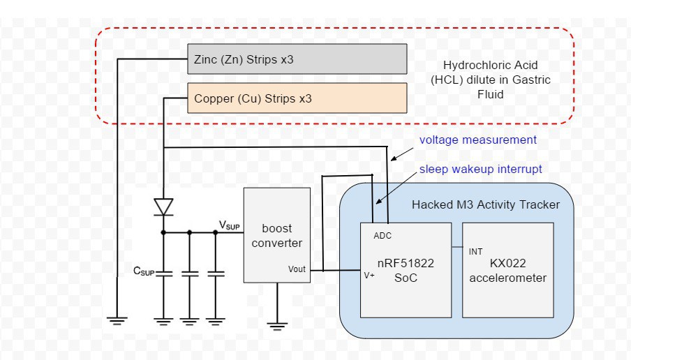
Build Steps 

  1. The OLED display, battery and vibration motor of a small hackable activity tracker are removed and the enclosure is shaped with a Dremel to make it more pill-shaped and create extra space.
  2. Three pairs of Zn-Cu strips as long as the activity tracker circuit board is wide are created. These Zn-Cu strip pairs are layed in an alternating array - the array is as wide as the activity tracker is long. The Zn-Cu pairs are wired so that they form three galvanic cells in series. I sew all these strips down to a of plastic mesh the same size as the activity tracker PCB to keep them in place. *Note: currently undecided as to whether Mg-Cu or Zn-Cu is best. Going back and forth for now.
  3. The positive (copper) lead from the galvanic cell bank is connected to a Schottky diode and the negative (Magnesium) lead is connected to ground on the activity tracker PCB. 
  4. Three tiny coin type 3.3v super capacitors are wired in parallel so that they form a capacitor bank. The positive leads from the capacitors are connected to the diode. The diode will prevent any back charge from the capacitors to the Zn-Cu strip galvanic cell which could cause...
Read more »

panasonic_abc0000ce19-1196936.pdf

super cap datasheet

Adobe Portable Document Format - 53.56 kB - 09/22/2018 at 12:56

Preview

Ingestible, Controllable, and Degradable Origami Robot.pdf

This is a smart pill robot designed to help people who have swallowed a Lithium coin battery. I would never do such a thing, but if I did, this awesome pill robot could help me. Maybe.

Adobe Portable Document Format - 2.01 MB - 06/17/2018 at 14:53

Preview

Prolonged-Energy-Harvesting-For-Ingestible-Devices_Nadeau2017_Nature_Biomedical_Engineering.pdf

This is the paper in Nature Biomedical Engineering for the MIT project my own project is largely based on.

Adobe Portable Document Format - 1.59 MB - 06/17/2018 at 09:22

Preview

  • 1 × M3 Activity Tracker An extremely small Nordic nRF51822 SoC based activity tracker.
  • 3 × Pure Copper (Cu) Ribbon/Strips 3mm wide, 0.25mm thick, 10.1mm long
  • 3 × Pure Magnesium (Mg) Ribbon/Strips 3mm wide, 0.25mm thick, 10.1mm long
  • 3 × Pure Zinc (Zn) Ribbon/Strips 3mm wide, 0.25mm thick, 10.1mm long
  • 1 × two part 5 minute epoxy for filling up the hacked activity tracker enclosure and securing anything else that might come loose or cause problems in the stomach

View all 10 components

  • Testing Mg-Cu and Zn-Cu Galvanic Cells

    Curt White07/17/2018 at 00:57 0 comments

    I'm testing Magnesium-Copper (Mg-Cu) and Zinc-Copper (Zn-Cu) galvanic cells in a 0.16M solution of Hydrochloric acid (HCL). This solution of HCL approximately matches the PH and HCL concentration in the human stomach (though conditions in the stomach can vary). The Mg-Cu cell initially produces a voltage (electric potential) of 1.46V, however, the surfaces of the Mg strips rapidly corrode and the voltage plateaus at 1.28V after one minute. 

    The Zn-Cu test is a little more complex. I had already tested the Zn-Cu cell before I started shooting this video. The residual HCL in the thread and plastic mesh surrounding the Zn and Cu is functioning as an electrolyte. This is why there is a significant electric potential before the cell is even submerged in HCL. When the cell is submerged, the electric potential drops to about 0.5V. Why? This particular Zn-Cu cell is actually three Zn-Cu cells in series. I have separated the cells with plastic flaps which are supposed to act as ion barriers (essentially they insulate the cells from one another). The plastic flaps function well enough when the cell has residual HCL on it, but when the cells are submerged they short across one another.

    Electric potential of Zn-Cu cell bank at various functional levels:

    1.45V: Ion barriers working, three Zn-Cu cells in series.

    0.76V: Center cells shorted, combined cells acting as a single cell.

    0.5V: Significant short across all cells.

  • Designing a Galvanic Cell - Plain Language Electrochemistry

    Curt White07/16/2018 at 00:47 3 comments

    From a practical perspective, designing a galvanic cell (or bank of cells) is extremely easy. They can be treated like batteries because they are like batteries. For the purpose of this log (and project in general) I am going to describe everything in plain language instead of scientific terminology. If you want to deep dive into electrochemistry Google is your friend. 

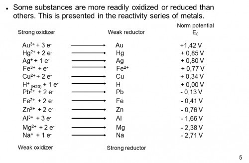
    1) Pick anodes and cathodes that maximize difference in reactivity. The metals (or the like) you choose will determine the voltage produced by your cell. To determine what voltage your anode and cathode will produce, consult a reactivity table like below:

    You want to pair a reactive metal (negative electric potential in the chart) with an unreactive metal (positive electric potential in the chart). The maximum voltage produced by your galvanic cell will the sum of reactivity.

    For a copper-zinc cell the ideal voltage will be 0.34V(Cu) + 0.76V(Zn) = 1V

    Lithium is the most reactive metal easily incorporated into a battery, which is why it produces such high power density batteries.

    2) Pick a highly acidic electrolyte. The actual voltage produced by a galvanic cell will never equal its ideal voltage. How close you get depends largely on how good your electrolyte is. The role of the electrolyte is to transport ions. In general, strong acids are the best electrolytes because, in general, they can pack the most ions.

    3) Maximize the surface area (and probably mass) of your annode and cathode to maximize available current. Although the voltage of your cell is determined by the reactivity of the annode and cathode, the current supplied by the cell is determined by the surface area of the annode and cathode exposed to the electrolyte. You want an electrolyte that can transport as many ions as possible, but this is still limited by the availability of ions (annode/Zn) and places to put ions (cathode/Cu). More ions means more current.

    4) Although voltage of a single cell is limited by annode/cathode reactivity, voltage can be increased by placing cells in parallel - just like batteries. However, cells have to be isolated otherwise you will get a short between cells. To put it more specifically, an ion barrier between cells is necessary if they are adjescent in an electrolyte. 

    Pretty cool stuff.

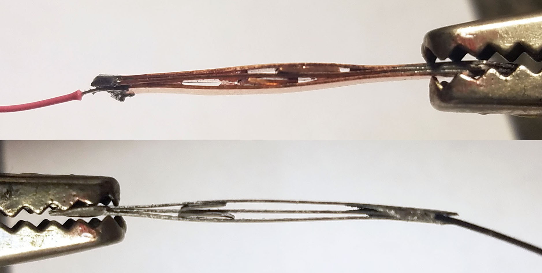
    In all the cells I've built I have sandwiched multiple strips of metal for each anode and cathode (in the above picture you can see how I've sandwiched Magnesium and Copper) in an attempt to maximize surface area, and therefore maximize available current.

  • Data Logging Android/iOS App that Leverages Connectionless BLE GAP Advertisements to Minimize Power Consumption

    Curt White06/26/2018 at 16:53 0 comments

    UPDATE! Try out the app for yourself if you have android: https://github.com/curtpw/biogalvanic-smartpill/blob/master/app/smartpill-android-app-debug.apk

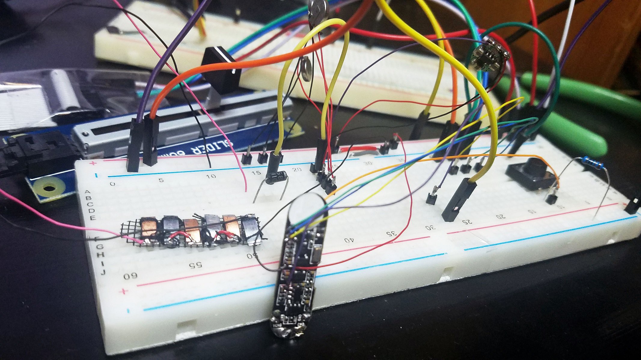
    Now that the smartpill is wired up on a breadboard, it’s time create an app so we can log data wirelessly (and eventually through the abdomen). The big question is how to do this using Bluetooth BLE, a widely available standard that is not geared towards intermittent split second connectivity. Just connecting (“pairing”) over BLE can take seconds, while we want to turn the smartpill’s radio on for a fraction of a second. Luckily there is a way to transmit data over BLE without a connection: GAP advertisement information. Every BLE device constantly transmits basic information about itself – this is what you see when you scan for available Bluetooth devices. Only part of this information (“UUID”) is necessary, the spelled out name (“macbookabc”, “fitbit123”, “smartpillxyz” etc.) is for user convenience. Instead of using this extra ‘name’ information to advertise the smartpill for potential pairing, I use it to transmit data. Every time the smartpill turns on for a fraction of a second, it changes it’s BLE ‘name’ to the latest sensor values (for now voltage sensing ADC). My app is constantly scanning for new BLE devices (GAP advertisement information). The smartpill doesn’t have to wait for a connection to be created, the app grabs the sensor values from the advertised ‘name’ information the moment the smartpill is detected by the app. This dramatically decreases the length of time the smartpill’s Bluetooth radio has to be turned on which is crucial to minimizing power consumption.

    I have used the Cordova based Evothings platform to create a hybrid Android/iOS app using web dev style Javascript. Evothings is, bar none, the easiest way to create apps for BLE devices. Anyone who knows a little JS/HTML/CS can pick it up quickly. Evothings sits on top of the venerable Cordova hybrid app creation framework. I have placed the Evothings project folder for this data logging app in the smartpill GitHub repository.

  • Hacking the M3 Nordic nRF51822 Based Activity Tracker

    Curt White06/17/2018 at 15:00 0 comments

    FOR FULL DETAILS ON HACKING THE M3 ACTIVITY TRACKER AS WELL AS PURCHASE LINKS SEE MY Hacking a $25 nRF51 ARM Cortex Activity Tracker PROJECT

    M3 Specs:

    • Display: 0.69" 16*64 OLED
    • MCU/SoC: nRF51822 258kB Flash Memory 32kB RAM
    • Accelerometer: Kionix KX022-1020 using SPI interface
    • Heart Monitor: PixArt PAH8001 green LED PPG
    • Battery: 40 mAh lithium polymer
    • Waterproof: IP67
    • Device size: 18.0*11.2mm

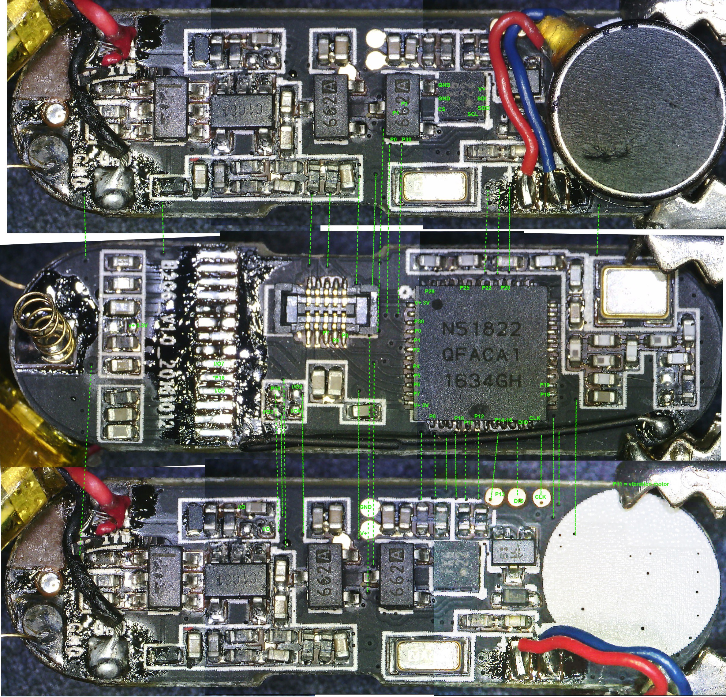
    This is a high resolution microscope image of both sides of the main board aligned so that pins and traces can easily be mapped. I currently use this for reference purposes when using the hacked M3 as a development platform.

    Purchase Links

View all 4 project logs

  • 1
    Constructing the Zinc-Copper Galvanic Cells

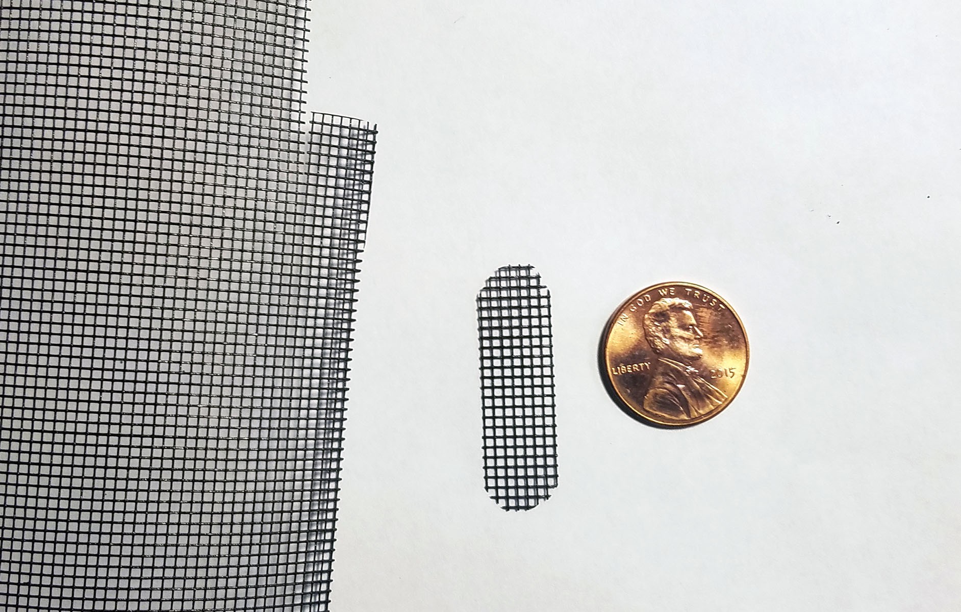
    The activity tracker PCB is used to trace and cut out a piece of plastic mesh so that it will fit flush in the activity tracker enclosure.

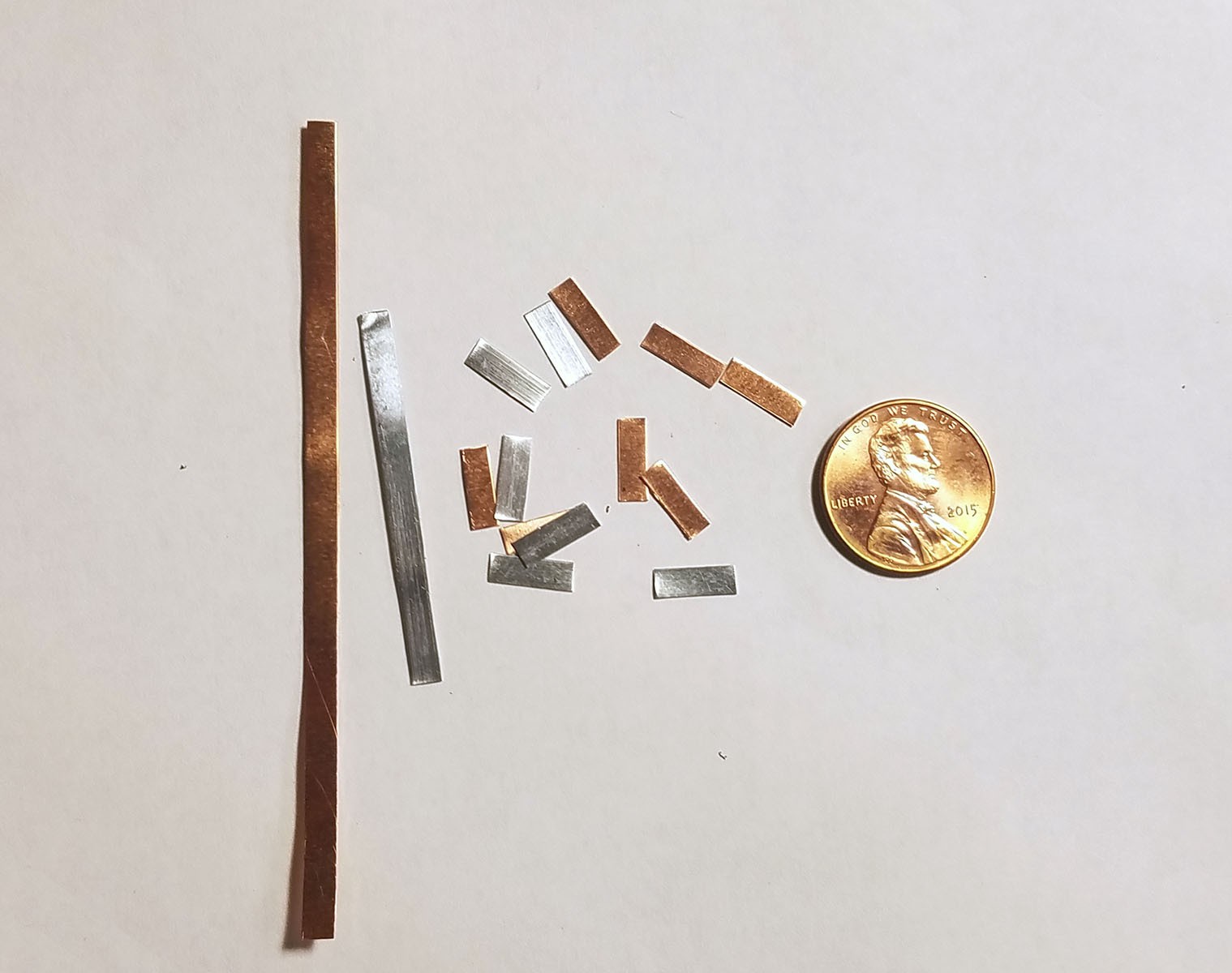
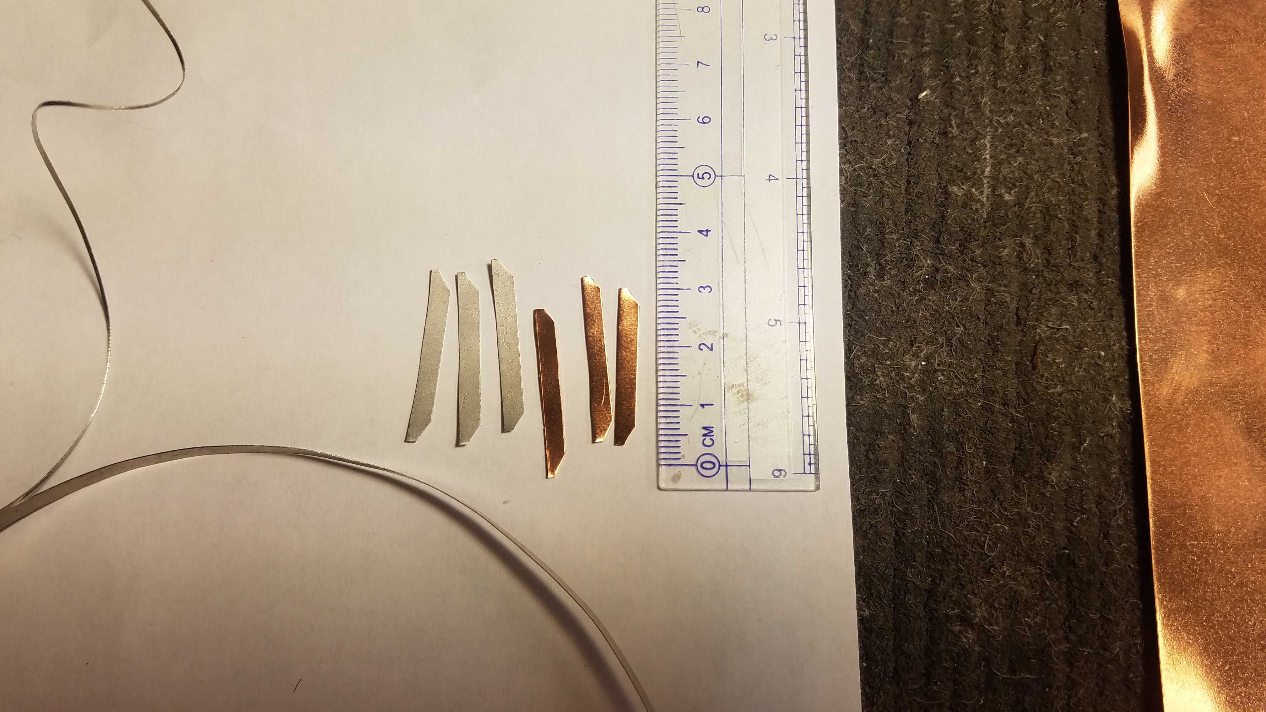
    6 strips of copper and 6 strips of zinc are cut 3mm wide and 9mm long (the width of the activity tracker PCB). The copper and zinc are about 0.25mm thick (I purchase 30 gauge sheets).

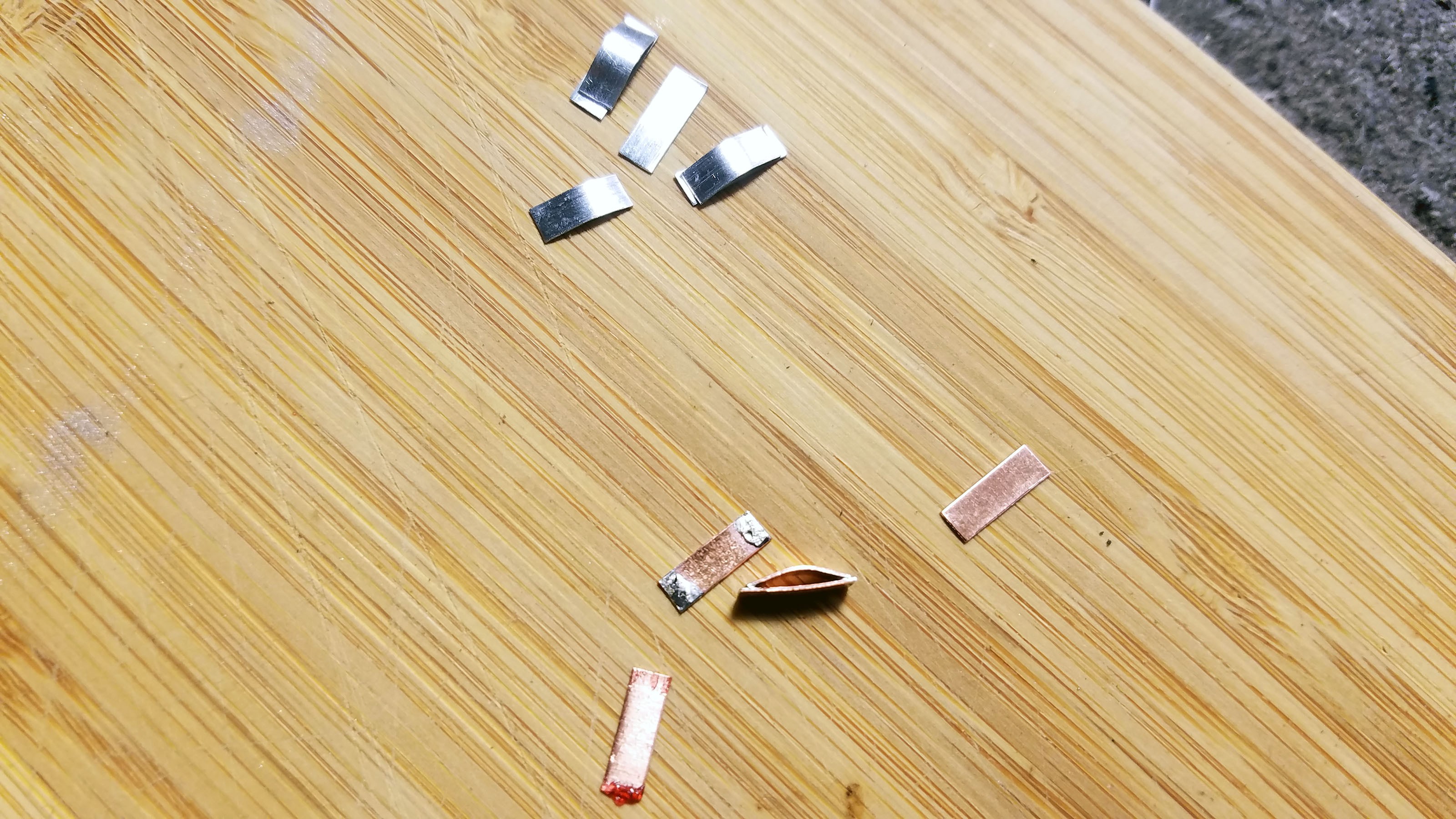
    Half of the strips are bent and then soldered to the other half (Cu to Cu etc.) so that the bottom strip is flat and the top strip forms an arch with about 1mm of clearance underneath. These two strip 'sandwiches' will have more mass and greater surface area which will increase the current produced by the galvanic cells. 

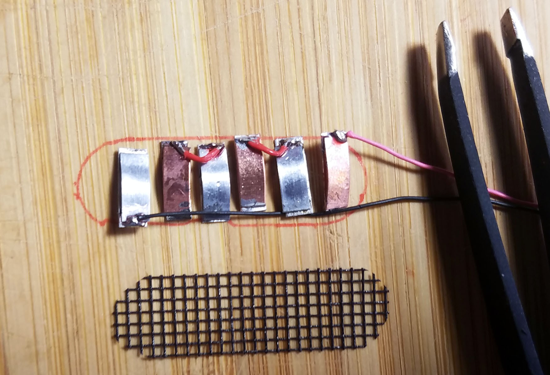
    The soldered strip pairs are arranged in alternating order according to metal type. The ground lead for the cells is soldered to the end zinc strip and the positive lead is soldered to the end copper strip. Each of the remaining copper strips is soldered to one of the remaining zinc strip to complete a series of three galvanic cell pairs.

    The metal strips are sewn down to the plastic mesh so that they are evenly spaced apart when the entirety is placed inside the activity tracker plastic enclosure.

    The completed array of galvanic cells is placed inside the enclosure to make sure everything fits and stays in place.
    POST TESTING ADDITIONAL STEPS

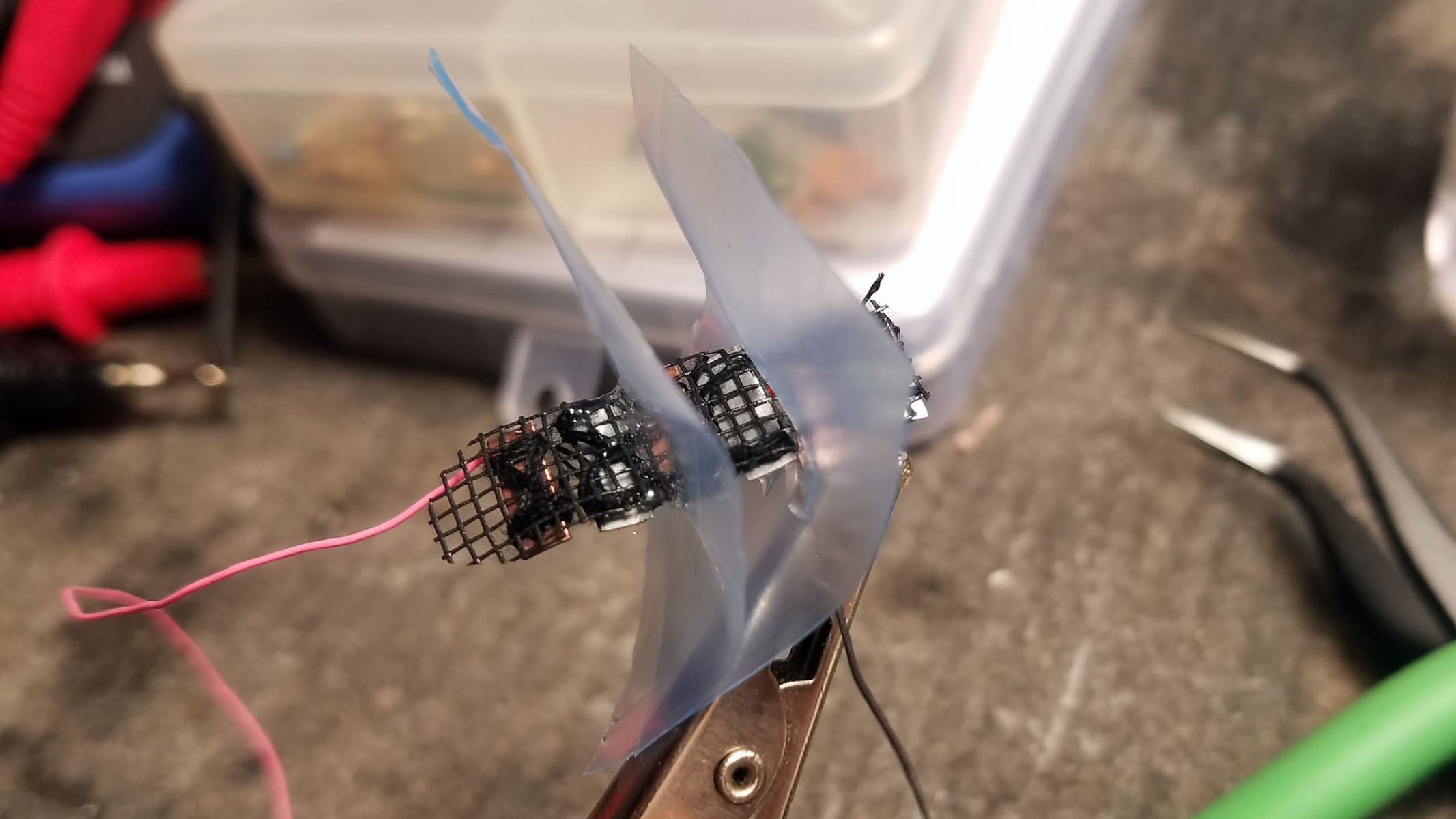
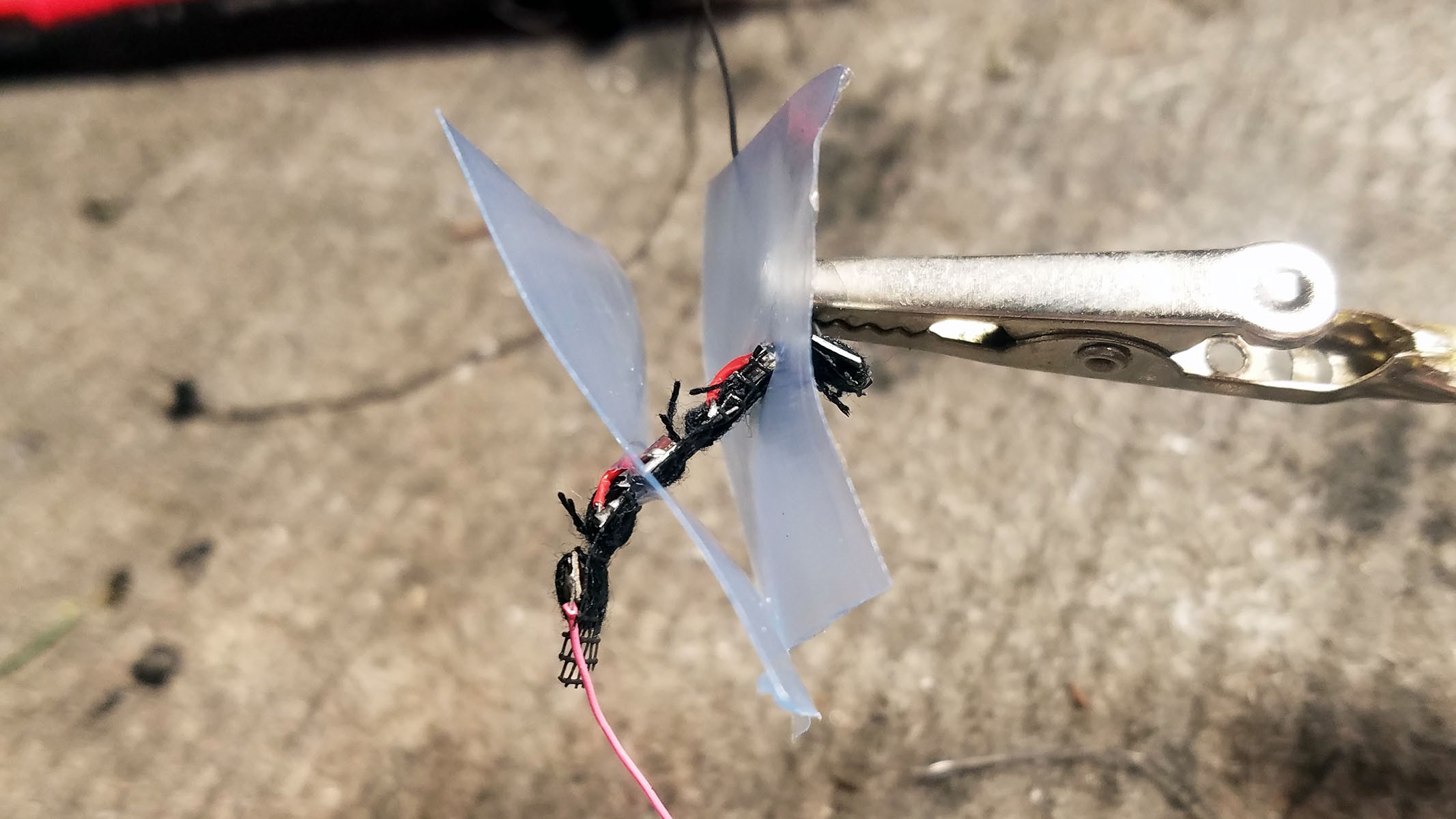
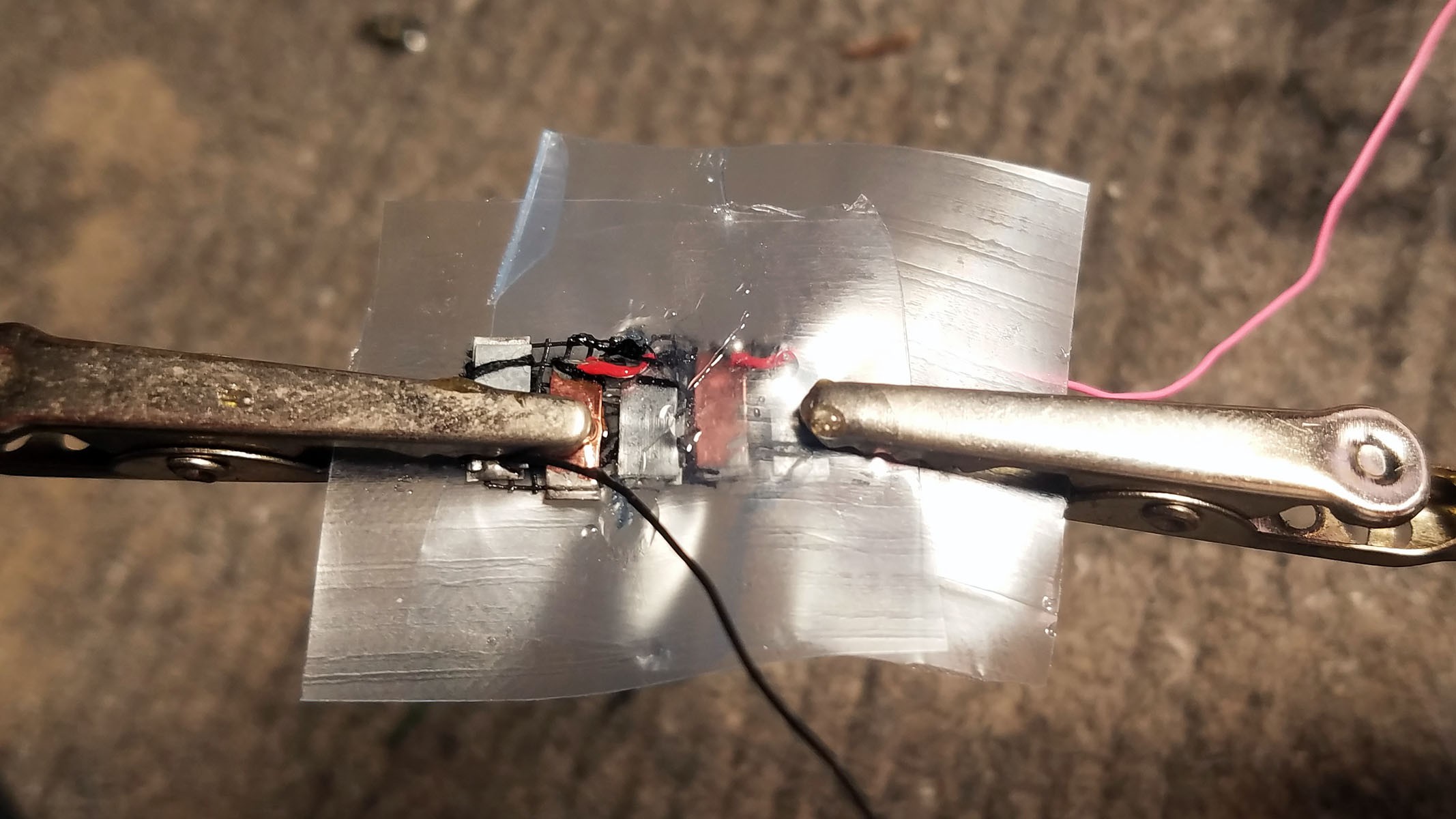
    The three galvanic cells are producing an electrical short between cells. In an attempt to ameliorate this, I have created plastic flap ion barriers between the cells. I cut out squares from a heavy duty plastic zip-lock bag and cut slits that are just a little smaller than the widths of the anode and cathode metal strips. I then pulled the cells through these holes until the plastic flaps separate the three galvanic cells. Once the flaps were properly arranged, I sealed them with epoxy. This isn't working quite as well as I had hoped, but it shows promise (see project log on testing cells).

    Plastic flaps are arranged between cells.

    The slits in the plastic flaps are sealed with epoxy. Once the epoxy is mostly set but still a little pliable the flaps are folded down so the cell bank can fit inside the smart pill enclosure.

  • 2
    Constructing a Magnesium-Copper Galvanic Cell

     Raw materials:  copper sheet cut into strips, magnesium ribbon, silver solder, plastic mesh backing, black thread.

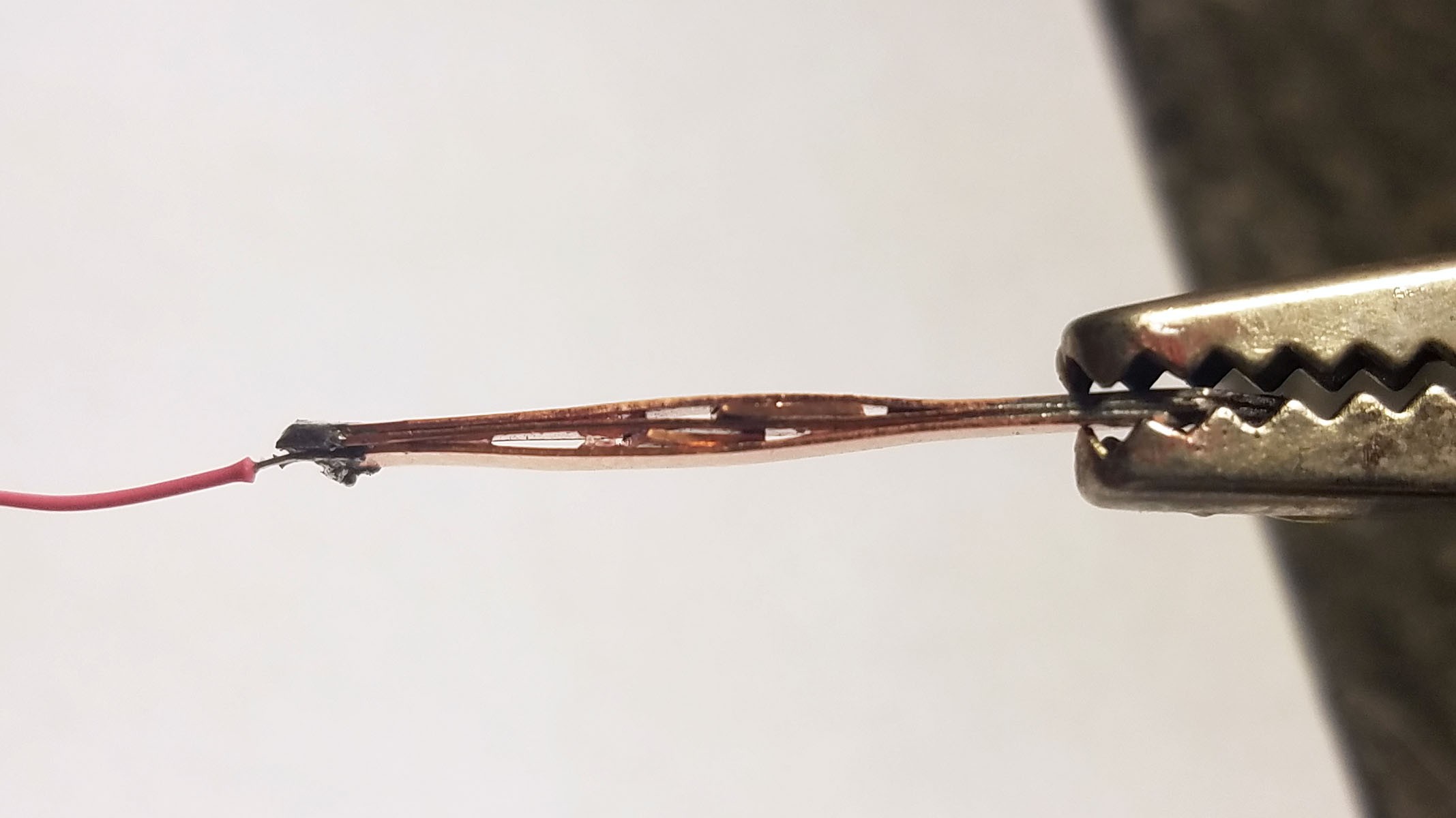
    Three magnesium strips and three copper strips 28mm*3.5mm are cut with corners trimmed to allow for fit into plastic pill enclosure.

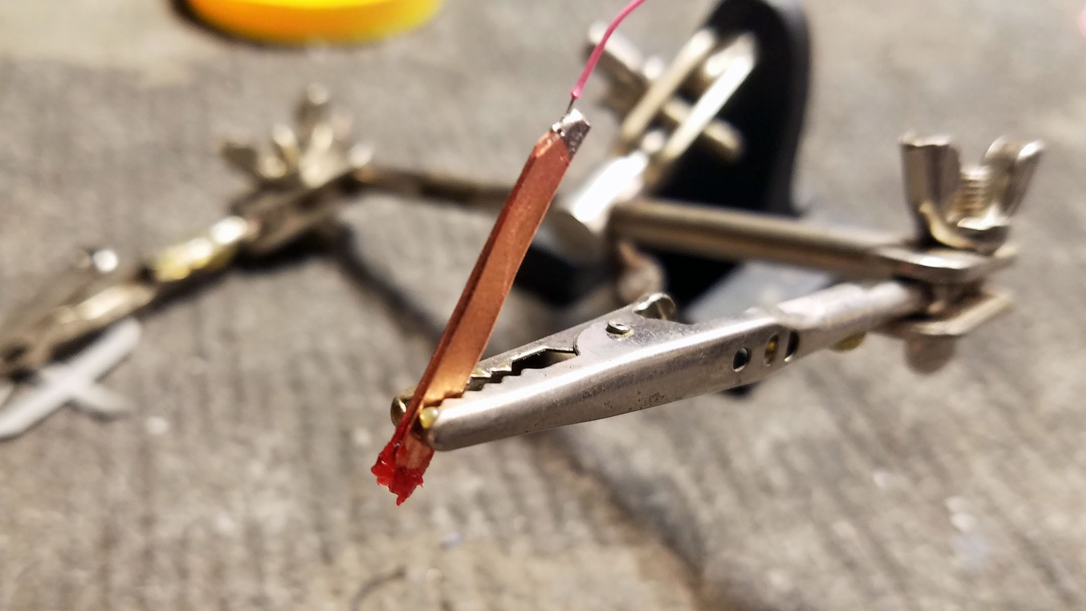
    Three copper strips are soldered together at the ends with a wire lead. 

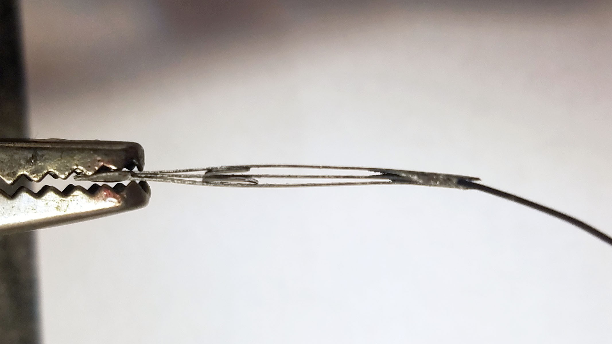
    The strips are then wedged apart with small bits of sheet copper to ensure maximum exposure to electrolyte.

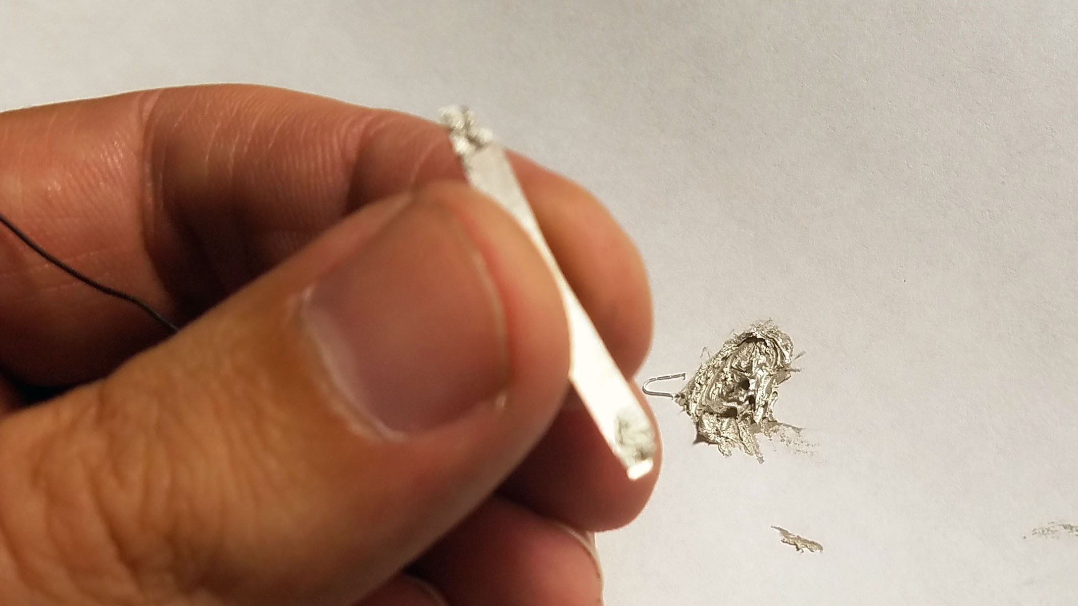
    Three magnesium strips are glued together at the tips with silver conductive epoxy. Magnesium cannot be soldered. A lead wire is also epoxied onto one end.

    The magnesium strips are wedged apart with pieces of magnesium ribbon to maximize exposure to electrolyte. 

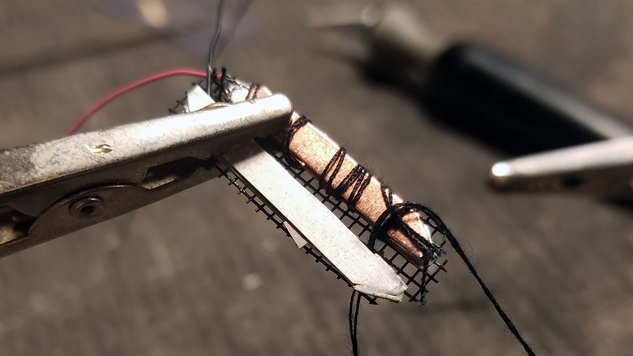
    The stacks of Magnesium and Copper strips are sown onto a plastic mesh backing to ensure proper parallel spacing.

    Completed Magnesium-Copper galvanic cell.

View all instructions

Enjoy this project?

Share

Discussions

Curt White wrote 07/17/2018 at 15:34 point

I'd really like to get this working with Bluetooth. Once of my prime objectives is to make medical device research conducted in expensive university labs more open and less expensive. The MIT team that did a similar experiment used a transmitter in the 900MHz range. I tried placing an activity tracker in a box lined with one inch thick gel/water ice packs (room temperature) and I was able to detect BLE GAP broadcasts + connect over BLE GATT. Granted 1" of mater/silicate gel isn't the same as the abdomen wall. Do you have any suggestions for making this work better using Bluetooth?

  Are you sure? yes | no

Mark Jeronimus wrote 07/13/2018 at 09:58 point

Isn't the galvanic cell going to degrade quickly, because of the "short circuit" between the Cu of one cell and the Zn of the next cell?

  Are you sure? yes | no

Dylan Brophy wrote 07/13/2018 at 16:35 point

Good point. I also don't want copper and zinc dissolved in my stomach acid. This is a problem I've thought about before; how could we make the cells not degrade?

  Are you sure? yes | no

Martin wrote 07/17/2018 at 13:15 point

No, you can not. Any galvanic cell (battery) degrades in use.

But it's not that bad: zinc is an essential mineral anyway. You need about 10mg/day and should not have more than 25mg/day. More than 200mg can lead to problems like vomiting and diarrhea. Overdoses of zinc can lead to insufficient absorption of copper. I think this will be compensated here :-)

  Are you sure? yes | no

Dylan Brophy wrote 07/17/2018 at 15:53 point

Oh - thank you for educating me. XD

  Are you sure? yes | no

A. M. Aitken wrote 08/03/2018 at 23:24 point

The copper will not dissolve.  The cell will also polarise, which will reduce the voltage.

  Are you sure? yes | no

Curt White wrote 07/14/2018 at 04:40 point

Yup, the cells have to be isolated. The amount of zinc and copper ingested is completely harmless, but to each their own.

  Are you sure? yes | no

Martin wrote 06/21/2018 at 12:52 point

This not "powered by stomach acid" It's powered by the oxidation of the Mg Electrode.

I vaguely remember a similar device from a drawing >30yr. ago. It was a simple design without any digital electronics, transmitting probably temperature and acidity. The supply electrodes were supposed to serve as sensors for the pH. I don't know how widespread such a sensor pill was at that time or if it was more or less a concept.

  Are you sure? yes | no

Curt White wrote 06/21/2018 at 13:30 point

Don't worry, I'll be adding a section devoted to relevant electrochemistry when I have a chance, just got back from vacation and I have to catch up on a lot of stuff. 

  Are you sure? yes | no

Martin wrote 07/17/2018 at 13:05 point

The electrochemistry is quite clear. My comment is about the misleading concept of "powered by lemon juice", powered by water" or "powered by stomach acid". All this is not true. It is just battery powered, with a crude, open battery. You already noticed, you can not successfully connect the cells in series, the ions do not know, that they should travel to the left and not to the right metal strip (where the supposed series connection is nothing more than a short circuit).

If you solder (copper) wires to your electrodes, do not forget that solder is also a different metal, which has it's own electrochemical potential and can lead to electrolytic corrosion if you do not insulate the connections very good. And do not use leaded solder when you really think about ingesting this contraption - for normal projects I avoid leadfree solder, but in this case...

If you really want to power this by a battery using stomach acid as an electrolyte, you need a single cell concept. There are step-up converters for power harvesting, which run from less than 1V, I think you have to look at Linear Technology or Maxim.

But I think it makes more sense to use a tiny CR927 or CR1025 lithium button cell (or 2 or 3 Zn/MnO2 watch cells).

I also would not expect Bluetooth to be available of any connection through the body. The frequency of 2,4GHz is quite good absorbed in watery tissue (meat). There is a reason that this frequency was selected for microwave ovens. I know of experiments with an subsea WLAN link (special, extremely expensive equipment): The range in salt water was about 15cm (6").

I think you should reduce the carrier frequency by about 4-5 orders of magnitude and use a magnetic (loop/ferrite) antenna in the VLF or LF range.

  Are you sure? yes | no

esben rossel wrote 06/19/2018 at 04:17 point

This is a really fun, cool and mad scientisty project (especially the part where you swallow the pill yourself).

I only quickly read through the paper, and understand why you want to try with an Mg-anode, but the immediate thoughts that come to mind why Zn is better is that your element is reliant on these reactions (in acidic pH):

(i) Mg → Mg²⁺  +  2e⁻

(ii) 2H⁺ + 2e⁻ → H₂

Reaction (i) obviously takes place at the anode, and reaction (ii) takes places at the Cu-cathode, or rather, it's supposed to. Copper, and the other noble metals, are excellent catalysts for this second reaction, but if your circuit is not "digesting" (haha) enough current, reaction (ii) can just as easily  take place at the anode, bypassing your circuit.

I see you plan to use the element to charge a capacitor-bank, so this might not be an issue. Like I said, these are just immediate thoughts. If it goes well, Mg could certainly a good choice, not only do you get a larger difference in reduction potential, but you also get more Mg-atoms for the same mass of the anode (but with the densities of the two metal as they are, this benefit could cancel out)

In either case I'm very much looking forward to seeing your results

  Are you sure? yes | no

Curt White wrote 06/19/2018 at 05:28 point

I hope I run into the problem of excess available current! You are right though, there will end up needing to be a balance. In my experience with this hacked device, current consumption can't be reduced below 2mA with the MCU fully on which is way more than the galvanic cell can produce. I'm going to have to put it in low power sleep most of the time and figure out how often it needs to be woken up. I'm definitely going to test out both Zn and Mg with Cu on gastric fluid. 

  Are you sure? yes | no

Ben Pottinger wrote 03/18/2019 at 20:53 point

I'm curious what your hoping to diagnose with the device?  Most swallowable medical devices are used to image the small intestine (because you can't get a scope into the small intestine like you can the stomach and the large intestine).  But those devices run a camera, a LED and a radio during their entire trip.  They are also prescribed as a procedure by a physician and not something people would just need to swallow to get a bit more health tracker information.

You mention that people swallow all kinds of things and are "fine".  They also swallow plenty of things and die, horribly, from the stuff they swallowed.  esophageal damage and liver damage are often knock on issues from many items being swallowed.  Trust me, as someone with very serious gastro illnesses don't take swallowing a self made hacked together "pill" lightly. 

  Are you sure? yes | no

Curt White wrote 06/22/2018 at 01:04 point

I'm leaning towards Zn now. You were totally right, Mg(s) + 2HCl(aq) → MgCl₂(aq) + H₂(g) is way more annoying than I thought it would be. Building these little galvanic cells is really tedious and it doesn't take long for the Mg parts to dissolve if they are left to their own devices. That actually wasn't what made me switch to Zn for the time being; Mg can't be soldered and the my conductive epoxy is not doing the trick. 

  Are you sure? yes | no

Curt White wrote 06/17/2018 at 13:16 point

I just started documenting this project today. I was doing the background section first. I've barely begun describing what I'm actually doing. The boost converter with a 1.8v lower range is from an illustration I haven't had a chance to reference, I don't actually use that one. You'll notice redundant nRF5x modules in that illustration as well. These are just for discussion. You may want to check back in a couple days. I think you would find the Nature Biomedical Engineering article ("Prolonged Energy Harvesting For Ingestible Devices") this project is based on really interesting, it goes over some of the subjects you mention in a lot more detail than I have. It is in the "files" section of the project. 

  Are you sure? yes | no

K.C. Lee wrote 06/17/2018 at 12:31 point

>Right this moment, your body contains and is producing a strong acid: stomach acid. 

FYI: It is not just acid in the digestive system of a healthy person. 

http://gastrodigestivesystem.com/digestion/digestion-ph

>In the mouth, the pH is in neutral (or close to neutral),
>In the stomach, the pH is acidic at around two.
>In the small intestine, the pH is basic at around 8
>Finally, it reaches seven as it reaches the end (anus).

---------------------------------------------------------

>G: Strip of Zinc (Zn).
>H: Strip of Copper (Cu).
>I: Small 1.8-5v to 3v DC-DC boost converter.

That's not going to cover the battery voltage.

https://en.wikipedia.org/wiki/Lemon_battery

>This effect ultimately limited the voltage of the cells to 1.0 V near room temperature at the highest levels of acidity.

  Are you sure? yes | no

Similar Projects

Does this project spark your interest?

Become a member to follow this project and never miss any updates