 Curt White
-
1Constructing the Zinc-Copper Galvanic Cells
![]()
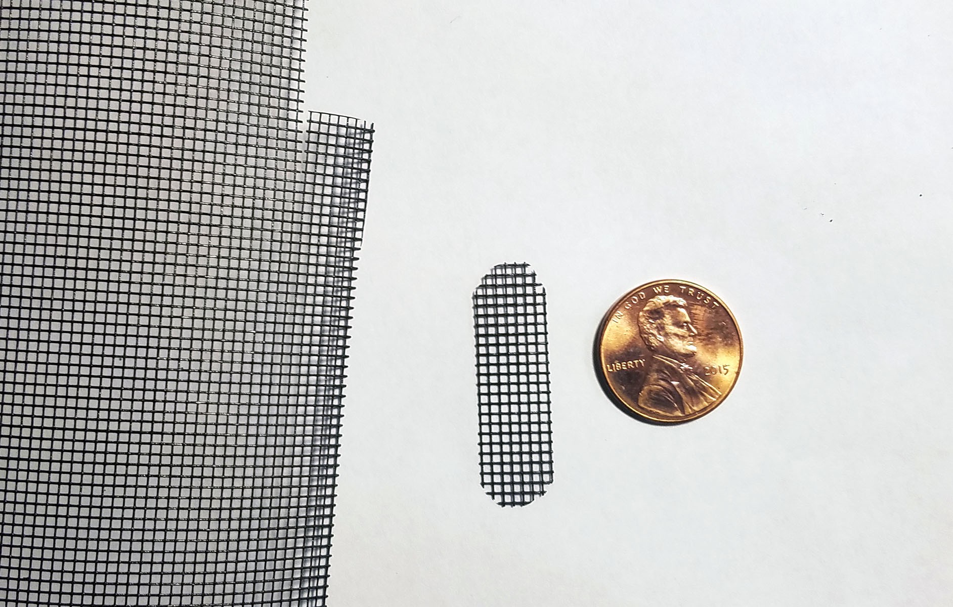
The activity tracker PCB is used to trace and cut out a piece of plastic mesh so that it will fit flush in the activity tracker enclosure.
![]()
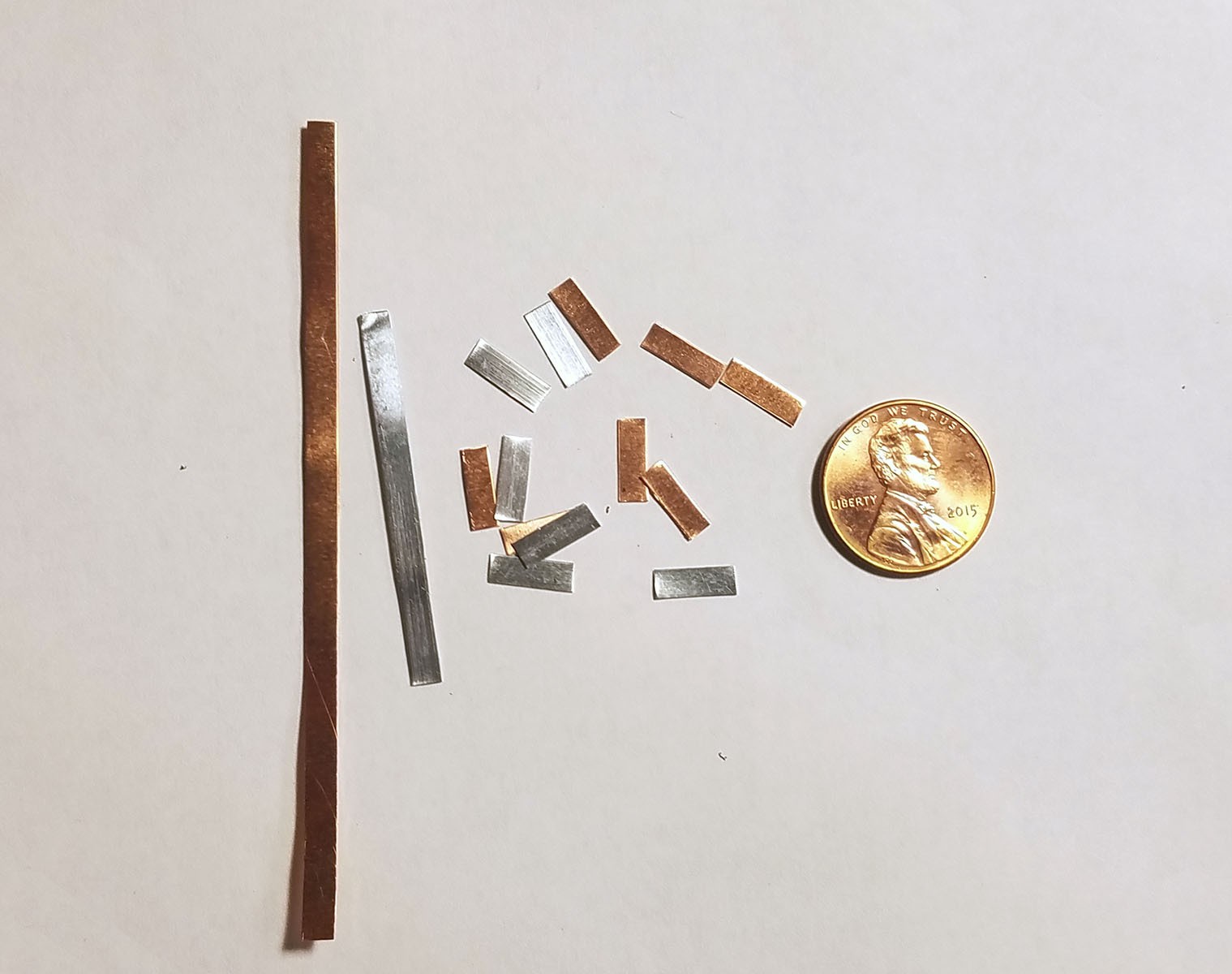
6 strips of copper and 6 strips of zinc are cut 3mm wide and 9mm long (the width of the activity tracker PCB). The copper and zinc are about 0.25mm thick (I purchase 30 gauge sheets).
![]()
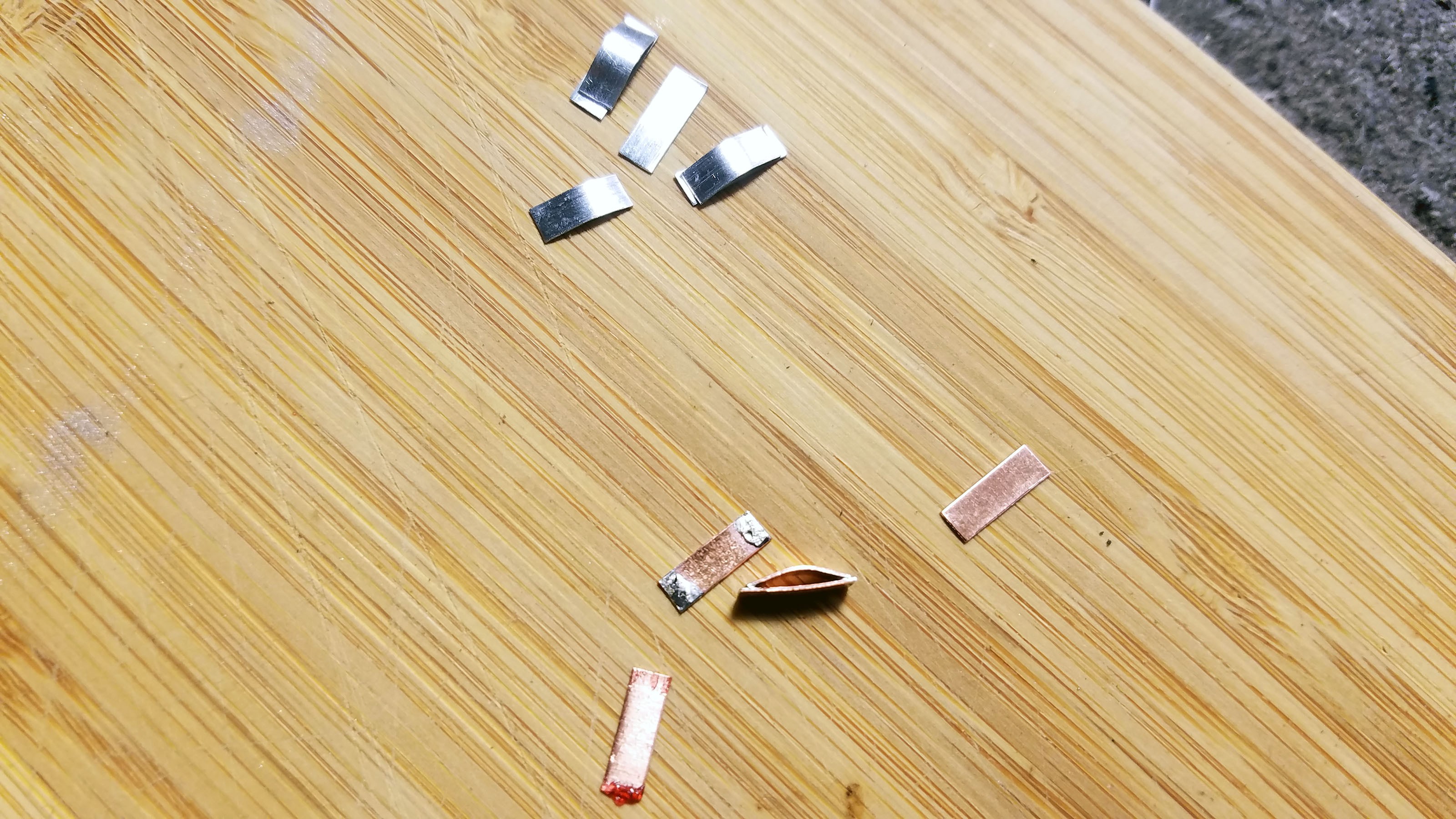
Half of the strips are bent and then soldered to the other half (Cu to Cu etc.) so that the bottom strip is flat and the top strip forms an arch with about 1mm of clearance underneath. These two strip 'sandwiches' will have more mass and greater surface area which will increase the current produced by the galvanic cells.
![]()
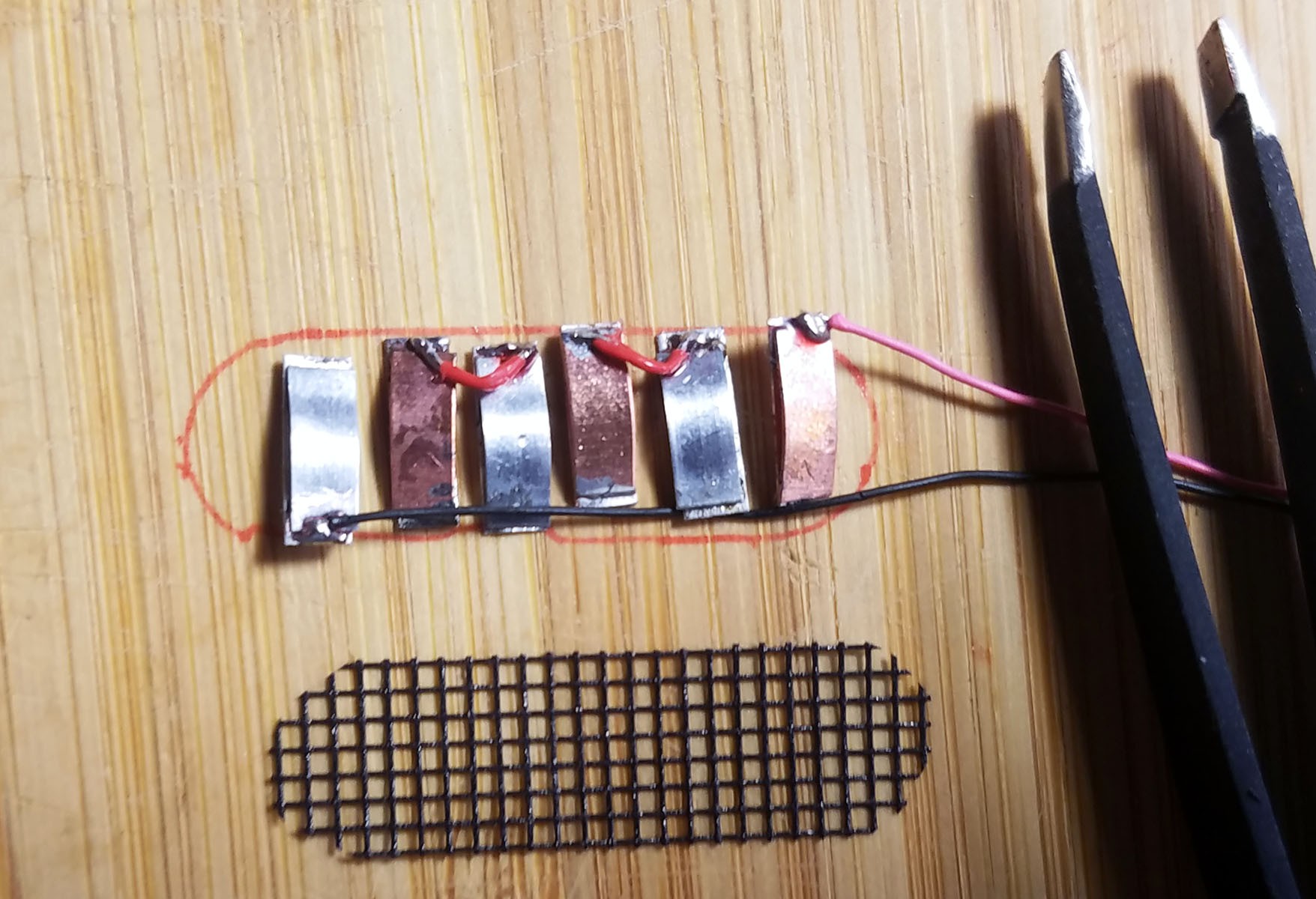
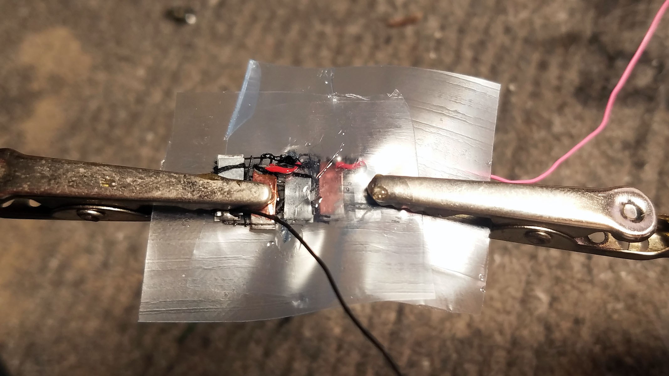
The soldered strip pairs are arranged in alternating order according to metal type. The ground lead for the cells is soldered to the end zinc strip and the positive lead is soldered to the end copper strip. Each of the remaining copper strips is soldered to one of the remaining zinc strip to complete a series of three galvanic cell pairs.
![]()
The metal strips are sewn down to the plastic mesh so that they are evenly spaced apart when the entirety is placed inside the activity tracker plastic enclosure.
![]() The completed array of galvanic cells is placed inside the enclosure to make sure everything fits and stays in place.
The completed array of galvanic cells is placed inside the enclosure to make sure everything fits and stays in place.POST TESTING ADDITIONAL STEPS
The three galvanic cells are producing an electrical short between cells. In an attempt to ameliorate this, I have created plastic flap ion barriers between the cells. I cut out squares from a heavy duty plastic zip-lock bag and cut slits that are just a little smaller than the widths of the anode and cathode metal strips. I then pulled the cells through these holes until the plastic flaps separate the three galvanic cells. Once the flaps were properly arranged, I sealed them with epoxy. This isn't working quite as well as I had hoped, but it shows promise (see project log on testing cells).
![]()
![]()
Plastic flaps are arranged between cells.
![]()
The slits in the plastic flaps are sealed with epoxy. Once the epoxy is mostly set but still a little pliable the flaps are folded down so the cell bank can fit inside the smart pill enclosure.
-
2Constructing a Magnesium-Copper Galvanic Cell
![]()
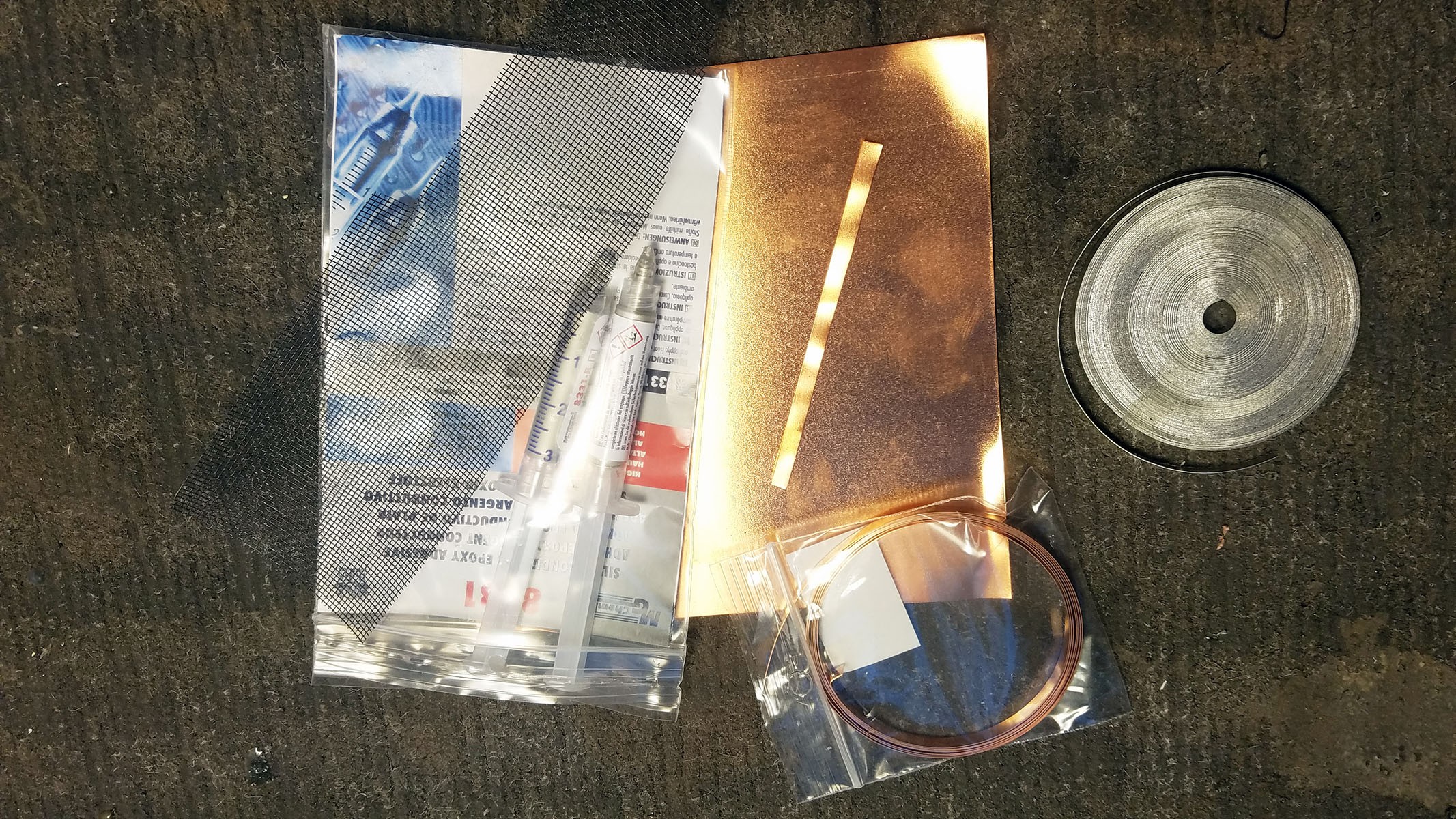
Raw materials: copper sheet cut into strips, magnesium ribbon, silver solder, plastic mesh backing, black thread.
![]()
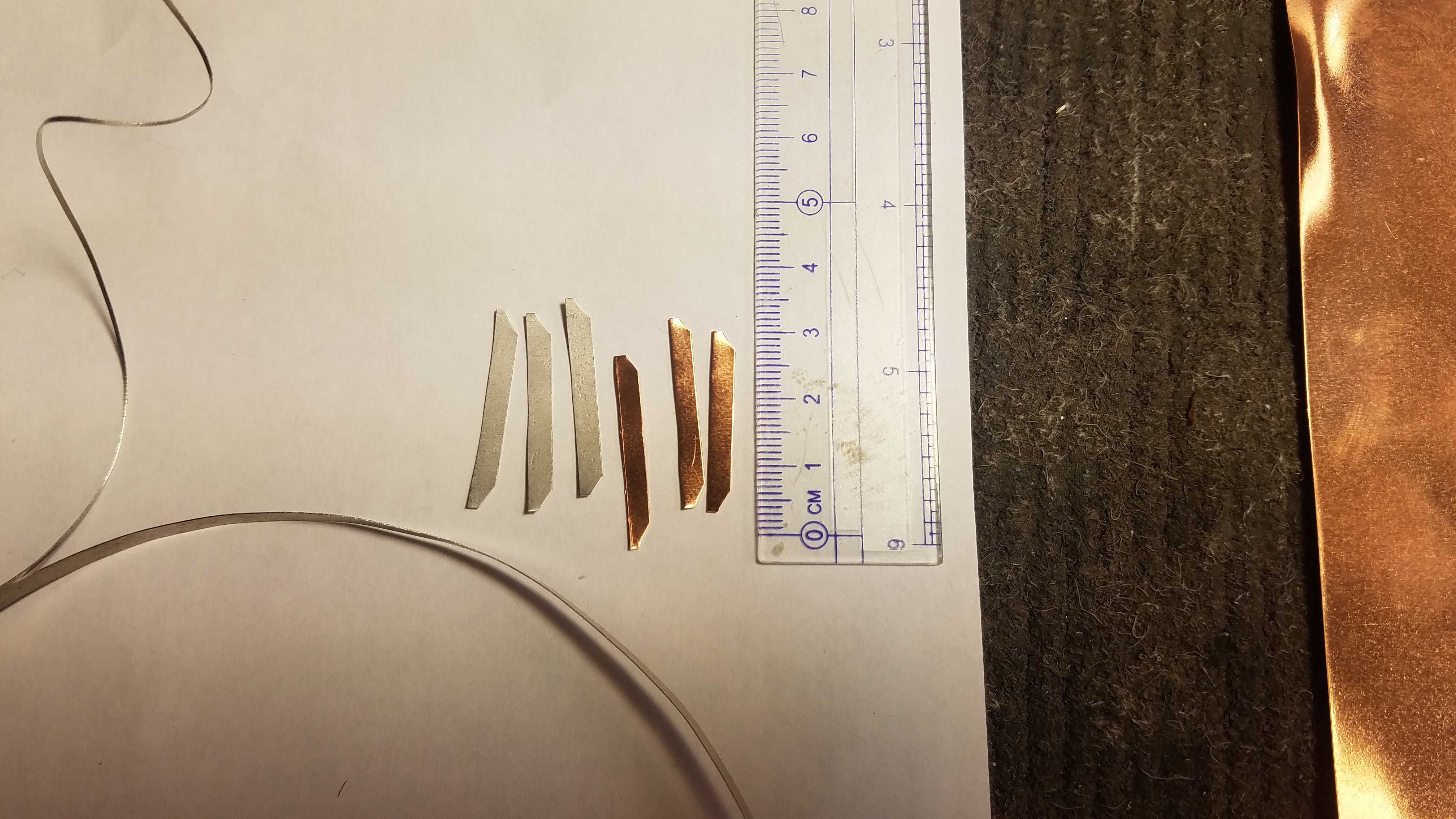
Three magnesium strips and three copper strips 28mm*3.5mm are cut with corners trimmed to allow for fit into plastic pill enclosure.
![]()
Three copper strips are soldered together at the ends with a wire lead.
![]()
The strips are then wedged apart with small bits of sheet copper to ensure maximum exposure to electrolyte.
![]()
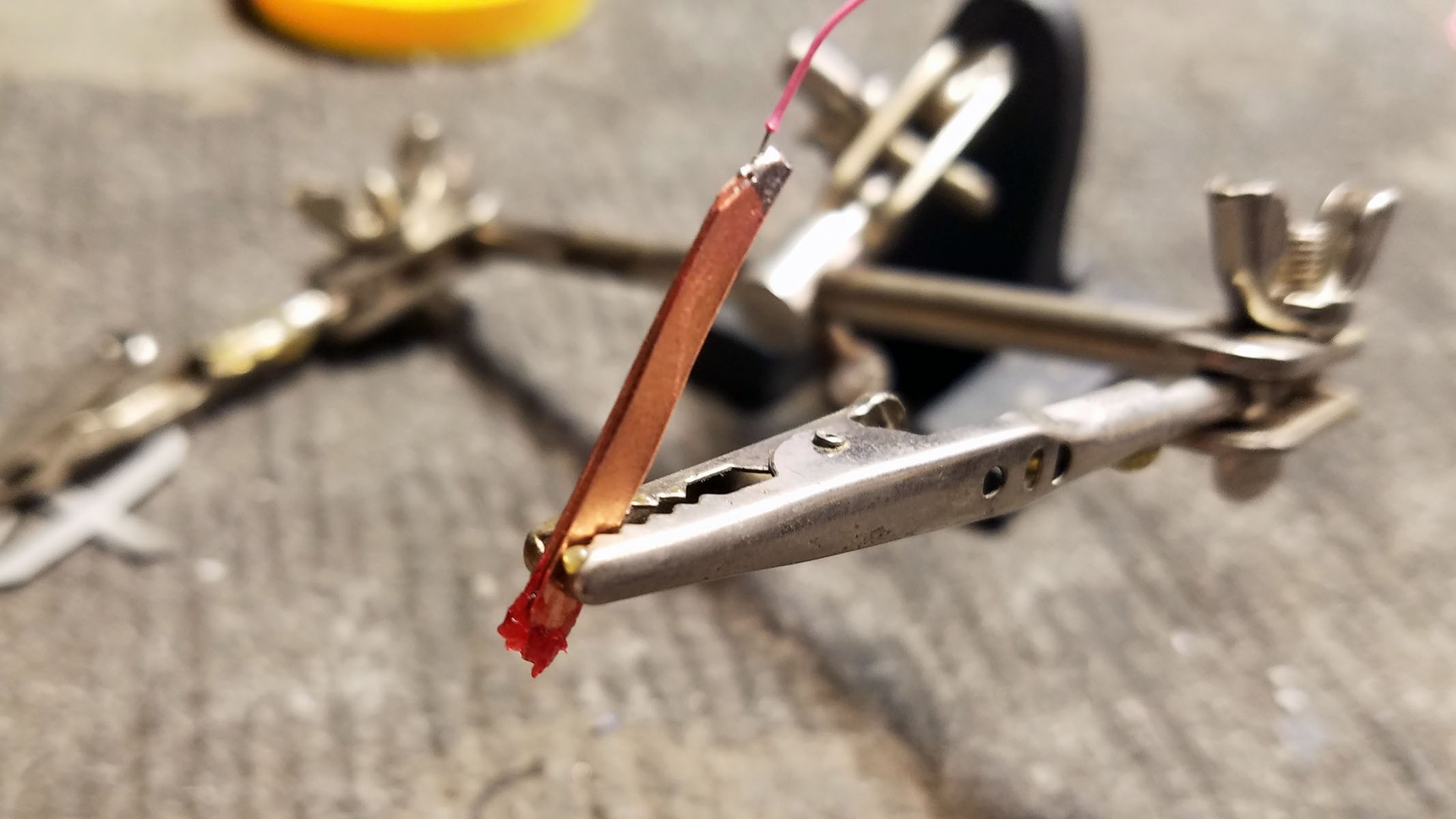
Three magnesium strips are glued together at the tips with silver conductive epoxy. Magnesium cannot be soldered. A lead wire is also epoxied onto one end.
![]()
The magnesium strips are wedged apart with pieces of magnesium ribbon to maximize exposure to electrolyte.
![]()
The stacks of Magnesium and Copper strips are sown onto a plastic mesh backing to ensure proper parallel spacing.
![]()
Completed Magnesium-Copper galvanic cell.
Stomach Acid Powered Smart Pill
Zn-Cu stomach acid based bio-galvanic cell powers a hacked activity tracker small enough to swallow and reconfigured as a 'smart pill'.
 The completed array of galvanic cells is placed inside the enclosure to make sure everything fits and stays in place.
Discussions
Become a Hackaday.io Member
Create an account to leave a comment. Already have an account? Log In.